

Page 1

EX
MicroVision
MICROPROCESSOR – BASED
WATER TREATMENT
CONTROLLER
Installation Operation Manual
72-900-06 Rev. F
Page 1 of 38
Page 2

Table of Contents
1. GENERAL WARNINGS ............................................................................................................................... 4
2. MicroVision
3. INSTALLATION ............................................................................................................................................ 6
3.1 Location ...................................................................................................................................................... 6
3.2 Mounting Hardware ............................................................................................................................... 6
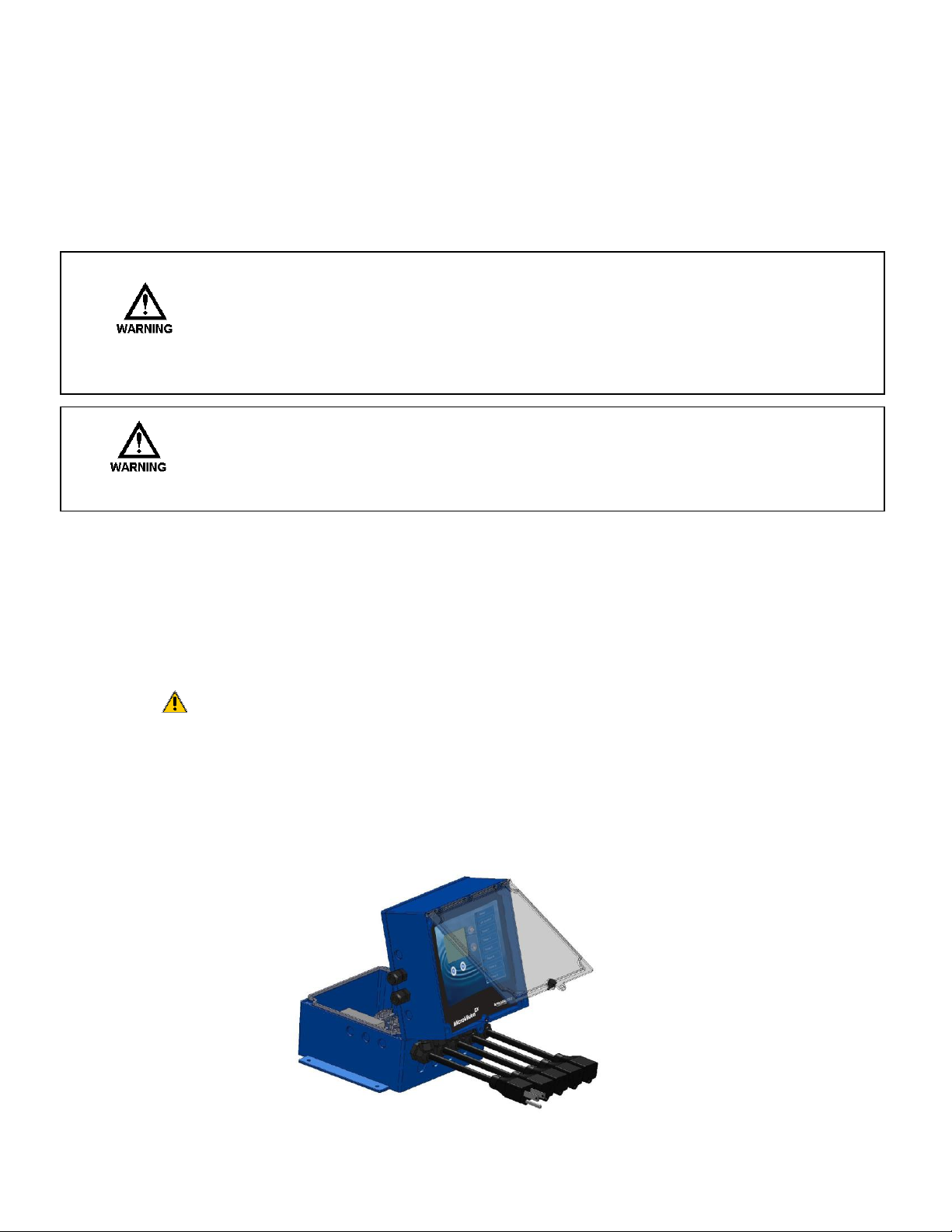
3.3 Opening the Enclosure ......................................................................................................................... 6
3.4 Sensor Installation ................................................................................................................................. 7
3.5 TYPICAL INSTALLATION ...................................................................................................................... 7
3.6 IMPORTANT SYMBOL INFORMATION .............................................................................................. 8
3.7 ELECTRICAL WIRING ............................................................................................................................ 8
3.8 Flow Switch Input ................................................................................................................................ 12
3.9 Sensor (probe) Connection Input .................................................................................................. 12
3.10 Water Meter Input ........................................................................................................................... 12
3.11 Drum Level Input ............................................................................................................................. 12
3.12 4-20mA Output ................................................................................................................................. 12
3.13 4-20mA Input .................................................................................................................................... 12
3.13.1 Fluorometer – Trace Chemical ............................................................................................ 13
3.13.2 Calibrating PTSA Probe .......................................................................................................... 14
3.14 Alarm Dry Contact Relay ............................................................................................................... 14
3.15 Keypad Operation ............................................................................................................................ 15
3.16 Communications (Optional) ......................................................................................................... 15
4. CONTROLLER PROGRAMMING ............................................................................................................. 16
4.1 Menu Map ................................................................................................................................................ 16
4.2 Menu Navigation ................................................................................................................................... 16
4.3 Home screen .......................................................................................................................................... 16
4.4 Main Menu ............................................................................................................................................... 17
4.5 Relay HOA ............................................................................................................................................... 17
4.6 Configure ................................................................................................................................................. 17
4.6.1 Date/Time ....................................................................................................................................... 17
4.6.2 Digital Inputs ................................................................................................................................. 18
4.6.3 4-20mA Out and 4-20mA In .................................................................................................... 18
4.6.4 Gal/Lit ............................................................................................................................................... 18
4.6.5 Meter Totals .................................................................................................................................... 18
4.6.6 Languages Menu ........................................................................................................................... 18
4.6.7 Display Settings ............................................................................................................................ 19
4.6.8 Password Setting .......................................................................................................................... 19
4.6.9 Software Version .......................................................................................................................... 20
4.6.10 Factory Reset Function ........................................................................................................... 20
4.7 Settings .................................................................................................................................................... 20
4.7.1 Conductivity ................................................................................................................................... 20
4.7.2 pH and ORP .................................................................................................................................... 22
4.7.3 4-20mA Outputs (Optional Accessory) ................................................................................ 24
4.7.4 4-20mA Inputs (Optional Accessory) ................................................................................... 24
4.8 Timers - Modes ..................................................................................................................................... 24
4.8.1 Timers – Pulse Timer .................................................................................................................. 25
4.8.2 Timers – Percent Timer ............................................................................................................. 25
4.8.3 Timers - 28 day (Biocide Timer) ............................................................................................ 25
4.8.4 Timers – % Post Bleed ............................................................................................................... 26
4.8.5 Timers – Limit Timer (Bleed and Feed) ............................................................................... 26
4.8.6 Timers – Alarm .............................................................................................................................. 26
72-900-06 Rev. F
Page 2 of 38
EX
FEATURES .......................................................................................................................... 4
Page 3

4.8.7 Timers – Set Point Control Mode ........................................................................................... 26
4.8.8 Timers – Disabled (Default) ..................................................................................................... 27
4.8.9 Timers – Bio Tracking (In All Timer Modes) ...................................................................... 27
4.9 Communications ................................................................................................................................... 27
4.10 USB ........................................................................................................................................................ 27
4.10.1 USB Graphing Tool .................................................................................................................. 28
4.10.2 USB Data log Timer and Tamper Codes: ........................................................................ 28
4.11 Ethernet (Optional) ......................................................................................................................... 29
4.11.1 Programming your controller PulsaLink........................................................................... 29
4.11.2 Setting Up Your Controller on PulsaLink ......................................................................... 29
5. FACTORY DEFAULTS ............................................................................................................................... 30
6. TROUBLESHOOTING GUIDE ................................................................................................................. 32
7. MAINTENANCE ........................................................................................................................................... 33
7.1 Conductivity Sensor removal and cleaning ................................................................................ 33
To remove the conductivity sensor from its tee for cleaning: .................................................... 33
To clean conductivity sensor: .................................................................................................................. 33
7.2 pH sensor Information ....................................................................................................................... 33
7.2.1 Preparation ..................................................................................................................................... 33
7.2.2 Sensor Storage ............................................................................................................................. 34
7.2.3 Sensor Cleaning ............................................................................................................................ 34
7.3 ORP Sensor Information .................................................................................................................... 34
7.3.1 ORP Maintenance and Troubleshooting ............................................................................... 34
7.3.2 Testing ORP Sensor ..................................................................................................................... 34
7.3.3 Flow Sensor .................................................................................................................................... 35
8. SPECIFICATIONS ...................................................................................................................................... 35
9. FORSEABLE MISUSE ............................................................................................................................... 36
10. MOUNTING HOLE PATTERN (Footprint) ........................................................................................... 37
72-900-06 Rev. F
Page 3 of 38
Page 4

Introduction
RELAY STATUS
LED COLOR
ON (FORCED ON FOR 5 MIN.)
AMBER
OFF
RED
AUTOMATIC ‘ON’
GREEN
AUTOMATIC ‘OFF’
OFF
The MicroVisionEX microprocessor based cooling tower controller has been designed to
monitor and control Total Dissolved Solids (TDS) in terms of electrical conductivity
measured in micro Siemens per centimeter (uS/cm). Some models also include pH, and
ORP control. A set point of the desired value to control is entered into the controller
through the front panel. As this limit is exceeded, a valve, pump or other control device
is activated via an onboard control relay to adjust the reading being measured.
1. GENERAL WARNINGS
Symbol hereinafter and upon the unit means WARNING!
If the equipment is used in a manner not specified by the manufacture, the overall
safety may be impaired.
The plug is considered mains power. Disconnection means should be readily
identifiable and easily accessible to the operator after install
Adequately rated and APPROVED/CERTIFIED power supply cord and plug (supplied
by Pulsafeeder), or cable gland suitable for the applicable country is to be attached
and replaced by manufacturer’s authorized qualified person or as per applicable local
and national regulations
Controller is for indoor use only and not suitable for wet location. Controller housing
is IP65 compliant and may be configured as such.
Verify the mains supply ratings (e.g. Volts, Amps, and Hz) where the controller is to
be powered from and ratings of the accessories as well as ratings of the controller’s
receptacles/outlets before powering up.
2. MicroVisionEX FEATURES
Toroidal Probe
MicroVisionEX uses a toroidal probe for conductivity measurement. The
measurement is made by passing an AC current through a toroidal drive coil,
which induces a current in the electrolyte solution. This induced current in turn,
induces a current in a second toroidal coil, called the pick-up toroid. The amount
of current induced in the pick-up toroid is proportional to the solution conductivity.
Output Relays
The control of the HANDS – OFF – AUTO (HOA) output relays can be controlled using the
HOA menu.
72-900-06 Rev. F
Page 4 of 38
Page 5

Drum Levels
Three (3) onboard dry contact inputs serve as Drum Level inputs. When a low level is
detected the unit will go into an alarm state and the low drum’s identity will be displayed
on the screen. The user can program the alarm to deactivate a timer if desired. Drum
level #1 is assigned to timer #1, drum level #2 is assigned to timer #2 and drum level
#3 is assigned to timer #3.
Flow Switch
MicroVisionEX has a dry contact flow switch input that will de-activate all of the control
output relays upon a no-flow indication. An alarm condition will be indicated and “Flow
Switch Alarm” will be displayed. This input is active closed:
Open = no flow; closed = flow.
If a flow switch input or other alarm condition exists, the LED’s on the front
panel will flash until the alarm condition is cleared.
4-20mA Outputs and Inputs
Optional 4-20mA inputs or outputs can be installed to increase the capabilities of the
MicroVisionEX. Connect 4-20mA equipment to the + and – terminals as shown on page 9.
Water Meter
MicroVisionEX has a dedicated water meter input that is capable of reading a dry contact
or Hall effect type water meter. Through programming this input can be used to signal a
pulse timer as well as totalizing water consumption. Some models offer up to six (6)
water meter inputs.
Alarm Relay
MicroVisionEX has a dedicated dry contact relay that can be used to interface with process
control equipment or visual indicators. This relay is un-powered.
72-900-06 Rev. F
Page 5 of 38
Page 6
3. INSTALLATION
3.1 Location
Select a mounting location convenient to grounded (True Earth) electrical and
plumbing connections. It is recommended that the controller is mounted on a wall or
other vertical surface with adequate lighting at a comfortable level. Installation
should comply with all national, state, and local codes.
Avoid locations where the controller would be subjected to direct
sunlight, extreme cold, heat, or humidity {less than 36°F (2.2°C) or
greater than 122°F (50°C), or greater than 95% RH non-condensing,
direct sunlight, vibration, vapors, liquid spills, or EMI (electromagnetic
interference; e.g., strong radio transmission and electric motors.)
Install at less than 2000m above sea level.
SAFETY PROTECTION PROVIDED BY THE EQUIPMENT MAY BE IMPAIRED IF THE
EQUIPMENT IS USED IN A MANNER NOT SPECIFIED BY THE MANUFACTURER.
THIS CONTROLLER IS INTENDED FOR INDOOR USE ONLY AND NOT SUITABLE
FOR WET LOCATION.
3.2 Mounting Hardware
Mount the controller using the four (4) holes provided.
Typically, use a #8 screw or equivalent. The mounting screw should be appropriate
for the location mounting on, i.e., sheet metal screws for mounting onto sheet metal,
wood screws for mounting onto wood or wall studs, and hollow wall drywall anchors
for mounting to drywall. Mount should be designed for 7.5 Kg, 17 lbs.
Mount the unit ergonomically, such that the unit is visible without excessive
bending or lowering of the body, and not too high such that the internals are
not visible with opening the enclosure.
3.3 Opening the Enclosure
Loosen the knob that secures the clear front cover. Then loosen four (4) screws in
the four corners of the front of the controller and carefully swing the top of the case
forward.
72-900-06 Rev. F
Page 6 of 38
Page 7
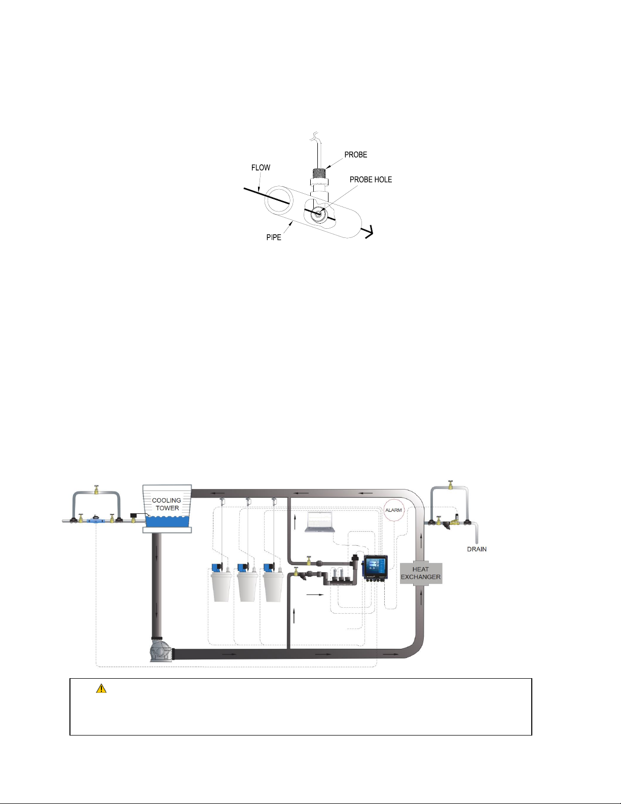
3.4 Sensor Installation
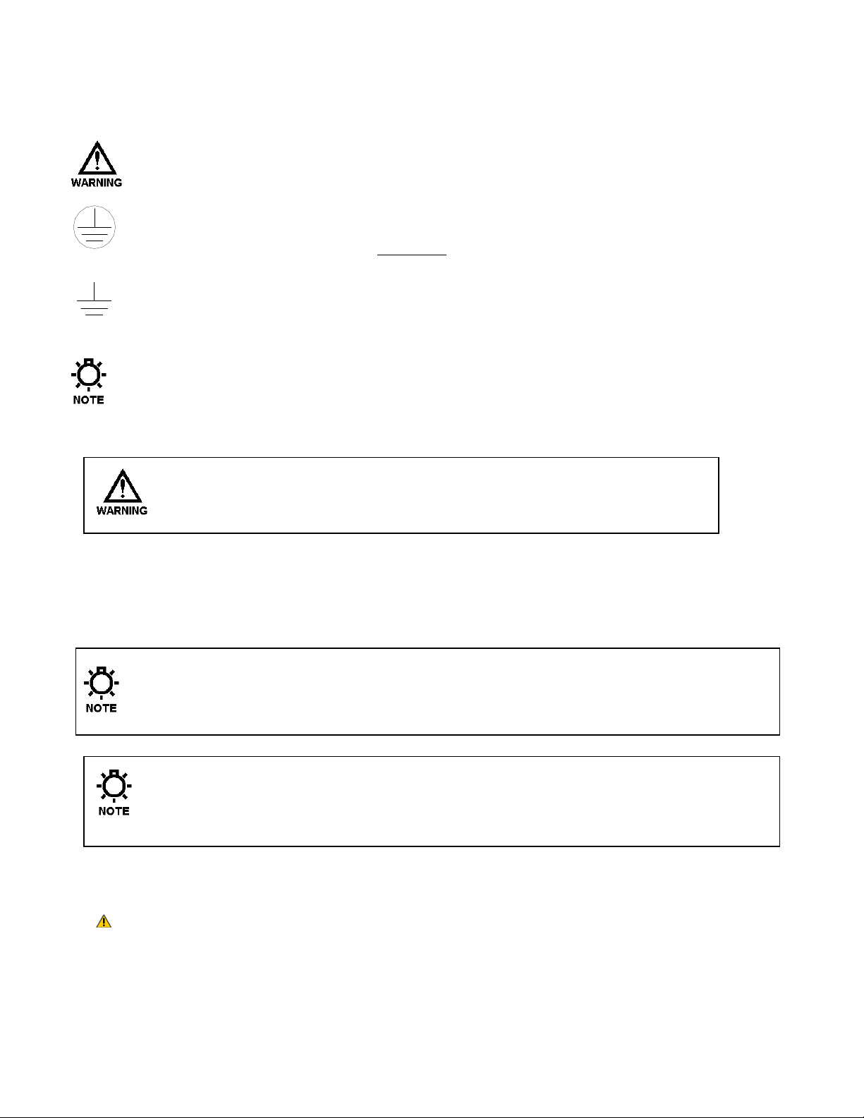
Over pressurization of the plumbing can occur when cooling tower is higher than the
piping and controller system. Ensure all pressures have been accounted for. Verify piping
and sensor allowable temperatures are above maximum temperatures of the system.
Conductivity
The controller is supplied with a temperature compensated toroidal conductivity probe
installed in a tee. The probe should only be installed where adequate flow is going around
and through the hole in the center of the probe in the tee provided.
pH and ORP
When ordered as a pH or ORP model the controller will be supplied with standard pH and
ORP probes. The probes are supplied installed in a tee. The probes should only be installed
where flow between 1 and 5 GPM is going around the probe.
Flow Switch
If the controller is provided with a flow switch, install the flow switch so that flow enters
into the bottom of the flow switch tee, and out the side of the tee. The flow switch must
always be installed in a vertical position so that the sensor wire is coming out of the top,
and the internal (red) flow shuttle is able to rise when there is flow and drop when there is
no flow. The flow switch is activated when 1 GPM (3,8 LPM) is going through it, and is
deactivated when the flow drops below 1 GPM (3,8 LPM).
3.5 TYPICAL INSTALLATION
72-900-06 Rev. F
Page 7 of 38
Page 8
3.6 IMPORTANT SYMBOL INFORMATION
Warning indicates a condition that could cause damage to both the
equipment and the personnel operating it. Pay close attention to any
warning.
Primary Supply Ground must be connected to earth ground for safe
operation of the controller.
Chassis Ground – Connect the equipment’s ground wire here for safe
operation of external devices.
Notes to provide tips and hints
3.7 ELECTRICAL WIRING
CONTROLLER MUST BE WIRED IN ACCORDANCE WITH ALL APPLICABLE
ELECTRICAL CODES, NEC, CSA, EN, OR LOCAL AUTHORITY HAVING
JURISDICTION.
The MicroVisionEX electronic input circuitry is fuse protected on both the hot and
neutral inputs using a replaceable eight amp fuse (see page 9). For additional
protection of this instrument, use of a surge protector is recommended.
The controller should be connected to a dedicated power branch (i.e., its
own wiring, GFCI circuit breaker, etc.). For best results, the ground
should be independent (true earth) not shared.
A switch or circuit-breaker, marked as the unit’s disconnecting device
should be included in the installation. It should be in close proximity to
the unit and be easily reached by the operator.
Pre-wired controllers are supplied with a 3-wire grounded power cord and 3-wire
grounded receptacle cords for all controlled line voltage outputs.
Plug is considered as mains power disconnecting device which shall be readily
identifiable and easily accessible.
72-900-06 Rev. F
Page 8 of 38
Page 9
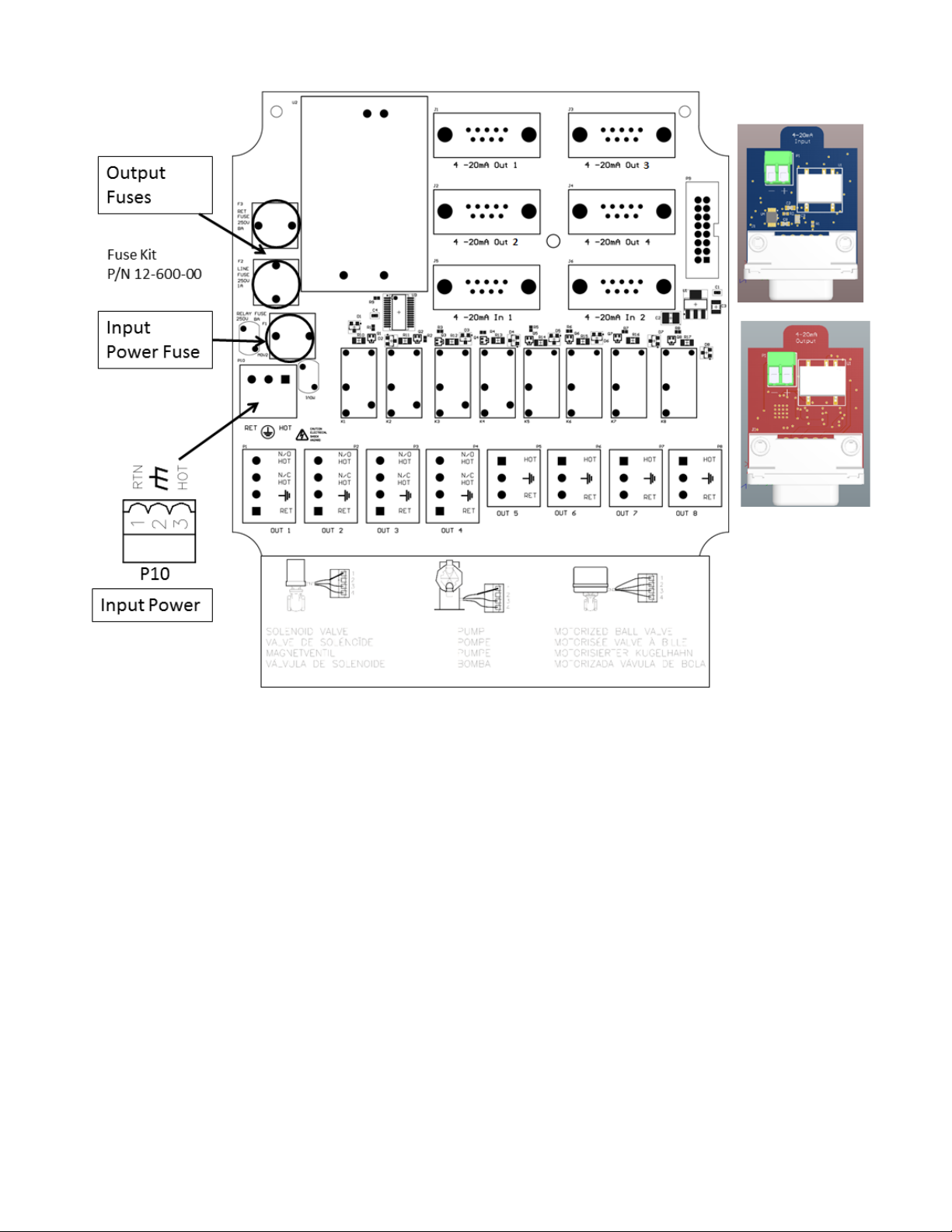
RELAY BOARD CONNECTIONS
Energy Usage and Duty
The unit utilizes a variety of probes and input signals to control valves, pumps,
and numerous other devices. These items are not all used in a continuous
fashion. The typical unit has a complicated duty cycle dependent on application.
For 120V and a max of 8A, a typical duty cycle of 15 minutes on and 45 minutes
off can be used. This results in an energy calculation of
120V * 8A *Power Factor* 25%
The Power Factor is the cosine of the phase angle between the Current and
Voltage of an AC circuit. Typically, 0.8 is a good estimate for US power.
The 25% is the estimate of a typical duty cycle of 15 on and 45 off.
For 240V, the amperage remains constant.
72-900-06 Rev. F
Page 9 of 38
Page 10
Relay Assignments
Relay 1
Relay 2
Relay 3
Relay 4
Relay 5
Relay 6
Relay 7
Relay 8
Dry contact
Model
OUT 1
OUT 2
OUT 3
OUT 4
OUT 5
OUT 6
OUT 7
OUT 8
P4
MVECXXX
Bleed
Timer 1
Timer 2
Timer 3
Alarm
MVEC5XX
Bleed
Timer 1
Timer 2
Timer 3
Timer 4
Alarm
MVECPXX
Bleed
pH
Timer 1
Timer 2
Timer 3
Timer 4
Timer 5
Timer 6
Alarm
MVECOXX
Bleed
ORP
Timer 1
Timer 2
Timer 3
Timer 4
Timer 5
Timer 6
Alarm
MVECPOX
Bleed
pH
ORP
Timer 1
Timer 2
Timer 3
Timer 4
Timer 5
Alarm
MVECPOM
Bleed
pH
ORP
Timer 1
Timer 2
Timer 3
Timer 4
Timer 5
Alarm
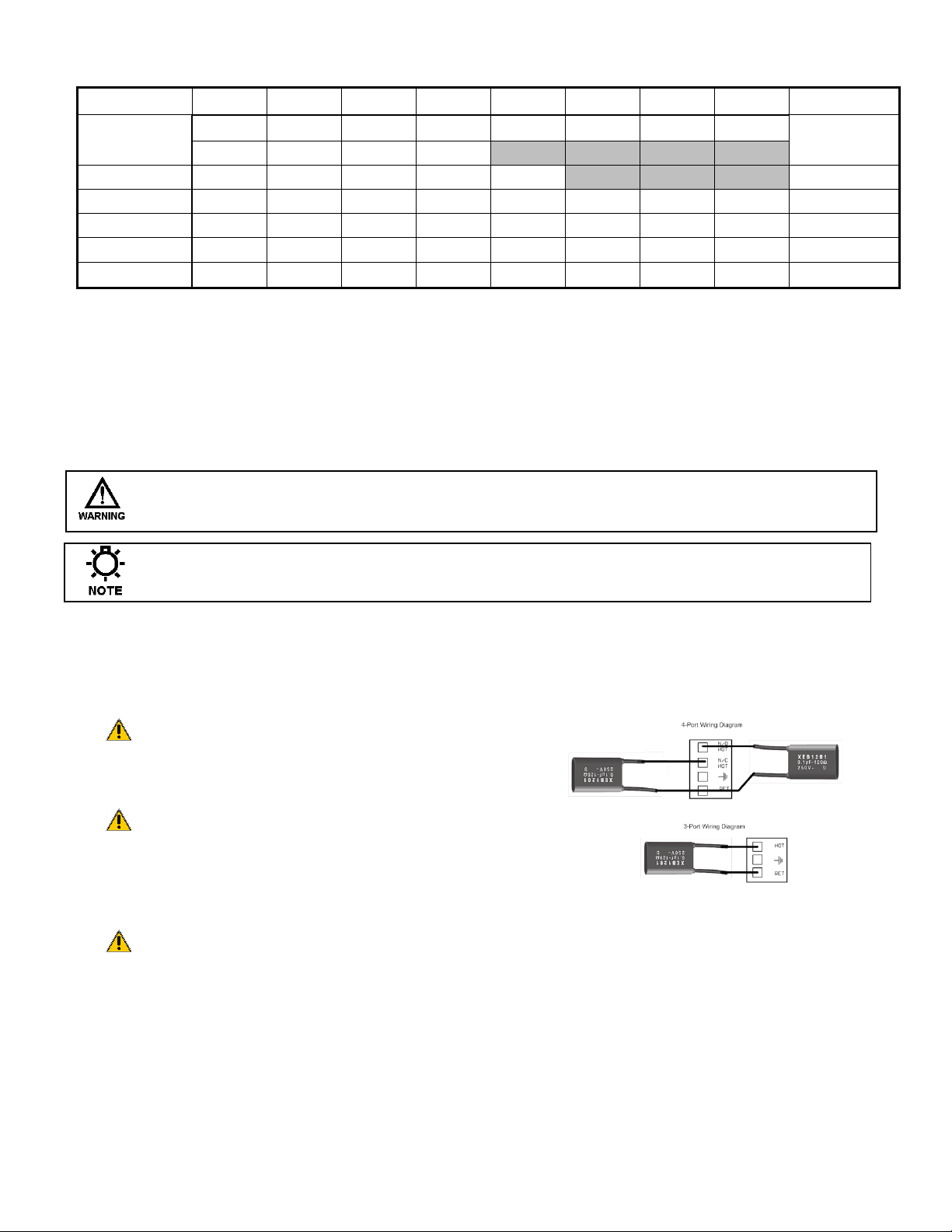
Conduit Models (Wiring High Voltage)
Conduit controllers have openings for conduit connections for hard wiring. Use only 18
AWG (1,2 mm²) stranded wire for conduit power and load connections. Supply (input)
power is connected via P10 located on the relay board. The top part of this terminal block
is removable to allow for easy access to the connector’s three (3) screws. For CE rated
models ensure all ferrites are installed in their specified configuration.
MAKE SURE THAT THE CONTROLLER VOLTAGE MATCHES THE INPUT VOLTAGE
AND OUTPUT VOLTAGES. DO NOT APPLY POWER UNTIL THIS CONDITION IS VERIFIED.
Make sure that all conduit connections are water tight.
The output relay terminal blocks are identified as: OUT 1 through OUT 8 these terminal
blocks can be removed in the same manner as P10. The first four relay outputs have a
N.O. and a N.C. connection, the others are N.O.
Ensure the snubber’s remain on
each of the relay outputs in the
specified wiring configuration.
Unit is to be connected to supply
mains by a qualified personnel in
accordance with local and
national codes e.g. NEC in the U.S. and CEC in Canada.
A suitable power disconnection means is to be provided
e.g. circuit breaker or switch which is identifiable and
easily accessible to the end user.
72-900-06 Rev. F
Page 10 of 38
Page 11
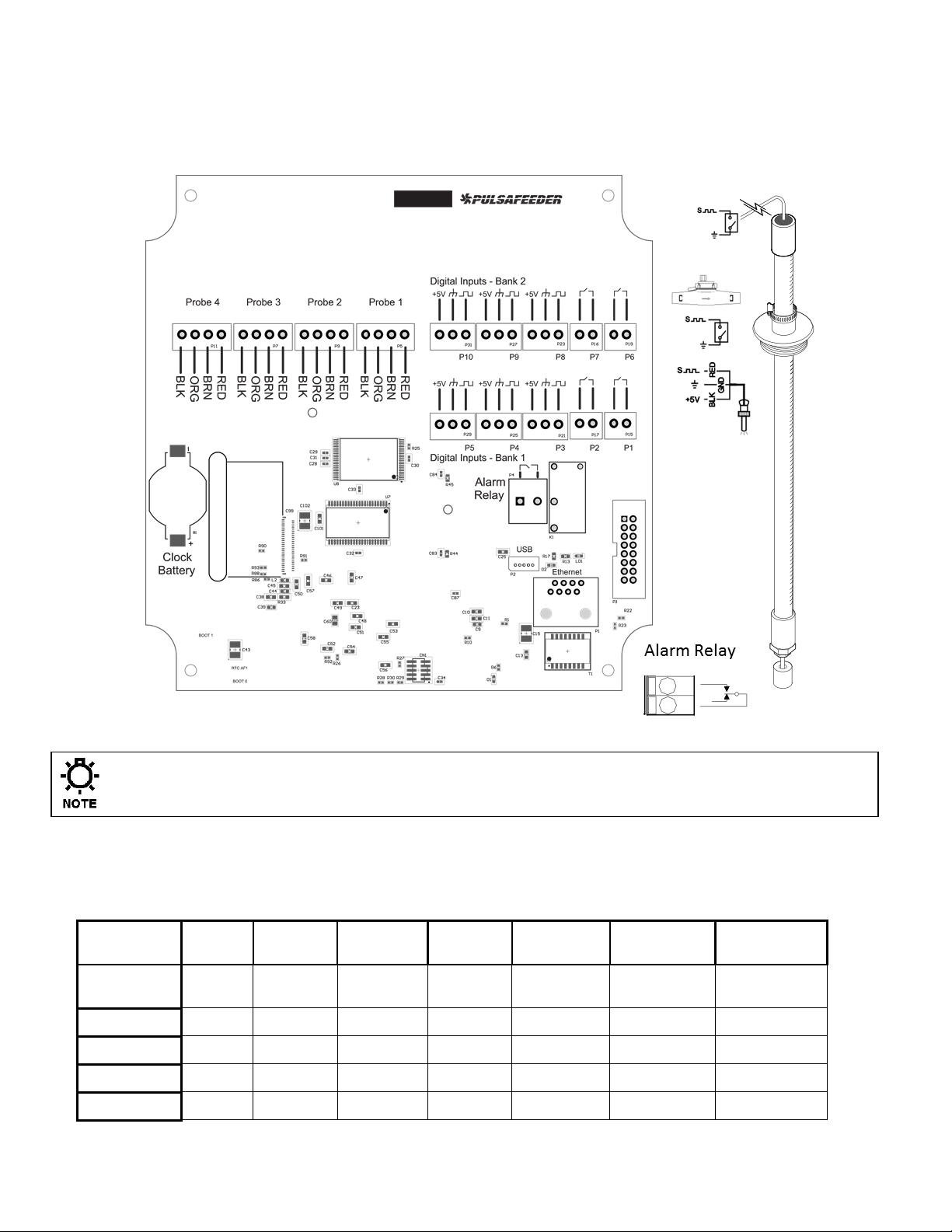
DIGITAL BOARD CONNECTIONS
Digital
Inputs
Input 1
Input 2
Input 3
Input 4
Input 5
Inputs 6 & 7
Inputs 8,9
and 10
Function
Flow
Switch
Drum
Level #1
Drum
Level #2
Drum
Level #3
Water
Meter
Water
Meter
Water Meter
Assignment
N/A
Timer #1
Timer #2
Timer #3
WM #1
WM #2 & 3
WM #4 to #6
Location
P1
P2
P3
P4
P5
P6 and P7
P8, P9, P10
Dry Contact
√ √ √ √ √ √ √
Hall Effect
√ √
The low voltage connections are found on the top board.
Use 22-24 AWG (,76 mm²) wire for: flow switch, drum levels, dry alarm, and water meter
connections. A recommended wire is OMNI cable DS92203. These signal wires must be
run separate from AC power lines.
Clock Battery # 09-710-04
Low voltage signal wires, e.g., water meter, must be run separate from AC power lines.
Digital Input assignments
There are 5 digital inputs on base conductivity models and up to 10 on featured models.
72-900-06 Rev. F
Page 11 of 38
Page 12

3.8 Flow Switch Input
It is recommended that a flow switch or auxiliary dry contact be used to make outputs
inoperative when the cooling tower is shut down. Connect detection wires to P1 to use
this interlock feature. This is active – closed: open = no flow; closed = flow.
If the controller does not have a flow switch, a jumper wire must be
connected across P1.
3.9 Sensor (probe) Connection Input
The controller is supplied with sensors prewired. Depending on the model, the
conductivity probe wires are connected to Probe 1, pH sensor on Probe 2, ORP sensor on
Probe 3, and Make up conductivity on Probe 4.
Always depressurize the unit prior to removing a sensor.
3.10 Water Meter Input
Connect the water meter to P5 on the top board. Some models have additional water
meters on P6 through P10. In order to wire a dry contact type water meter or contact
closure to a 3-port digital input, connect the two leads to the signal and ground ports.
3.11 Drum Level Input
The drum level connections are labeled as, P2 for Level 1, P3 for Level 2, and P4 for level
3. These are active closed: closed = low level; open = level is OK. The input can also be
reversed (NO or NC) in the programming.
3.12 4-20mA Output
The 4-20mA outputs, ordered separately, can be used to remotely measure any of the
controllers probe inputs and any of the 4-20mA inputs. Connect the 4-20mA receiving
equipment to the 4-20mA boards pins are marked + (positive) and – (negative). The
polarity must be observed for proper operation. The 4-20mA output current range is
approximately 0 mA to 24mA. Resistive load range should typically be 300 Ohms with a
max rating of 1200 Ohm.
3.13 4-20mA Input
Model dependent, MicroVision EX can support up to two 4-20mA analog inputs. The 420mA inputs, ordered separately, can be used to receive and data log signals from
sensors that transmit a 4-20mA output. Connect the 4-20mA equipment to the 4-20mA
boards pins are marked + (positive) and – (negative). The polarity must be observed for
proper operation.
Each 4-20mA analog input supports 2 wire loop or transmitter powered configurations.
Input resistance load is approximately 265 Ohms. Input voltage range is commonly 12V
or 24V. Up to 60V is permissible.
72-900-06 Rev. F
Page 12 of 38
Page 13

Tx
Pwr
Tx
Pwr
3.13.1 Fluorometer – Trace Chemical
The MicroVision EX can be optionally purchased panel mounted with a fluorometer, turner
LD2 or Pyxis ST-500 probe. From the factory, the probe comes prewired and calibrated.
Alternatively, the probe can be ordered separately, wired and programmed. Be sure to
observe the manufacturers wiring directions.
3.13.1.1 Turner Little Dipper™ 2
The turner is an inline fluorometer with a linear 4-20mA output which responds to trace
chemical. Typically is set to 4mA = 0 PPB and 20mA = 200 PPB probe has 4 wires; Red,
Black, Orange, and Brown. The red is the power supply voltage. Black is the Supply
ground. Orange is the positive current loop connection. Brown is the negative current loop
connection. The turner little dipper 2 requires an external power supply of 8-32 VDC (1W
Max)
72-900-06 Rev. F
Page 13 of 38
Page 14

3.13.1.2 Pyxis ST-500
The Pyxis ST-500 is also an inline fluorometer which outputs both a 4-20mA signal and a
RS-485 interface which responds to PTSA trace chemical. The ST-500 also has a 4-20mA
where 4mA = 0 PPB and 20mA = 200 PPB. Wiring the ST-500 is similar to the Little Dipper
2. The RS-485 bus is not used by the MicroVision EX (The blue and yellow wires). The
only wires necessary to terminate are power to the Pyxis and the 4-20mA loop (Brown or
white (4-20mA+) and Green (4-20mA-)). The clear wire should be connected to the
solution ground.
3.13.2 Calibrating PTSA Probe
4-20mA input probes require a 2 point calibration. In order to calibrate a Pyxis or Turner
inline fluorometer, navigate to the 4-20mA input in question. I.E. Menu -> Settings -> 420mA In 1. For a PTSA probe the units are PPB. Select Type->PPB. Select Back. Scroll
down to Calibrate. For a 2 point calibration you will need a low point and a high point. The
best way to calibrate a low point is to put the probe in deionized water, uncontaminated
with any PTSA. You should see ~4mA as the actual signal. Enter “0000” on the top line.
Before exiting this page the high point will need to be calibrated. This is ideally done in the
actual flow assembly. Place the probe in the flow allow solution to flow across the sensor
to purge any air bubbles out of the sensor. Take a sample with a handheld meter be sure
the mA signal on the controller is stable and enter the high point, the value measured by
the handheld. Alternatively, to calibrate the high point of the sensor, buffer solutions can
be used. Fully submerge the sensor in the known buffer ensure to expel air bubbles which
may have formed on the optics. The known buffer needs to be within the range of the
probes sensing capabilities. Ensure the mA output from the probe has stabilized on the
MicroVision EX under the actual reading. Enter the known value as the high point, upon
hitting enter on the last digit the value will be saved and your probe successfully calibrated.
3.14 Alarm Dry Contact Relay
The alarm dry contact activates for all system alarms and is a volt free signal. Use P4 to
connect the alarm reporting equipment. This relay will close when an alarm condition
exists and will open when no alarm conditions are present. This connection is intended to
be used to signal external process control equipment or indicators (low voltage DC
operated buzzers or lamps) when an alarm condition is present. This relay is not
protected by a fuse and should not be used to voltages above 48VDC.
72-900-06 Rev. F
Page 14 of 38
Page 15

FRONT PANEL DESCRIPTION
3.15 Keypad Operation
UP/DOWN - Dual function keys are used to move the select
(highlighted) box and to increase and decrease values.
O O - Soft keys used for various functions depending on the
currently displayed screen. The key’s function appears
above the key on the display.
3.16 Communications (Optional)
The MicroVision EX has a variety of cloud capable controllers. These controllers will ship
with a CAT5 cables with an RJ45 connection. To connect the MicroVision EX to PulsaLink,
Pulsafeeders cloud controller management software solution. The controller will need
internet access. Please terminate the provided RJ45 connection to an open internet port.
72-900-06 Rev. F
Page 15 of 38
Page 16

4. CONTROLLER PROGRAMMING
4.1 Menu Map
4.2 Menu Navigation
MicroVisionEX uses four front panel buttons to navigate through the different menus. Use
these buttons to move up and down within a list of options or move right and left to enter
or change parameter values. In some cases the MicroVisionEX display will prompt the user
to press the different buttons to assist you in selecting or changing data.
Some menus may display highlighted menu options or a checkmark () next to a menu
option. The highlighted menu option is used to indicate that another menu will be displayed
if this option is chosen. The checkmark indicates that a particular control mode has been
selected.
4.3 Home screen
The Home Screen displays the system readings and operating information. This screen is
displayed during normal operation when there are no alarm conditions on the MicroVisionEX.
If an alarm condition occurs an alarm message will flash on the screen. The LED’s to the
right of the display will also flash indicating an alarm has occurred.
The MicroVisionEX will return to this screen if no buttons are pressed for five minutes after
entering a menu.
72-900-06 Rev. F
Page 16 of 38
Page 17

4.4 Main Menu
The Main menu is the starting point for all subsequent programming menus.
Relay HOA – This menu allows for the control of the relay output states, either
manual off, or auto.
Configure – This menu allows for setting the time and date, display contrast, water
meter, etc.
Settings – This menu allows for setting the conductivity, pH and ORP configurations
Timers– This menu allows for setting the timers for the different feed modes.
Communications– This menu allows for exporting data, exporting settings,
importing settings and upgrading the O/S.
4.5 Relay HOA
From the HOA Outputs menu manually set the relay control outputs. This is useful for
servicing chemical pumps or troubleshooting electrical problems. First select the relay
output to be controlled then select the relay state.
Forcing the output to Auto may cause the control output to energize without warning.
4.6 Configure
From the Configure menu select from many different system configuration options.
Date/Time – Set the current date, date format, time, and time format.
Digital Inputs – Set the drum level settings, and water meter type and volume.
4-20mA Out- Activate or deactivate 4-20mA output options.
4-20mA In- Activate or deactivate 4-20mA input options.
Gal/Lit- Set the units that the controller displays.
Meter Totals- Display and/or reset the water meter totals.
Language – Change the controller displayed language.
Display Settings – Set the display, brightness, home screen display text, home
screen scroll rate, home screen alarm message size, and the display dampener.
Password – Set the user password.
Software Version – Displays the current software version.
Factory Restore – Restore the parameters to factory default
4.6.1 Date/Time
From the Date/Time menu set the date and time as well as the date and time display
formats.
Set Date – Set the current date.
Set Time – Set the current time.
Date Format – Pick the day/month/year format.
Time Format – Pick the 12-hour or 24-hour time of day format.
72-900-06 Rev. F
Page 17 of 38
Page 18

4.6.2 Digital Inputs
4.6.2.1 Drum Level
From the Drum Level menu select how the timer output will respond to a low drum level
indication. The available choices are to allow the pump to continue to run, or have the
pump stop when its drum level goes low. Drum level #1 is always assigned to timer #1,
Drum level #2 is always assigned to timer #2, and drum level #3 is always assigned to
timer #3.
Alarm Trigger – Program the drum level to go into alarm when the drum level
switch contact is either open or closed.
Action on Alarm – Program the drum level input to either turn off the timer relay
on alarm or allow it to keep the relay on in automatic mode.
When a drum level goes low the controller will go into alarm regardless of this
setting. Re-filling a low drum may cause the pump control output to energize without
warning.
4.6.2.2 Water Meter
From the Water Meter menu select what type of water meter the controller is attached to.
Once the meter type has been entered the next setting will be for the gallons/liters per
pulse or K-factor, depending on the meter type.
Dry contact or Hall-effect water meter- Once the type is selected enter the
resolution or volume per pulse or pulses per gal/lit for hall effect.
Gal/pulse or K factor – enter the setting for the water meter connected.
4.6.3 4-20mA Out and 4-20mA In
Activate or deactivate the 4-20mA output or input options in this screen. Analog inputs and
outputs are upgrade options for all models. To install analog signal options, first activate
them in this screen, then power the unit down and then install the signal modules as
described in the upgrade kit instructions. When the 4-20mA inputs or outputs are activated
they will have their own program settings in the “Settings” menu.
4.6.4 Gal/Lit
Select the unit of measure for the controller to display for the water meter settings.
4.6.5 Meter Totals
In the meter totals screen view the water meter total values and the date they were last
reset and reset the total values to zero in this screen.
4.6.6 Languages Menu
Select the language the controller programming displays.
English
Spanish
Portuguese
72-900-06 Rev. F
Page 18 of 38
Page 19

4.6.7 Display Settings
This menu is for setting how the controller display appears.
4.6.7.1 Brightness
Select this menu to set how bright the background is, Low, Medium, or High.
4.6.7.2 Display Line text
Select this menu to change what text is displayed on the two lines of the main home screen
display. (Pulsafeeder and MicroVision EX are the default)
4.6.7.3 Home Screen Display Scroll
Select this menu to set the speed that the home screen scrolls from displaying various
values, Low (30 seconds), Medium (10 seconds), or High (5 seconds), or OFF for no
scrolling of the main menu.
4.6.7.4 Display Alarm
Select this menu to set the size of the alarm messages that are displayed in the home
screen when they occur.
4.6.7.5 Display Dampener
The Display Dampener setting sets how often the actual conductivity reading is updated on
the Home Screen. This results in dampening of the controller response to sudden changes
in conductivity.
The controller takes a conductivity reading once every second. Increasing this value
above one second causes the controller to average the readings, hence, slowing down
the control functions.
4.6.8 Password Setting
The Controller has two Security Access Codes, each with different system privileges - an
Administrator and a User. An Administrator can access all functions of the controller. A
User level can only access those items selected by the administrator. A password level is
not required for access to the home menu.
Both passwords are active when Administrator level password is set. Conversely, both
passwords are inactive when the Administrator level password is set to 000000. Each
password consists of a six (6) digit numerical code.
The Administrator configures the following parameters to restrict User access to the
controller systems
The following is an example of the Security menu options:
Exit Home Screen = Limits access to only the Home Screen.
Relay HOA = Allows access to the Relay HOA menu.
Configure Menu = Allows access to the Configure menu.
Settings Menu = Allows access to the Settings menu.
Timer Menu = Allows access to the Timers menu.
72-900-06 Rev. F
Page 19 of 38
Page 20

Calibration = Allows access to "probe Cal".
Download = Allows the user to export the data files.
Upload = Allows the user to import program settings.
USB Settings = Allows the user to change the USB settings.
Factory Reset = Restricts access to the factory reset feature.
Once the password is set the controller will require a password to access any of the
menus. If the password is lost or unknown it will be necessary to call technical
service to gain access to the controller menus.
4.6.9 Software Version
From the Software Version screen view the current software that is running in the
MicroVision
EX
controller.
4.6.10 Factory Reset Function
The Factory Reset Function will reset all of its internal parameters to the factory default
values.
Be absolutely certain you want to reset all the parameters back to the factory
defaults. Once the reset takes place there is no way to retrieve the previous
parameters.
4.7 Settings
The Settings menu is for setting the control parameters for conductivity, pH and ORP.
4.7.1 Conductivity
Set point Type - A Set point is a setting at which the controller activates an output,
such as a solenoid valve or a metering pump on the relay outputs or dry contact
outputs. The type – Rising or Falling defines which side of the set-point the relay
activates. A Rising type means that the output activates when the input goes above
the set point. A Rising set point is commonly used in conductivity control where you
want to keep conductivity below a certain value. A Falling type activates the output
when the value goes below the set point.
Set point –This is the conductivity point where a bleed function will begin.
Differential – The differential setting controls when the bleed function stops. This
value subtracted from the conductivity set point causes the bleed function to stop.
Example: Rising Set point=1200, Differential=100, the bleed function begins when
the conductivity reaches 1200 and ends when the conductivity reaches 1100.
72-900-06 Rev. F
Page 20 of 38
Page 21

Limit Timer – Set this value to the maximum amount of time the bleed output can
Menu
Settings
Conductivity
Conductivity
1234 uS/cm
Back | Next
Probe Cal
stay energized before a Bleed Limit alarm is reported. If the next bleed cycle
completes without an alarm the alarm will clear itself on the next cycle. Setting the
limit timer value to 00:00 will turn off limiting function of the relay.
Limit Alarm- Use this option to turn the control relay off on a limit alarm, or to keep
it on in automatic mode during a limit alarm. (default is “keep relay on” for the bleed
relay)
Probe Calibration – Use this function to calibrate the probe.
Alarm Setp’t – Use this menu to specify the upper and lower values for alarm
reporting.
Settings Menu- When the settings menu is being displayed, probe control
operations stop until all settings changes are completed and
The conductivity probe is very sensitive to temperature changes. Allow the probe
roughly 10 minutes to adjust to the temperature of the test solution or sample.
Calibrating the probe without allowing the probe to equilibrate to the sample
temperature could result in erroneous controller conductivity readings.
Only use a calibration meter that incorporates temperature compensation when
performing a probe calibration.
4.7.1.1 Probe Calibration Conductivity
Because there are no metal electrodes to foul re-calibration is not required for the toroidal
probe on a regular basis. However, you may want to calibrate the probe initially to get a
base-line reading for future reference or to have the reading match a hand held tester.
There are two methods of probe calibration that can be used to calibrate this probe.
In-stream Calibration – In this method the probe is already installed in the
process flow and is currently reading conductivity. Be certain adequate flow (1
gallon/minute minimum) has been circulating around the probe for at least 15
minutes. This will ensure the probe temperature has stabilized and a more accurate
conductivity reading will be made.
Step 1 – Move to the Probe Calibration screen.
72-900-06 Rev. F
Page 21 of 38
Page 22

Step 2 – Draw a sample of the process flow water and measure the conductivity
using a calibrated meter. Be certain the meter being used to measure
conductivity is temperature compensated.
Do not allow the sample to sit for any length of time after being drawn as this may
cause the reading of the sample to be different from the probe.
Step 3 – Enter the calibrated conductivity value into the Probe Calibration screen.
If the conductivity reading varies more than 25 counts from the reading of the
calibration meter verify the sample temperature is within 1 C of the probe
temperature.
Step 4 – Return to the Home Screen and verify the proper conductivity reading is
displayed.
4.7.2 pH and ORP
From these menus configure the parameters that trigger the pH and ORP control output.
Additionally, the probe calibration, alarm set points, and the limit timer functions are also
configured in this section.
Set point Type - A Set point is a setting at which the controller activates an output,
such as a solenoid valve or a metering pump on the relay outputs or dry contact
outputs. The type – Rising or Falling defines which side of the set-point the relay
activates. A Rising type means that the output activates when the input goes above
the set point. A Rising set point is commonly used in pH control where it is desirable
to keep pH below a certain value. A Falling type activates the output when the
value goes below the set point. A common example of this is ORP control, where
maintaining a certain minimum level of an oxidizer in the system is required.
Set point –This is the point where a control relay will activate. Once the ph or ORP
has reached this value the control relay output will turn on.
Differential – The differential setting controls when the control relay deactivates.
This value subtracted from the set point causes the relay to stop.
Example: Set point=7.00, Differential=1.00, the pH begins when the pH reaches 7.0
and ends when the pH reaches 6.0.
Limit Timer – Set this value to the maximum amount of time the output can stay
energized before a pH or ORP Limit Alarm is reported. If the next control cycle
completes without an alarm the limit alarm will clear itself on the next cycle. Setting
this value to 00:00 turns off this function.
Limit Alarm- Use this option to turn the control relay off on a limit alarm or to keep
it on in automatic mode during a limit alarm. (default is “Turn relay off” for the pH
and ORP relay)
Probe Calibration – Use this function to calibrate the probe.
Alarm Setp’t – Use this menu to specify the upper and lower values for alarm
reporting.
72-900-06 Rev. F
Page 22 of 38
Page 23

Menu
Settings
pH
Probe Cal
pH Calibration
Actual 07.20 pH
Pt. 1 07.00 pH
The probe is very sensitive to temperature changes. Allow the probe roughly 5
minutes to adjust to the temperature of the test solution or sample. Calibrating the
probe without allowing the probe to equilibrate to the sample temperature could
result in erroneous controller readings.
4.7.2.1 pH and ORP Probe Calibration (1 point)
Probe Calibration – Use this function to calibrate the probe. Enter the calibrated
value based on the calibration method used. For both methods shown below the
actual reading from the probe is shown on the screen. This is the un-calibrated value
the controller is receiving from the sensor. If the actual value displayed in the
calibration screen is not close to the sample that the probe is actually in, or the
reading is changing significantly, the probe either needs to be cleaned or replaced, or
the solution the probe is in is no longer accurate. Typically ORP does not require a
calibration for most applications for that reason only pH is illustrated below.
In-Stream (Best Practice)
Begin with a clean sensor. With the pH or ORP sensor installed in the
system under normal operating conditions ensure flow is going across the
probe for at least five (5) minutes for temperature equilibrium.
Step 1 – Move to the Probe Calibration screen.
72-900-06 Rev. F
Page 23 of 38
Step 2 – Take a reading with a hand held tester from the sample valve on the
controllers flow assembly.
Step 3 – Observe that the actual reading displayed has stabilized then enter the
reading from the hand held tester as point 1. For the best results, this method
should be done with the system operating at, or within 1 pH unit, of the pH set
point.
Step 4 – Return to the Home Screen and verify the proper pH reading is
displayed.
Standard solution
Begin with a clean sensor, rinse the sensor with the standard solution to be
used for calibration purposes three (3) times, place the sensor in a
standard solution that represents the side of the pH scale for intended
control. For example, if the set point is above 7pH the standard should also
be above 7pH. With the sensor in the solution for at least five (5) minutes
for temperature equilibrium, observe that the actual value displayed has
stabilized and then enter the standard solution value as point 1.
Page 24

4.7.3 4-20mA Outputs (Optional Accessory)
4-20mA Out 1 = Cond.
9999 uS = 20.0 mA
0000 uS = 4.0 mA
Min. diff. = 1000 uS
Next
To enable 4-20mA output, see sec 4.6.3. The output will then be configurable from the
settings page. First set the type setting to the sensor input that the 4-20mA output will
track, any probe types can be configured. Then enter the sensor reading ranges to scale
the 4-20mA output to. Any sensor value can be entered for the 20.0 and 4.0mA ranges.
The actual output can then be adjusted from 20mA to 24mA and from 0mA to 5mA for
calibration to the receiving device.
4.7.4 4-20mA Inputs (Optional Accessory)
To enable a 4-20mA input, see sec 4.6.3. Once the board is enabled device will appear in
the settings page. Here you can setup the peripheral. To setup you must configure the type
and calibrate the input. To configure the type select the mode which resembles your
application. Then you must calibrate the input, depending on the input type, you may need
buffer solutions to do this. Hold the input device in a low state, enter the correlating value
in the controller on the top line, do not exit the setup until the next point has been
calibrated, otherwise you will get an error. Place the input in a high state and enter the
correlating value in the controller. Your input should now be set-up. If you still get an error
exit out and start over. If you wanted to have any timers trigger based on the 4-20mA
input you can configure a set point control timer.
4.8 Timers - Modes
From this menu pick the mode that the timer will follow.
Pulse Timer – Runs the timer based in inputs from a water meter.
Percent Timer – Sets the Timer to run on a repeating cycle. Set the Cycle time
period and percentage of the cycle time period to run for. Example: Cycle
Time=60minutes, % Minutes to run=10, the timer will run for 10% of 60 minutes, or
6 minutes every 60 minutes.
28-day timer- Runs the timer based on a calendar schedule of specific times, days,
and weeks. Typically used to add biocides
72-900-06 Rev. F
Page 24 of 38
% Post Bleed – Runs the timer for a percentage of the bleed time when the bleed
control stops.
Page 25

Limit Timer – Set this value to the maximum amount of time for the timer to run
while the bleed function is running. If this time is exceeded the controller will go into
alarm and the timer control output will de-energize.
Alarm – The timer activates based on system alarms for powering sirens, lights or
sending remote signals.
Set-point Control – This timer behaves like a conductivity, pH and ORP relay. The
relay will turn on and off based on a probe input set-point.
Disabled – The timer does not activate.
4.8.1 Timers – Pulse Timer
From this menu configure how the timer will run while in pulse timer mode. This mode uses
the water meter input to cause a counter to accumulate a certain volume of water before
the timer is activated. Once the accumulated volume is reached, the timer is activated for
the programmed Feed Time.
Feed Time – Set this value to the amount of time for the timer to run when the
water meter accumulator count reaches the accumulator set.
Accumulator Set – Set this value to the amount of water that needs to accumulate
prior to a timer feed time. The units will be in gallons or liters depending on what
units are set in the configure menu.
Accumulator Count – This is the current running count of the water meter
accumulator.
4.8.2 Timers – Percent Timer
From this menu configure the timer to operate on a percentage of a fixed cycle time
repeatedly.
Example:
Cycle Time=60minutes.
% Minutes to run=10%
In this example the timer will feed for 10% of 60 minutes, or 6 minutes every 60
minutes.
4.8.3 Timers - 28 day (Biocide Timer)
From this menu configure how often and the duration for the biocide 28-day timer to run.
This controller can also perform a pre-bleed, using a conductivity minimum with a fixed
time, and a bleed-lockout function for each biocide feed program. Each 28 day timer has
four (4) programs (Program A to D) with individually programmable settings as follows:
Days/Weeks – Set the days and weeks for the timer to run.
Start Time – Set the time of day for the timer to begin. If a pre-bleed is
programmed, this is the time that the pre-bleed starts. Setting the value to 00:00
means the start time is ignored.
Feed Time – Set this value to the amount of time for the timer to activate the timer
control relay for each start time.
72-900-06 Rev. F
Page 25 of 38
Page 26

Pre-Bleed – Set the pre-bleed time to the maximum amount of time for the pre-
bleed function to force a bleed cycle without reaching the conductivity minimum. Set
the conductivity minimum to the value for the conductivity to reach before the bleed
cycle finishes and the biocide feed time.
Bleed Lockout – Set this value to the amount of time to lock-out a bleed function
during (and after if set longer then the feed time) a biocide feed cycle.
28 day timer programs (A to D) cannot be set to run at the same time, week and
day. If two timers have the same run times only the first program, in alphabetical
order, set will run (example if A and B are the same, only A will run.)
4.8.4 Timers – % Post Bleed
From this menu configure how the timer will run while in percent post bleed mode. This
mode uses the bleed time to calculate the run time based on a user defined percentage
setting.
Percentage – Set this value to the amount of time (as a percentage) for the timer
to run after a bleed function has completed.
Example: % of Bleed=25%, the most recent bleed cycle took 20 minutes, the timer
will now feed for 25% of 20 minutes, or 5 minutes.
Limit Time – Set this value to the maximum amount of time to allow the timer to
run after a bleed cycle has completed. Setting the timer to 00:00 turns off this
function.
4.8.5 Timers – Limit Timer (Bleed and Feed)
From this menu configure how the timer will run with the bleed relay. This mode activates
the timer at the same time as the bleed time up to a user defined maximum time. Set this
value to the maximum amount of time to allow the timer to run for during bleed cycle.
Setting the limit timer value to 00:00 will turn off limiting function of the relay.
4.8.6 Timers – Alarm
In this mode the timer activates with any system alarm condition.
4.8.7 Timers – Set Point Control Mode
A set point control mode time can be pointed to any of the probe inputs. Programming the
timer mode is identical to setting up a probe. This timer mode is only an option on timer 1,
2, and 3. One of the core functions of this timer mode is to feed chemical in response to a
4-20mA probe time, a PPB or PPM type input.
Set point Type - A Set point is a setting at which the controller activates an output,
such as a solenoid valve or a metering pump on the relay outputs or dry contact
outputs. The type – Rising or Falling defines which side of the set-point the relay
activates. A Rising type means that the output activates when the input goes above
the set point. A Rising set point is commonly used in conductivity control where you
want to keep conductivity below a certain value. A Falling type activates the output
when the value goes below the set point.
Set point –This is the defined point where a relay will energize.
Differential – The differential setting controls the offset which the relay will remain
energized, once the offset is exceeded the correlating relay will de-energize.
72-900-06 Rev. F
Page 26 of 38
Page 27

Limit Timer – Set this value to the maximum amount of time relay will remain on
until an alarm is triggered. Setting the value to 00:00 disables the timer.
Limit Alarm- Use this option to turn the control relay off on a limit alarm, or to keep
it on in automatic mode during a limit alarm. (default is “keep relay on”)
Alarm Setp’t – Use this menu to specify the upper and lower values for alarm
reporting.
4.8.8 Timers – Disabled (Default)
In this mode the timer does not activate other than by the use of the HOA function.
4.8.9 Timers – Bio Tracking (In All Timer Modes)
From this menu configure how the timer will respond when a 28-day timers Feed Time
setting is running.
Skip – Choose this option for the timer to skip a feed cycle if a 28 day biocide timer
happens to be feeding.
None – Choose this option for the timer to run regardless of what the biocide feed
cycles are doing.
Any timer feed time that was skipped due to a 28 day biocide feed cycle will not
be added to the next timer feed cycle.
4.9 Communications
The controller has two primary methods of communications, a direct USB collection port
and an Ethernet port.
4.10 USB
When a USB flash drive is inserted into the USB cable the user can take certain
actions. If a password has been entered into the controller, the user must first enter
the required code to access the USB options screen.
Export Data Log
The controllers data log history file can be downloaded to the USB flash drive
in CSV format.
Export Config File
The controllers programming and set points can be down loaded for
duplication of the program on other MicroVisionEX controllers or as a record of
the current settings.
Import Config file
The controllers programming and set points can be uploaded for duplication of
the program from other MicroVisionEX controllers.
Erase Data Log
Use this function to reset the controllers data log records. The current data log
will be erased and cannot be recovered
Data Log Name
Use this setting to give the exported data files a unique file name for each
controller. The file name length is fixed at 16 characters. However, it is
72-900-06 Rev. F
Page 27 of 38
Page 28

possible to use “*” symbols in the name to create spaces. The default name
is: DataLogFile***** this produces CSV file named DataLogFile0.csv
Data Log Interval: Use this setting to define how much data the controller
will store. Options are “Custom”, 30 days, 60 days, 90 days, 120 days, 1 year
or 2 years. All Data Log Interval ranges still record controller data every 1
minute; however the “custom” setting allows for a range from 2 to 120
minutes to make exporting the data file to a USB drive or downloading faster.
Because the custom range always uses the same size memory block it stores
various ranges of data.
Example:
Custom range @ 2 Minutes = 60 Days
Custom range @ 120 minutes = 9.8 Years
Normal data log interval settings create a file that could be as large as 350MB
in size. The custom range settings create a file that could be as large as
40MB.
In order to access the data stored on the controller remotely the data
log interval must be set in either 30 days @ 1 minute or any setting in
the custom menu.
Changing the Data log interval erases the existing data log file in the controller
to create a new one. To avoid losing data, download the current log file before
changing this setting.
Operating System Upgrade
The controllers operating software can be updated in the field to the most
current version available. To upgrade the OS install the OS file on a USB drive
and plug the drive into the controller. Make a note of all controller program
settings, and then power the controller down. Press the Arrow up key and the
lower left navigation key (upper right and lower left keys diagonal from each
other) on the front panel and hold them down. Next power the controller up.
Wait approximately 30 to 60 seconds, the controllers display will come on and
the new OS will be installed. Before programming erase the data log and
perform a factory reset. Reprogram the controller settings.
4.10.1 USB Graphing Tool
The MircoVision EX data log file is output as a CSV file. This file can be opened for
easy viewing and digestion of data using our provided graphic tool. Visit:
www.pulsatron.com/support/pulsaworks to download.
4.10.2 USB Data log Timer and Tamper Codes:
Timer Modes
1792 = Disabled
1536 = Alarm
1280 = Set Point control
1024 = Limit Timer
72-900-06 Rev. F
Page 28 of 38
Page 29

768 = % Post Bleed Timer
512 = 28 day Biocide Timer
256 = Percent Timer
0 = Water Meter Pulse Timer
TMPR Column:
The tamper column will nominally appear as 0. If the unit is tampered
with you will see a 1 in the tamper column. Any other value indicates a
power cycle of the unit.
4.11 Ethernet (Optional)
On a model equipped with Ethernet communications, the MicroVisionEX controller when
networked via the Ethernet cable and an application appropriate network adapter the user
will able access the controller, download data from the unit and upload programming
changes via our online PulsaLink portal.
4.11.1 Programming your controller PulsaLink
Once the controller’s RJ45 connector has been wired to a reliable Ethernet connection. The
controller has a token which needs to be programmed. After setting the controller token to
a non-zero value (Menu->Communications->Networking->Token) power cycle the
controller to start communicating on PulsaLink. The default token is 000-000-001. See the
PulsaLink user manual for more information.
4.11.2 Setting Up Your Controller on PulsaLink
In order to access your controller online you will need to go to
“https://www.pulsalink.net/login”. Contact your company administrator if you need to be
setup with an account. An administrator needs to grant access to users to each controller.
72-900-06 Rev. F
Page 29 of 38
Page 30

5. FACTORY DEFAULTS
DEFAULTS
SYSTEM CONDUCTIVITY SCALE
0-9,999 S/CM
Set point Type
RISING
Set point
1500 µS/CM
Set point Differential
50 µS/CM
High Alarm
1700 µS/CM
Low Alarm
1300 µS/CM
Limit Timer
00:00 (disabled)
MAKE-UP CONDUCTIVITY SCALE
0-10,000 S/CM
Set point Format
CYCLES
Set point Scale
0-2000 S/CM
Set point Ranges
0-400 / 401-800 / 801-1200 / 1201-1600 / 1601
Set point Range Set points
6.0 / 5.0 / 4.0 / 3.0 / 2.0 Cycles
Set point Differential
40 µS/CM
High Alarm
840 µS/CM
Low Alarm
360 µS/CM
SYSTEM pH SCALE
0-14 pH
Set point Type
Rising
Rising Set point
7.8 pH
Set point Differential
0.2 pH
High Alarm
8.3 pH
Low Alarm
6.3 pH
Limit Timer
01:30
SYSTEM ORP SCALE
-2000-+2000 mV
Set point Type
FALLING/LOW
Set point
400 mV
Set point Differential
50 mV
High Alarm
500 mV
Low Alarm
300 mV
Limit Timer
01:30
4-20mA INPUT
NONE
Units
NONE
4-20mA OUTPUT
0-20 mA
Type
None
LEVEL INPUT
Type
Level
Keep Relay on
FLOW INPUT
Type
Flow
TIMER
Type
DISABLED
TIMER: LIMIT
Run Time
01:30 HH:MM
72-900-06 Rev. F
Page 30 of 38
Page 31

TIMER: PERCENT
Percent
0%
Percent Minutes
10
TIMER: PERCENT POST BLEED
Bleed Percent
0%
Maximum Time
01:30 HH:MM
TIMER: PULSE
Run Time
00:30 MM:SS
Pulse Set
10
Water Meter
One
TIMER: 28-DAY
Run Time
01:30 HH:MM
Lock Out
00:00 HH:MM
Pre Bleed
00:00 HH:MM
Conductivity Minimum
0 S/CM
Program: Start Time
00:00 HH:MM
Program: Week
EVERY WEEK
Program: Day
NO DAY
WATER METER
Gallons per Pulse
100
Scroll rate
High (3 seconds)
SECURITY
Passwords
(NONE)
72-900-06 Rev. F
Page 31 of 38
Page 32

6. TROUBLESHOOTING GUIDE
Symptom
Probable Cause
Possible Solution
Controller does not
power up.
No power supplied to
controller.
Insure that correct voltage is supplied to
controller.
Check circuit breaker supplying power to
the controller.
Fuse is blown.
check/replace fuses (see page 9)
Ribbon cable.
Check ribbon cable connecting upper and
lower pc boards inside controller.
Controller displays
“Flow Switch Alarm”
alarm message.
No flow thru flow
assembly.
Insure there is enough water flow through
the assembly. At least 1 GPM (3.8 LPM) of
flow.
Flow switch wiring or
connector loose.
Check flow switch connections
Flow switch stuck.
Clean flow switch sensor mechanicals.
Flow assembly clogged.
Clean inside flow assembly.
Flow switch input jumper
missing.
Install jumper if flow switch is not used.
Controller displays "
Limit" alarm message.
Programmed limit timer
set too short.
Adjust limit timer value to longer duration
Clogged bleed valve or
drain.
Clean valve or drain.
Faulty bleed valve.
Replace bleed valve.
Controller displays
"Probe Comm" alarm
message.
probe wiring or connector
loose.
Check probe connections
Bad Conductivity probe
Replace probe.
Controller displays
"Bleed Limit" alarm
message.
Conductivity Limit timer
set too short.
Adjust limit timer.
Bleed valve/drain failure.
Clear obstruction around drain.
Conductivity, pH or
ORP reading on
controller does not
match portable handheld reading.
reading is within
specification.
Due to variations in hand-held meters,
standard solutions, temperature
compensation, and the controller’s accuracy
of +/- 2%, the reading on the controller
may not match that of your hand-held
72-900-06 Rev. F
Page 32 of 38
Page 33

7. MAINTENANCE
FUSE
TYPE
F1 & F3
5 X 20mm, 8A, 250V (Output power)
F2
5 x 20mm, 1A 250 V (Input power)
The only recommended maintenance required on the controller is periodic inspection of
the conductivity sensor every 6 months. It is recommended to establish a regular
maintenance schedule designed to meet the needs of each particular application. All
other service should be performed by factory authorized personnel only. Modifications
to or tampering with the circuit level components makes all warranties, written or
implied, and/or manufacturer’s responsibility for this controller, null and void.
DISCONNECT POWER BEFORE OPENING THE UNIT TO ACCESS FUSES. MAKE SURE
THAT REPLACEMENT FUSES ARE OF SAME TYPE TO MAINTAIN SAFETY APPROVALS.
ALWAYS DEPRESSURIZE UNIT BEFORE REMOVING PROBES
7.1 Conductivity Sensor removal and cleaning
To remove the conductivity sensor from its tee for cleaning:
1. Remove power to the system.
2. Remove pressure from the system prior to unscrewing the sensor by closing the hand
valves located before and after flow assembly.
3. Open the sample port; this will facilitate removal of sensor.
4. Unscrew the coupling nut.
5. Remove the sensor.
To clean conductivity sensor:
1. Wipe the sensor with a clean cloth.
7.2 pH sensor Information
The combination pH sensor supplied with your controller is designed for maximum
reliability, accuracy, and ease of use. The reference half-cell is sealed and non-refillable.
The sensor is shipped with a protective boot or bottle filled with a junction wetting agent.
7.2.1 Preparation
Remove the lower portion of the protective boot and rinse the sensor tip with tap water. It
is possible that air bubbles may have migrated into the pH sensitive bulb during shipment.
The sensor is unable to function with air in the bulb. To remove air, gently shake the sensor
downward in the same manner as a clinical thermometer. Prior to first usage or after longterm storage, immerse the lower end of the sensor in tap water for thirty minutes. This
hydrates the pH bulb and prepares the liquid junction for contact with the test solution.
Occasionally during long-term storage or shipment, the sensor may develop a film on the
pH bulb. The film may be removed by following sensor cleaning instructions.
72-900-06 Rev. F
Page 33 of 38
Page 34

7.2.2 Sensor Storage
To maintain response, sensors should always remain wet. The preferred storage solution is
pH 4.0 buffer with saturated KCl added. Tap water will suffice for short term storage.
Do not soak in distilled water. The supplied storage boot or bottle will provide an ideal
chamber for lengthy storage
7.2.3 Sensor Cleaning
Sensors which are mechanically intact can often be restored to full response by the
following procedures:
1. Inorganic Scale Deposits. Dissolve the deposit by immersing the sensor first in 0.1M HCl
(hydrochloric acid), then in 0.1M NaOH (sodium hydroxide), and again in 0.1M HCl. Each
immersion should be for a 5-minute period.
2. Organic Oil or Grease Films. Wash sensor tip in a liquid detergent and water. If film is
known to be soluble in a particular organic solvent, wash with this solvent. Rinse sensor tip
in tap water.
If these procedures fail to rejuvenate the sensor, the problem is most likely a clogged liquid
junction. Cleaning the liquid junction involves heating a diluted KCl (Potassium Chloride)
solution to 60-80°C (139-176°F). Place sensor tip in the heated KCl solution for
approximately ten minutes. Allow the sensor to cool while immersed in the solution before
re-testing. If these steps fail to improve the sensor response, replace the sensor.
7.3 ORP Sensor Information
The ORP option provides monitoring and control with a control setpoint in millivolts (mV).
7.3.1 ORP Maintenance and Troubleshooting
ORP standard buffers of 100mV and 465mV are readily available, making it easy to
standardize ORP systems against buffers. Like pH sensors, ORP sensors are subjected to
coating and abrasion by the measured liquid and, in certain instances, are “poisoned” by
chemicals which may be present if the system goes out of control. To improve the reliability
of ORP measurement and control, the following is a means of testing sensors in solutions of
standard potential, which will determine if sensors are responding correctly or need
maintenance attention.
7.3.2 Testing ORP Sensor
Solution A: Use sufficient 100mV buffer to immerse sensors. Potential should be within +/-
10.
Solution B: Remove sensors and rinse thoroughly with water. Immerse sensors in 465mV
solution. There should be a rapid response.
The millivolt difference between the two solutions is theoretically 365mV. The absolute
values may shift upward or downward a few millivolts due to slight variations from
theoretical potential by the reference sensor.
If system potentials are correct, flush sensors with deionized water and measure the liquid
in question. If incorrect by more than 10 mV, sensors should be cleaned with aqua regia
(three volumes hydrochloric acid, one volume concentrated nitric acid.) Repeat above tests.
Once satisfactory readings are obtained, install sensors and make measurements of liquid
in question.
72-900-06 Rev. F
Page 34 of 38
Page 35

Controller
Enclosure
IP65
Power supply
120 or 220 VAC; 50/60Hz.
Reading Accuracy
+/- 2% at point of measure
Maximum relay output
current
120 VAC: 8 A Resistive/General
use.4LRA/4FLA,1/10HP (motors)
220 VAC: 8 A Resistive/General
use. Not rated for motors
Probe
Maximum temperature
122° F (50°C)
Temperature compensation
range
32°F – 122°F (0° – 50°C)
Maximum pressure
125 PSI (8,6 BAR)
Probe type
Toroidal Conductivity, standard
pH and ORP
Maximum cable length
100 Feet (30,5 Meters)
Materials of construction
Polypropylene
Conductivity reading
0-9999 uS/cm; 1 uS/cm
increments
pH reading
0.00 to 14.00
ORP
-2000mV to +2000mV
Flow Switch
Maximum temperature
127°F (52°C)
Maximum pressure
125 PSI (8,6 BAR)
Activate flow rate
Approximately 1 GPM (3,785
LPM)
Materials of construction
PVC and Glass filled
Polypropylene
Use proper handling procedures including rubber gloves, eye protection and
protective clothing, when handling any acid solution.
7.3.3 Flow Sensor
The Flow Sensor uses differential pressure to cause a shuttle to rise and magnetically
activate a reed switch. Occasionally this assembly may become fouled, preventing the
shuttle from rising and/or falling.
To clean the assembly:
1. Close isolation valves and relieve system pressure from the flow assembly.
2. Remove flow cap by loosening retaining nut. Remove flow cap from flow body by pulling
straight out.
3. Remove red shuttle by pulling straight out. Note post shuttle rides on.
4. Clean all internal surfaces of flow body with soft bristle bottle brush. Be careful of the
post that the shuttle rides on, its surfaces must be clean, but do not break it while
cleaning.
5. Clean shuttle exterior surfaces and shuttle bore with a soft brush. You may use a mild
dish soap if desired. Flush well before re-installing.
6. Re-install shuttle and attach flow cap. Open isolation valves. Check for leaks.
8. SPECIFICATIONS
72-900-06 Rev. F
Page 35 of 38
Page 36

9. FORSEABLE MISUSE
The unit has many relays which can be programmed to operate on a variety of inputs and
timers. It is important to verify the system is set up properly through testing, and that
relays are actuated by the correct timer or input. It is important to verify all unit readings
match a known value. Operating outside design intent may cause hazard. Connecting
receptacles to unapproved hardware, i.e. drills, power tools, motor driven pumps, may
cause a hazard. Use only as directed. Unit has been designed for cooling tower
applications and any other application should be discussed with the factory prior to install.
Do not operate off of another controller. Do not use with extension cords.
72-900-06 Rev. F
Page 36 of 38
Page 37

10. MOUNTING HOLE PATTERN (Footprint)
72-900-06 Rev. F
Page 37 of 38
Page 38

Factory Service Policy
USA
Pulsafeeder, Inc.
27101 Airport Rd.
Punta Gorda, FL 33982
USA
(941) 575-3800
www.pulsatron.com
European Union (EU)
Pulsafeeder-Europe
Via Kennedy, 12-20090
Segrate—Milano– Italy
The MicroVisionEX is a state of the art microprocessor based controller. If you are experiencing
a problem with this instrument, first consult the troubleshooting guide in this manual. If the
problem is not covered or cannot be solved, contact Technical Services for assistance:
Trained technicians are available to diagnose your problem and arrange a solution. Solutions
may include purchase of replacement parts or returning the controller to the factory for
inspection and repair. All returns require a Return Authorization number to be issued by
Pulsafeeder. Parts purchased to correct a warranty issue may be credited after an examination
of original parts by Pulsafeeder. Warranty parts returned as defective which test good will be
sent back freight collect. No credit will be issued on any replacement electronic parts.
Any modifications or out-of-warranty repairs will be subject to bench fees and costs associated
with replacement parts.
Warranty
Pulsafeeder, Inc. warrants control systems of its manufacture to be free of defects in material or
workmanship. Liability under this policy extends for 24 months from date of shipment including
the toroidal sensor. Electrodes/probes other than the toroidal conductivity sensor are considered
maintenance items and as such are warranted for six (6) months from the date of shipment of
the controller. Electrodes/probes purchased as spare parts are warranted for 90 days from date
of shipment. The manufacturer's liability is limited to repair or replacement of any failed
equipment or part, which is proven defective in material or workmanship upon completion of the
manufacturer's examination. This warranty does not include removal or installation costs and in
no event shall the manufacturer's liability exceed the selling price of such equipment or part.
The manufacturer disclaims all liability for damage to its products through improper installation,
maintenance, use, or attempts to operate such products beyond their functional capacity,
intentionally or otherwise, or any unauthorized repair. The manufacturer is not responsible for
consequential or other damages, injuries, or expense incurred through the use of its products.
The above warranty is in lieu of any other warranty, whether expressed or implied. The
manufacturer makes no warranty of fitness or merchantability. No agent of ours is authorized to
provide any warranty other than the above.
72-900-06 Rev. F
Page 38 of 38
PULSAFEEDER INC. (SPO)
27101 AIRPORT ROAD
PUNTA GORDA, FL 33982
941-575-3800
 Loading...