

Page 1
PULSAlarm
Leak Detection
Vacuum and Pressure Options
For PULSA Series Metering Pumps
Models 680, 880, 7120, 7440, 7660, and 8480
Installation, Operation & Maintenance Instruction
Bulletin #: IOM–PSVLD-03 Rv B
ENGINEERED PUMP OPERATIONS
2883 Brighton Henrietta Townline Road
Rochester, New York, 14623
Telephone (585) 292-8000
Fax (585) 424-5619
www.pulsa.com E-mail:pulsa@idexcorp.com
Manufacturers of Quality Pumps,
Controls and Systems
Page 2

Pulsafeeder Factory Service Policy
Should you experience a problem with your Pulsafeeder pump, first consult the troubleshooting
guide in your operation and maintenance manual. If the problem is not covered or cannot be
solved, please contact your local Pulsafeeder Sales Representative, or Technical Services
Department for further assistance.
Trained technicians are available to diagnose your problem and arrange a solution. Solutions
may include purchase of replacement parts or returning the unit to the factory for inspection and
repair. All returns require a Return Authorization number to be issued by Pulsafeeder. Parts
purchased to correct a warranty issue may be credited after an examination of original parts by
Pulsafeeder. Warranty parts returned as defective that test good will be sent back freight collect.
No credit will be issued on any replacement electronic parts.
Any modifications or out-of-warranty repairs will be subject to bench fees and costs associated
with replacement parts.
Safety Considerations:
1. Read and understand all related instructions and documentation before attempting to
install or maintain this equipment
2. Observe all special instructions, notes, and cautions.
3. Act with care and exercise good common sense and judgment during all installation,
adjustment, and maintenance procedures.
4. Ensure that all safety and work procedures and standards that are applicable to your
company and facility are followed during the installation, maintenance, and operation of
this equipment.
4-27-2007 Rev B – change material references to “PTFE”
Notice
Information and specifications in this document are subject to change without notice.
Copyright
Copyright © 2004, 2006 Pulsafeeder, Inc. All rights reserved.
Information in this document is subject to change without notice. No part of this publication may be
reproduced, stored in a retrieval system or transmitted in any form or any means electronic or mechanical,
including photocopying and recording for any purpose other than the purchaser’s personal use without the
written permission of Pulsafeeder, Inc.
Trademarks
Pulsa Series® and PULSAlarm® are registered trademarks of Pulsafeeder, Inc.
2
Page 3

Table of Contents
1. S
YSTEM INFORMATION
1.1 Description and Theory of Operation...............................................................5
1.2 PULSAlarm Reagent Head..............................................................................6
1.3 PULSAlarm Leak Detection Diaphragm ..........................................................6
1.4 Diaphragm Construction..................................................................................7
2. E
LECTRICAL
3. S
ETUP FOR VACUUM SYSTEM
4. S
ETUP FOR PRESSURE
.............................................................................................................. 8
...............................................................................................5
..................................................................................... 9
..............................................................................................10
4.1 Pressure fill chamber.......................................................................................14
5. M
AINTENANCE
........................................................................................................... 16
5.1 Switch Setpoint Adjustment.............................................................................16
5.2 PULSAlarm Diaphragm Maintenance..............................................................17
5.2.1 PULSAlarm Diaphragm Removal.............................................................. 17
5.2.2 Inspection.................................................................................................. 18
5.2.3 PULSAlarm Diaphragm Reinstallation ...................................................... 18
5.3 Leak Detection system conversion ..................................................................19
6. S
ILICONE FLUID
MSDS.............................................................................................. 19
3
Page 4

Conventions:
.
A
WARNING DEFINES A CONDITION THAT COULD CAUSE DAMAGE TO BOTH THE
EQUIPMENT AND THE PERSONNEL OPERATING IT. PAY CLOSE ATTENTION TO ANY
WARNING
Notes are general information meant to make operating the equipment easier.
.
4
Page 5

For information on overall pump operation and maintenance, refer to the
Installation, Operation, and Maintenance manual specific to the model of pump in
question. The information in this bulletin pertains only to the PULSAlarm leak
detection system supplied as an option on Pulsafeeder PULSA Series pumps.
1. System Information
1.1 Description and Theory of Operation
The PULSAlarm leak detection system utilizes a two-layer PTFE diaphragm, coupled to a pressure
or vacuum switch.
For the vacuum-based option, a vacuum is drawn between the two layers of the diaphragm
assembly. During normal operation, vacuum is maintained. If there is a failure of either layer of
the diaphragm, the vacuum is lost. When the vacuum reaches a set value, the sensing switch is
trigger to signal an alarm. This system allows for simple setup, however the vacuum will leak
down over time under normal conditions. The system will need to have this vacuum occasionally
renewed during operation.
For the pressure-based option, the system is initially primed by filling the void within the detection
assembly and between the diaphragm layers with a barrier fluid. The setup process then bleeds
excess fluid from between the diaphragm layers until they are in close contact. The system operates
as follows:
During normal pump operation, the two layers of the PTFE diaphragm bear directly against one
another, and there is no pressure generated between the two layers. The sensing system monitors
the space between the layers, which will remain at zero pressure as long as the diaphragm layers
remain undamaged.
In the event of a failure of either layer of the diaphragm, liquid will enter the space between the two
layers. This liquid will be either the hydraulic oil (if the rear layer fails) or the pumped fluid (if the
front layer fails). As the pump operates, this liquid will generate pressure between the layers of the
diaphragm that will then be transferred outwards by the barrier fluid. This fluid will create pressure
against the pressure switch. This switch has a trip point of 5 psi (0.34 bar). When this pressure is
reached the switch will operate. The pressure system requires a more complex setup procedure,
however once operational it should require no further maintenance or operator interaction.
The output of the switch on either system (both normally closed and normally open connections are
available) can then signal the failure of the diaphragm. It is recommended that the pump be
stopped in the event a leak is detected. Immediate attention to the problem, followed by cleanup
and appropriate maintenance, will avoid further damage to the pump.
The barrier fluid used with the pressure-based system should be chosen for compatibility with the
process and environmental conditions. The fluid chosen should have as low a viscosity as possible
to aid in priming the system. Water can be used, and ethylene or propylene glycol can be added for
corrosion and temperature protection. Thin oils such as silicone oil or mineral oil can also be used.
Liquids of higher viscosity will extend the time required to properly prime the system. Thinner
liquids will allow for faster setup. Pulsafeeder supplies as standard a low viscosity silicone oil.
System identification (vacuum or pressure based) is noted on the switch cover nameplate, and also
on your Pulsa Series pump Specification Data Sheet.
5
Page 6
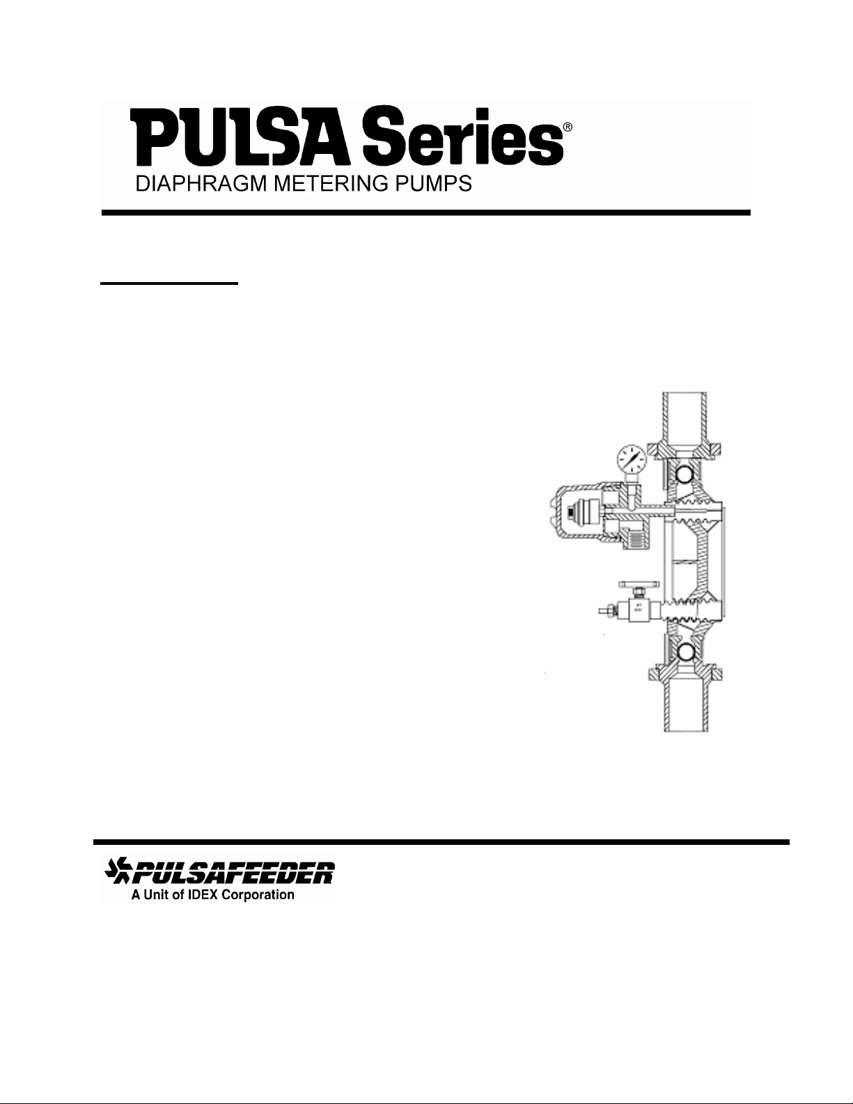
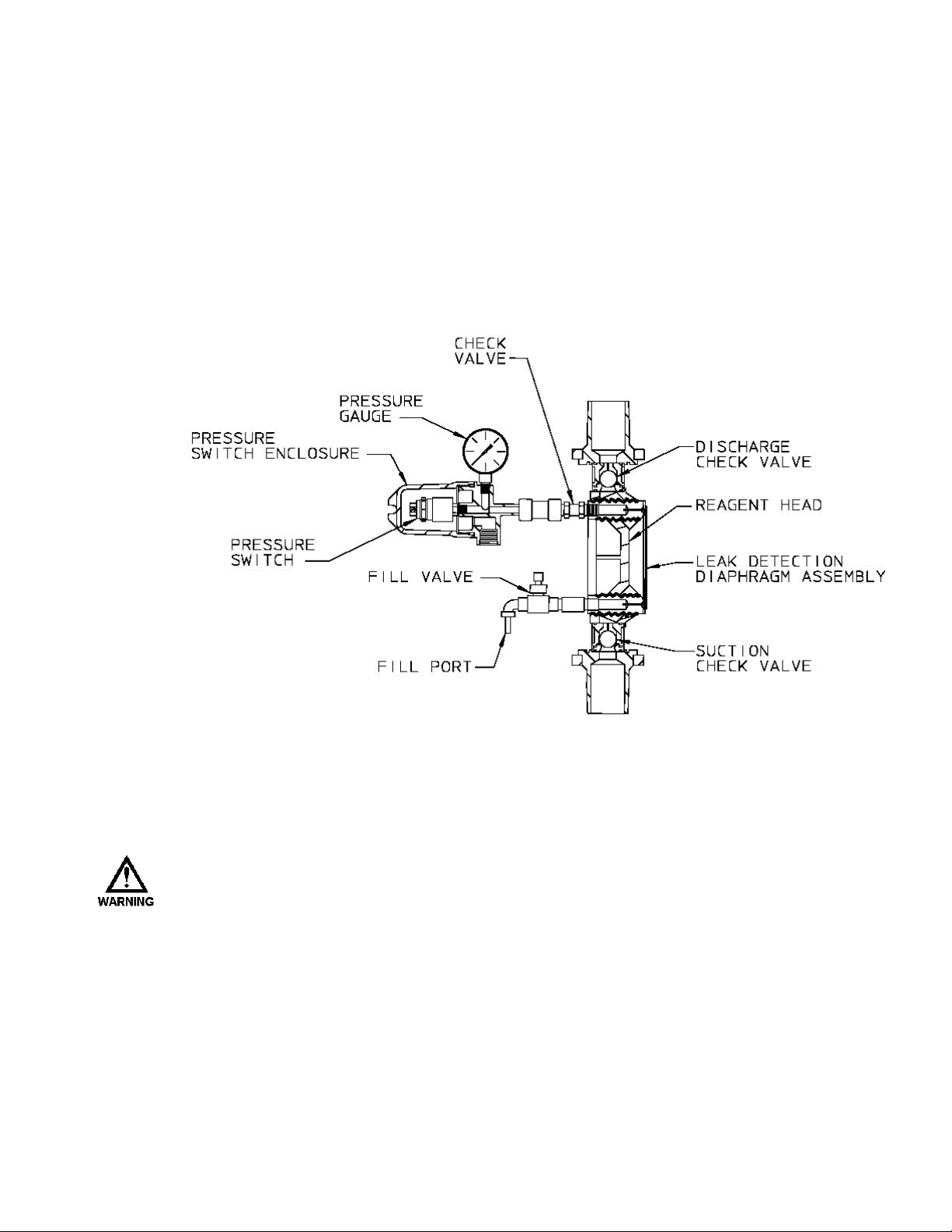
1.2 PULSAlarm Reagent Head
The PULSAlarm leak detection
reagent head assembly consists of
reagent head, leak detection
diaphragm, suction and discharge
check valves, bleed port, and optional
switch and gauge. The reagent head,
diaphragm, suction and discharge
check valves are the only parts of the
pump to contact the process liquid;
consequently, maintenance is critical
to pump performance
A
SEALED SYSTEM MUST BE MAINTAINED AT ALL TIMES DURING PUMP OPERATION,
WHETHER LEAK DETECTION IS REQUIRED OR NOT. IF THE PROPER LEVEL OF
VACUUM, BETWEEN 10 IN AND 26 IN.
PRESSURE SYSTEM IS NOT PRESENT, DECREASED FLOW AND/OR DIAPHRAGM
DAMAGE WILL OCCUR. PLEASE NOTE THAT THE FACTORY SETPOINT FOR
ACTUATION OF THE VACUUM SWITCH IS 6 IN
(
PRESSURE
).
(250
Figure 1 – reagent head
MM TO
650MM) HG,
(152MM) HG (
VACUUM) OR 5 PSIG
OR A SEALED
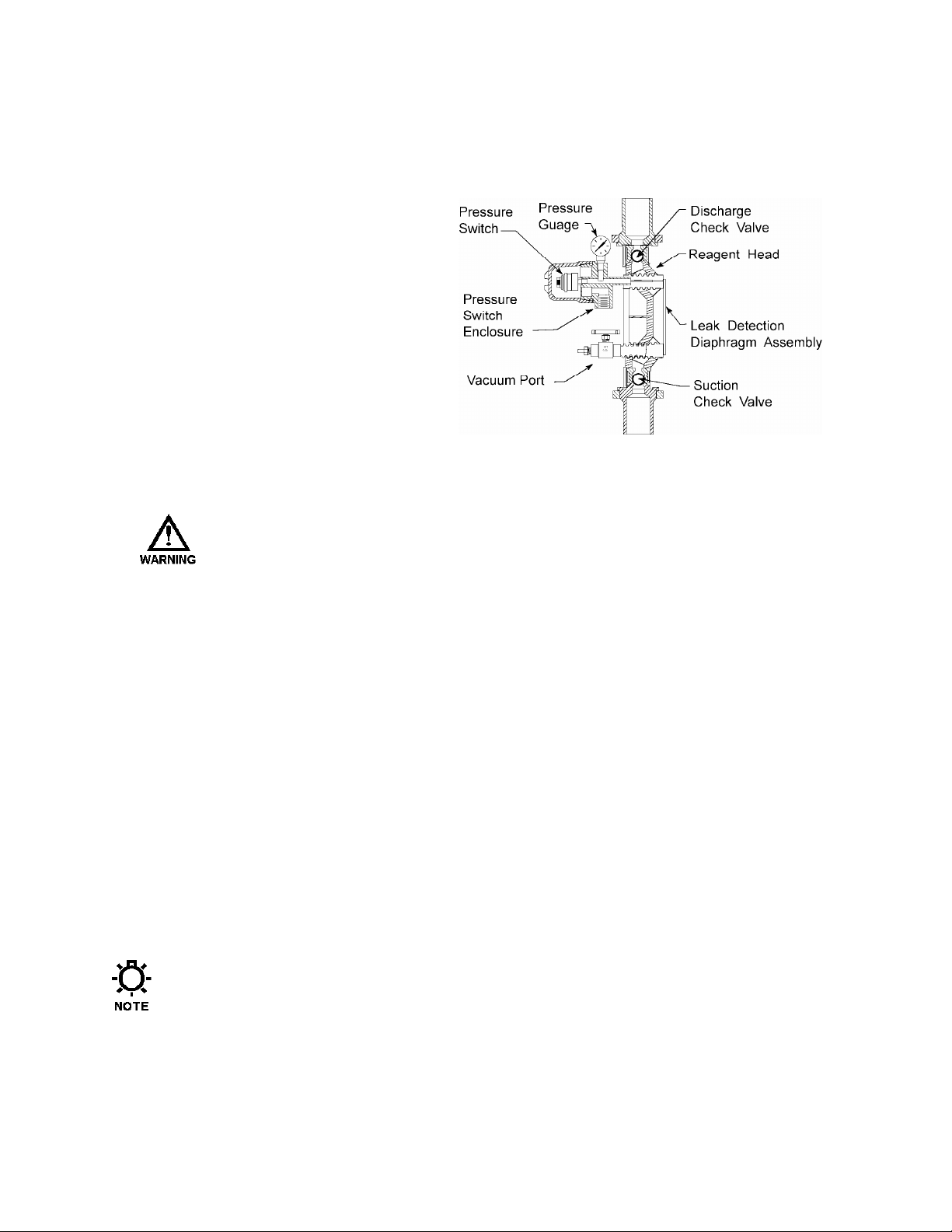
1.3 PULSAlarm Leak Detection Diaphragm
Double, or sandwiched, PTFE diaphragms are sealed at their peripheries to an intermediate metal spacer
ring. The space between the diaphragms is sealed so that the diaphragm functions as does a standard
single diaphragm. For the vacuum system, the space between the diaphragms is evacuated of air to
produce a vacuum. For the pressure system, the space between the diaphragms is filled with a small
amount of fluid. This space is connected to an adjustable electrical switch (optional) that actuates in
response to loss of vacuum or buildup of pressure resulting from rupture of either or both diaphragms.
Switch operation can be used to perform any external function, typically to signal an alarm or turn off the
pump. Refer to Figures 1 and 2.
During installation, ensure that adequate space is available at the front of the reagent head
assembly to allow for service of both the pressure switch and the diaphragm assembly.
6
Page 7
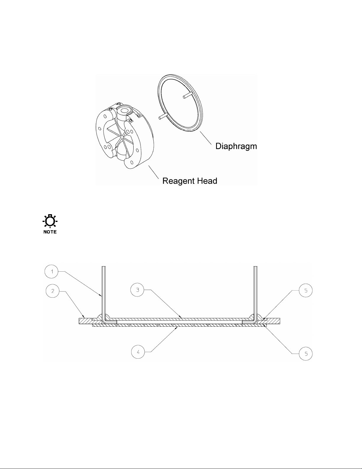
1.4 Diaphragm Construction
The adhesive rings aid in assembly and are not present for sealing purposes.
Capillary tube
Support ring
Process side PTFE layer
Hydraulic side PTFE layer
Figure 2 – diaphragm construction
Adhesive ring
Adhesive ring
7
Page 8
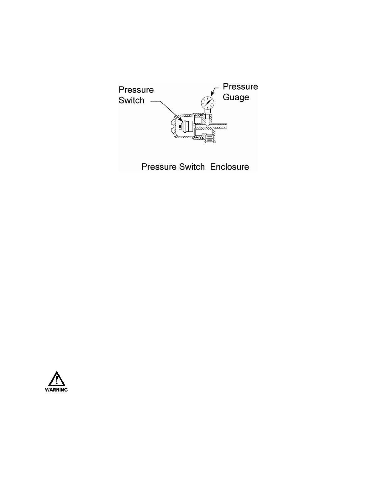
2. Electrical
If equipped with an optional pressure switch, install electrical wiring and conduit in accordance
with local electrical codes.
The switch is rated as follows:
Figure 3 – switch and housing
30 VDC or 125 VAC 1 Ampere Resistive.
The switch is the SPDT (single pole, double throw) type and can therefore be connected to
either open or to close upon detection of diaphragm leak condition. Contacts or wires are
identified as follows:
Normally Open (NO) wire color WHITE
Normally Closed (NC) wire color RED
Common (Com) wire color BLACK
T
HE ENCLOSURE IS LABELED WITH APPLICABLE SAFETY AGENCY RATINGS FOR
HAZARDOUS AREA INSTALLATION. SINCE THE SWITCH IS OF THE MECHANICAL
CONTACT TYPE, IT CAN NEVER QUALIFY AS NON-SPARKING (NON-INCENDIVE, OR
FOR OCCASIONAL AND SHORT-TERM HAZARDOUS AREA USE. PROTECTION MUST BE
PROVIDED BY THE ENCLOSURE.
“M”)
Page 9

3.
Setup for Vacuum system
A vacuum must be maintained at all times during
pump operation, otherwise, the diaphragm halves
may separate during the suction stroke of the
pump, reducing flow capacity and potentially
damaging the diaphragm.
Pumps incorporating the leak detection option are
shipped from the factory with the system
evacuated to the operating vacuum of 650 mm Hg
(26 in. Hg). Due to flexure of the PTFE
diaphragms during transit and storage, the initial
vacuum may not be present at startup. When this
occurs, re-evacuate the system to the operating
vacuum of 650 mm Hg (26 in. Hg).
In all cases, it is advisable to assume vacuum
needs to be renewed if the pump has been out of
service.
Figure 4 – vacuum system
To Apply Vacuum:
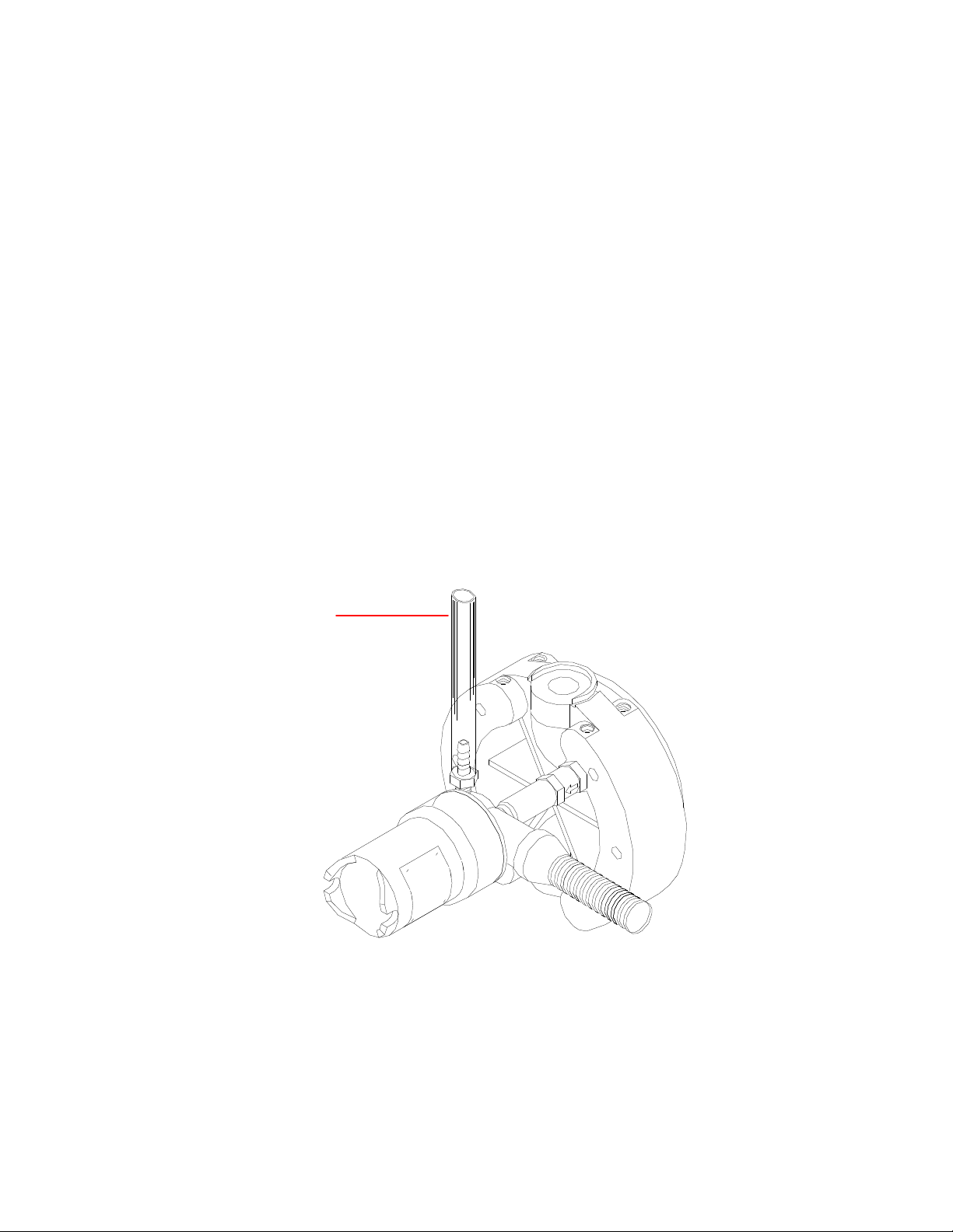
1. Connect a vacuum pump capable of generating 26 inches of vacuum to the vacuum port and
evacuate the system. A hand-operated vacuum pump is generally appropriate for this
procedure.
2. Open the needle valve on the vacuum port assembly.
3. Operate the vacuum pump to evacuate the system
4. Close the needle valve
5. Remove the vacuum pump.
6. If required, verify system operation and electrical connections.
9
Page 10
4. Setup for Pressure
Pumps incorporating pressure leak detection are shipped from the factory with the system fully
set up to work at full pump pressure. No further setup is required. The standard factory barrier
fluid is silicone oil, if any other customer-specified media is used it must be compatible with
construction materials. The system will require proper setup after maintenance or repairs, see
the following page for the proper procedure.
Figure 5 – pressure system
T
HE BARRIER FLUID USED TO PRIME THE SYSTEM WILL VARY WITH THE APPLICATION.
T
HE FLUID SELECTED MUST BE COMPATIBLE WITH THE MATERIALS OF CONSTRUCTION
USED IN THE DIAPHRAGM AND DETECTION ASSEMBLY. IT SHOULD ALSO BE COMPATIBLE
WITH THE PROCESS FLUID AND THE PROCESS CONDITIONS.
10
Page 11

To set up Pressure:
1. Complete re-assembly of the diaphragm, reagent head, and external components if they were
taken apart. Ensure that reagent head and tie-bar bolts are tightened according to the
appropriate torque specifications
2. Remove the pressure gauge from the housing body and replace it with a straight tubing
adaptor fitting. This will be referred to in this document as the “outlet side”
fitting
Figure 6 – fitting for priming “outlet side”
3. Remove the plug from the inlet side needle valve on the front of the reagent head, and install
a hose adaptor fitting. This will be referred to in this document as the “inlet side”.
Figure 7 – “inlet side”
11
Page 12
4. The method used to prime the system will vary with the chosen barrier fluid. The fluid must
be introduced under pressure on the inlet side. This pressure can be normal water pressure if
water is being used. It can be provided by a pressurized tank and/or a hand pump. Refer to
Section 4.1 for instructions on how to utilize a pressure chamber to achieve the fill. The fill
pressure should not exceed 30 psi (2 bar)
5. Connect a hand pump to the fitting on the outlet side of the system, and apply vacuum, which
serves to pull the barrier fluid through the system.
6. Attach the incoming barrier fluid supply under pressure to the inlet side and verify that the
needle valve is open.
7. WAIT…. The process will take time. Higher pressure will not help and may cause
damage to the diaphragm. Maintain pressure on the inlet side and vacuum on the outlet
side to move the fluid through the system.
8. Observe the fluid at the outlet (vacuum pump) side. When clear, air free fluid is observed,
close the inlet side needle valve and remove the pressure source.
9. Replace the plug into the needle valve to seal the system inlet.
10. Allow vacuum to remain on the outlet side of the system for approx. 2-3 minutes, this will aid
in the evacuation of excess fluid. Once complete, release the vacuum and remove the hand
pump.
11. Attach a short section of tubing to the fitting on the outlet side to catch excess fluid as the
system setup is completed in the next steps.
Open to
atmosphere
Figure 8 – bleed tubing
12. Ensure that the eccentric box of the pump has been filled to the appropriate level with the
correct hydraulic fluid.
13. If the pump is not already hydraulically primed, re-prime it now using the appropriate
procedure for a standard Pulsa Series flat diaphragm pump. If the diaphragm was never
removed, this step should not be necessary. If a new diaphragm is being installed, the pump
will need to be re-primed.
12
Page 13

14. In order to fully balance and evacuate the leak detection system, the pump must now run at
normal discharge pressure for a period of about 30 minutes to one hour. This ensures that
excess barrier fluid is fully evacuated from the system.
15. Supply either process fluid, or test fluid (i.e. water) to the suction fitting and ensure that the
discharge system is configured for safe operation. The pump can be started with minimal
discharge pressure and then slowly brought up to full pressure, if the system allows for this.
16. Apply power and start the pump.
17. Slowly increase the discharge pressure to full operating pressure, and continue to run the
pump.
18. During this time, excess barrier fluid will be displaced from the system into the length of
tubing attached to the outlet side, balancing the system for proper operation. A small pen
mark on the tube can assist in observing this process visually. Once the liquid in the tube no
longer rises, the evacuation should be complete.
19. After the startup period, remove the tubing and connection from the housing body and
reinstall the pressure gauge. Use thread sealing tape as required.
20. Verify the connections to the alarm switch if they were disturbed during maintenance.
21. The pump and pressure leak-detection system are now properly prepared and ready for
normal service. During normal operation, the gauge should indicate 0 (zero) pressure.
Under certain circumstances, the system may not completely evacuate excess
barrier fluid during the procedure as outlined above. In these cases, after several
days run time, a small amount of pressure may build in the system. If this occurs,
simply loosen the pressure gauge from the switch housing and relieve a small
amount of barrier fluid, returning the system to a zero-pressure state.
Once this startup procedure is completed, the pressure leak detection system
should require no further maintenance.
13
Page 14

4.1 Pressure fill chamber
Under certain conditions, when barrier fluids other than water are used, a pressure chamber can
be fabricated from readily available fittings that allows the barrier fluid to be fed under pressure
to the inlet of the system. Users may wish to fabricate a device based upon this sketch which will
aid in the setup of the pressure-based system.
Pressure inlet
Upper valve
Fluid chamber
Lower valve
Fluid outlet, to
reagent head
Figure 9 – optional fill chamber
14
Page 15

1. Connect a vacuum pump to the top fitting of the fluid fill device. Open BOTH valves
on the device.
2. Place the lower fill tube into the container of the barrier fluid
3. Using the vacuum function, use the hand pump to draw several ounces of fluid up into
the fill device.
4. Close both valves on the fill device
5. Remove the hose and fitting from the container, and connect the fluid fill device to the
inlet fitting on the pump head (the fitting with the needle valve).
6. Open the fill valve (needle valve) on the pump, and then open the two plastic valves on
the fluid fill device.
7. Switch the hand pump to the pressure function, and apply approximately 10-20 psi of
pressure to the fluid in the chamber. Once pressure is achieved, close the TOP valve
and disconnect the hand pump. There is now pressure pushing the barrier fluid into the
leak detection system.
8. Move the hand pump to the outlet side of the system, switch it to the vacuum function,
and continue with the filling process as outlined in the main document.
15
Page 16

5. Maintenance
Although the PULSAlarm leak detection system requires minimal maintenance,
vacuum must be maintained to prevent false alarms and diaphragm damage.
5.1 Switch Setpoint Adjustment
If the optional switch is purchased, it is factory preset at the specified vacuum setpoint, 150 mm
Hg (6 in. Hg), at which loss of vacuum causes the vacuum switch to actuate. The standard
pressure switch is set to actuate at 5 psig.
Use the following procedure to perform a Vacuum setpoint adjustment:
1. Disconnect the alarm circuit from the vacuum switch.
2. Remove the switch enclosure cover and loosen the knurled locking ring on the switch.
3. Rotate the hex adjusting ring counterclockwise to increase or clockwise to decrease the
setpoint.
4. Verify the new setpoint (refer to the next section).
5. Repeat steps (3) and (4) above until the required setpoint as attained.
6. Tighten the switch locking ring and replace the switch enclosure cover.
7. Reconnect the alarm circuit to the vacuum switch.
Use the following procedure to perform a setpoint adjustment test
8. Evacuate the system to approximately 650 mm Hg (26 in. Hg) OR properly prime and
prepare the pressure system.
9. Remove the switch cover and connect ohmmeter leads across the common terminal and the
other terminal used in operation (NO or NC).
10. Record the status of the switch (open or closed).
11. a. Vacuum: Break the vacuum system at any point external to the pump to permit gradual loss
of vacuum.
b. Pressure: remove the pressure gauge, and install a hand pump or other means of producing
a small amount of pressure in the system.
12. Observe the ohmmeter to detect actuation.
The setpoint can be observed by reading the vacuum/pressure
gauge upon actuation.
16
Page 17

5.2 PULSAlarm Diaphragm Maintenance
After diaphragm failure, pressurized process fluid can be present
in any part of the PULSAlarm leak detection vacuum system. Take
appropriate precautions and handle with care.
Figure 10 – diaphragm and head orientation
5.2.1 PULSAlarm Diaphragm Removal
Use the following procedure to remove the Leak Detection Diaphragm:
1. Disconnect the power source to the drive motor.
2. Relieve all pressure from the piping system, and close the inlet and outlet shutoff valves
3. Take all precautions to prevent environmental and personnel exposure to hazardous materials.
4. Place a suitable container underneath the pump head to catch any liquid leakage.
5. Disconnect process piping and drain any process liquid, following material safety
precautions.
6. Remove all but one top reagent head bolt. Oil will leak out between the pump head and
reagent head as the bolts are loosened.
7. Tilt the head and pour out any liquids retained by the check valves into a suitable container,
continuing to follow safety precautions as appropriate.
8. Remove the alarm switch assembly or pressure gauge from the reagent head.
9. Remove the bleed valve assembly and flat gasket from the reagent head.
10. Rinse or clean the reagent head with an appropriate material.
11. Remove the diaphragm by running a blunt blade along the periphery and prying it out.
17
Page 18

5.2.2 Inspection
Remove and inspect the diaphragm assembly. It may have taken a permanent convex/concave set
as a result of normal flexure and conformance to the dish-plate. This condition is normal and is
not cause for replacement. The diaphragm must be replaced if it is deformed, dimpled, or
obviously damaged.
If the diaphragms have been removed from the spacer ring, the entire assembly
should be replaced to ensure proper sealing of its components.
5.2.3 PULSAlarm Diaphragm Reinstallation
1. Ensure that the critical sealing areas of diaphragm assembly, reagent head, and pump head
are clean and free from debris. Align the diaphragm assembly capillary tubes with mating
holes in the seal groove in the reagent head and position it in place against the reagent head.
Ensure seating of the diaphragm sealing ring into the mating groove in the reagent head.
2. Install the reagent head bolts and tighten in an alternating pattern to ensure an even seating
force. Torque to the values recommended in the Installation, Operation, and Maintenance
manual appropriate to the pump.
3. Apply sealing compound to the gauge/pressure switch assembly and reinstall to the upper
port on the reagent head.
4. Apply sealing compound to the fill valve assembly and reinstall to the lower port on the
reagent head.
5. Open the needle valve
6. Connect a hand-held vacuum pump or other vacuum source to the vacuum port, which fits 6
mm (1/4 in.) I.D. tubing.
7. For a vacuum system, evacuate to approximately 650 mm Hg (26 in. Hg) and securely
tighten the needle valve after evacuation. Diaphragm damage or decreased flow will occur
if a vacuum is not drawn before the pump is returned to service. Refer to Section 3 “Setup
for Vacuum”.
8. For a pressure system, see Section 4, “Setup for Pressure”
9. Re-prime the pump head hydraulic system
10. If required, test vacuum or pressure system operation.
11. After diaphragm set-up and priming, the pump is ready to be returned to service.
18
Page 19

5.3 Leak Detection system conversion
Leak detection system conversion information can be found in Bulletin CV-LD-0203 (vacuum to
pressure system). For further conversion information and kits, please contact your local
Pulsafeeder sales representative.
6. Silicone Fluid MSDS
The following safety information is provided for the silicone fluid used as standard in the
PULSAlarm pressure-based leak detection system. Your system may or may not use this fluid,
consult your pump Specification Sheet or facility management for guidance.
DOW CORNING CORPORATION Material Safety Data Sheet
DOW CORNING 200(R) FLUID, 5 CST.
1. IDENTIFICATION OF THE SUBSTANCE AND OF THE COMPANY
Dow Corning Corporation South Saginaw Road Midland, Michigan 48686
24 Hour Emergency Telephone: (517) 496-5900
Customer Service: (517) 496-6000
Product Disposal Information: (517) 496-6315
CHEMTREC: (800) 424-9300
MSDS No.: 01013131 Revision Date: 2000/10/02
Generic Description: Silicone
Physical Form: Liquid
Color: Colorless
Odor: Odorless
NFPA Profile: Health 0 Flammability 1 Instability/Reactivity 0
Note: NFPA = National Fire Protection Association
2. OSHA HAZARDOUS COMPONENTS
None present. This is not a hazardous material as defined in the OSHA Hazard Communication
Standard.
3. EFFECTS OF OVEREXPOSURE
Acute Effects
Eye: Direct contact may cause temporary redness and discomfort.
Skin: No significant irritation expected from a single short-term exposure.
Inhalation: No significant effects expected from a single short-term exposure.
Oral: Low ingestion hazard in normal use.
Prolonged/Repeated Exposure Effects
Skin: No known applicable information.
Inhalation: No known applicable information.
Oral: No known applicable information.
Signs and Symptoms of Overexposure
No known applicable information.
19
Page 20

Medical Conditions Aggravated by Exposure
No known applicable information.
The above listed potential effects of overexposure are based on actual data, results of studies performed upon similar
compositions, component data and/or expert review of the product. Please refer to Section 11 for the detailed
toxicology
information.
4. FIRST AID MEASURES
Eye: Immediately flush with water.
Skin: No first aid should be needed.
Inhalation: No first aid should be needed.
Oral: No first aid should be needed.
Comments: Treat symptomatically.
5. FIRE FIGHTING MEASURES
Flash Point: > 214 °F / > 101.1 °C (Closed Cup)
Autoignition Temperature: Not determined.
Flammability Limits in Air: Not determined.
Extinguishing Media: On large fires use dry chemical, foam or water spray. On small fires use carbon
dioxide (CO2), dry chemical or water spray. Water can be used to cool fire exposed containers.
Fire Fighting Measures: Self-contained breathing apparatus and protective clothing should be worn in
fighting large fires involving chemicals. Determine the need to evacuate or isolate the area according to
your local emergency plan. Use water spray to keep fire exposed
containers cool.
Unusual Fire Hazards: None.
Hazardous Decomposition Products Thermal breakdown of this product during fire or very high heat
conditions may evolve the following hazardous
decomposition products: Carbon oxides and traces of incompletely burned carbon compounds. Silicon
dioxide. Formaldehyde.
6. ACCIDENTAL RELEASE MEASURES
Containment/Clean up: Determine whether to evacuate or isolate the area according to your local
emergency plan. Observe all personal protection equipment recommendations described in
Sections 5 and 8. For large spills, provide diking or other appropriate containment to
keep material from spreading. If diked material can be pumped, store recovered
material in appropriate container. Clean up remaining materials from spill with suitable
absorbant. Clean area as appropriate since some silicone materials, even in small
quantities, may present a slip hazard. Final cleaning may require use of steam,
solvents or detergents. Dispose of saturated absorbant or cleaning materials
appropriately, since spontaneous heating may occur. Local, state and federal laws and
regulations may apply to releases and disposal of this material, as well as those
materials and items employed in the cleanup of releases. You will need to determine
which federal, state and local laws and regulations are applicable. Sections 13 and 15
of this MSDS provide information regarding certain federal and state requirements.
Note: See section 8 for Personal Protective Equipment for Spills. Call Dow Corning Corporation, (517)
496-5900, if additional information is required.
7. HANDLING AND STORAGE
Use with adequate ventilation. Avoid eye contact.
Use reasonable care and store away from oxidizing materials.
8. EXPOSURE CONTROLS / PERSONAL PROTECTION
20
Page 21

Component Exposure Limits
There are no components with workplace exposure limits.
Engineering Controls
Local Ventilation: None should be needed.
General Ventilation: Recommended.
Personal Protective Equipment for Routine Handling
Eyes: Use proper protection - safety glasses as a minimum.
Skin: Washing at mealtime and end of shift is adequate.
Suitable Gloves: No special protection needed.
Inhalation: No respiratory protection should be needed.
Suitable Respirator: None should be needed.
Personal Protective Equipment for Spills
Eyes: Use proper protection - safety glasses as a minimum.
Skin: Washing at mealtime and end of shift is adequate.
Inhalation/Suitable Respirator: No respiratory protection should be needed.
Precautionary Measures: Avoid eye contact. Use reasonable care.
Comments: When heated to temperatures above 150 degrees C in the presence of air, product can form
formaldehyde vapors. Formaldehyde is a potential cancer hazard, a known skin
and respiratory sensitizer, and an irritant to the eyes, nose, throat, skin, and digestive
system. Safe handling conditions may be maintained by keeping vapor concentrations
within the OSHA Permissible Exposure Limit for formaldehyde.
Note: These precautions are for room temperature handling. Use at elevated temperature or aerosol/spray
applications may require added precautions.
9. PHYSICAL AND CHEMICAL PROPERTIES
Physical Form: Liquid
Color: Colorless
Odor: Odorless
Specific Gravity @ 25°C: 0.915
Viscosity: 5 cSt
Freezing/Melting Point: Not determined.
Boiling Point: > 35C/95F
Vapor Pressure @ 25°C: Not determined.
Vapor Density: Not determined.
Solubility in Water: Not determined.
pH: Not determined.
Volatile Content: Not determined.
Note: The above information is not intended for use in preparing product specifications. Contact Dow Corning before
writing specifications.
10. STABILITY AND REACTIVITY
Chemical Stability: Stable.
Hazardous Polymerization: Hazardous polymerization will not occur.
Conditions to Avoid: None.
Materials to Avoid: Oxidizing material can cause a reaction.
11. TOXICOLOGICAL INFORMATION
Acute Toxicology Data for Product Complete information is not yet available.
Component Toxicology Information
Special Hazard Information on Components
12. ECOLOGICAL INFORMATION
Environmental Fate and Distribution
Air: This product is a high molecular weight liquid polymer which has a very low vapour
pressure (<1 mm Hg). As a result it is unlikely to become an atmospheric contaminant
21
Page 22

unless generated as an aerosol.
Water: This product has a very low water solubility (< 100 ppb). As it has a specific gravity of
< 1, if discharged to water, it will initially form a surface film. As the product is non
volatile and has a high binding affinity for particulate matter, it will adsorb to
particulates and sediment out.
Soil: If discharged to surface water, this product will bind to sediment. If discharged in
effluent to a waste water treatment plant, the product is removed from the aqueous
phase by binding to sewage sludge. If the sewage sludge is subsequently spread on
soil, the silicone product is expected to degrade.
Degradation: This product, polydimethylsiloxane, degrades in soil abiotically to form smaller
molecules. These in turn are either biodegraded in soil or volatilized into the air where
they are broken down in the presence of sunlight. Under appropriate conditions, the
ultimate degradation products are inorganic silica, carbon dioxide and water vapour.
Due to the very low water solubility of this product, standard OECD protocols for ready
and inherent biodegradability are not suitable for measuring the biodegradability of this
product. The product is removed >80% during the sewage treatment process.
Environmental Effects
Toxicity to Water Organisms: Based on analogy to similar materials this product is expected to exhibit
low toxicity to aquatic organisms.
Toxicity to Soil Organisms: Experiments show that when sewage sludge containing polydimethylsiloxane
is added to soil, it has no effect on soil micro-organisms, earthworms or subsequent crops grown in the
soil.
Bioaccumulation: This product is a liquid and is a high molecular weight polymer. Due to its physical size
it is unable to pass through, or be absorbed by biological membranes. This has been confirmed by testing
or analogy with similar products.
Fate and Effects in Waste Water Treatment Plants
This product or similar products has been shown to be non-toxic to sewage sludge bacteria.
Ecotoxicity Classification Criteria
Hazard Parameters (LC50 or EC50) High Medium Low
Acute Aquatic Toxicity (mg/L) <=1 >1 and <=100 >100
Acute Terrestrial Toxicity <=100 >100 and <= 2000 >2000
This table is adapted from "Environmental Toxicology and Risk Assessment", ASTM STP 1179, p.34, 1993.
This table can be used to classify the ecotoxicity of this product when ecotoxicity data is listed above. Please read the other
information presented in the section concerning the overall ecological safety of this material.
13. DISPOSAL CONSIDERATIONS
RCRA Hazard Class (40 CFR 261)
When a decision is made to discard this material, as received, is it classified as a hazardous waste? No
State or local laws may impose additional regulatory requirements regarding disposal.
Call Dow Corning Corporate Environmental Management, (517) 496-6315, if additional information is
required.
14. TRANSPORT INFORMATION
DOT Road Shipment Information (49 CFR 172.101) Not subject to DOT.
Ocean Shipment (IMDG) Not subject to IMDG code.
Air Shipment (ICAO) Not subject to ICAO regulations.
Call Dow Corning Transporation, (517) 496-8577, if additional information is required.
15. REGULATORY INFORMATION
Contents of this MSDS comply with the OSHA Hazard Communication Standard 29 CFR 1910.1200.
TSCA Status: All chemical substances in this material are included on or exempted from listing on the
TSCA Inventory of Chemical Substances.
EPA SARA Title III Chemical Listings
Section 302 Extremely Hazardous Substances: None.
22
Page 23

Section 304 CERCLA Hazardous Substances: None.
Section 312 Hazard Class:
Acute: No
Chronic: No
Fire: No
Pressure: No
Reactive: No
Section 313 Toxic Chemicals: None present or none present in regulated quantities.
Supplemental State Compliance Information California
Warning: This product contains the following chemical(s) listed by the State of California under the Safe
Drinking Water and Toxic Enforcement Act of 1986 (Proposition 65) as being known to cause cancer,
birth defects or other reproductive harm.
Massachusetts No ingredient regulated by MA Right-to-Know Law present.
New Jersey CAS Number Wt % Component Name 63148-62-9 > 60.0 Polydimethylsiloxane
Pennsylvania CAS Number Wt % Component Name 63148-62-9 > 60.0 Polydimethylsiloxane
16. OTHER INFORMATION
Prepared by: Dow Corning Corporation
These data are offered in good faith as typical values and not as product specifications. No warranty,
either expressed or implied, is hereby made. The recommended industrial hygiene and safe handling
procedures are believed to be generally applicable. However, each user should review these
recommendations in the specific context of the intended use and determine whether they are appropriate.
(R) indicates Registered Trademark
23
Page 24

IOM–PSVLD-03
Rev B
En g i n e e r e d P u m p O p e ra ti o n s PUL S A l a r m f o r Pu ls a Se ri es
28 8 3 B r i g ht on -H e n ri e t t a T o w n li ne R oa d
Ro c h e s t e r , N Y 1 4 6 2 3
Te l e p h o ne ( 58 5) 2 9 2 - 8 0 0 0 F a x ( 5 8 5 ) 4 2 4 - 5 6 19
ht t p : / / w w w. pu ls a. c o m p u ls a@ i d e x c o r p . c o m
24
 Loading...