

Page 1

Regenerative Turbine Pump
Installation
Operation
Maintenance
Instruction
Bulletin #: IOM – RGT0700 - Rev. C
Manufacturers of Quality Pumps,
Controls and Systems
Engineered Pump Operations
2883 Brighton-Henrietta Townline Road
Rochester, New York 14623
Telephone: (585) 292-8000 Fax: (585) 424-5619
http://www.pulsa.com pulsa@idexcorp.com
Page 2

ISOCHEM RGT FACTORY SERVICE POLICY
If you are experiencing a problem with your Isochem pump, first review the troubleshooting guide. If
the problem is not covered or cannot be solved, please contact your local authorized Sales
Representative or our Technical Service Department at (585) 292-8000 for further assistance.
Trained individuals are available to diagnose your problem and arrange a solution. Solutions may
include purchasing a replacement unit or returning the pump to the factory for inspection and repair.
All returns require a Return Material Authorization (RMA) number to be issued by Pulsafeeder.
Replacements purchased under a possible warranty situation may be credited after an examination of
the original equipment by Pulsafeeder personnel.
All components may be purchased for field replacement. Refer to the appropriate IOM section for
more information and part numbers. Parts purchased to correct a warranty issue may be credited after
examination of the original parts by Pulsafeeder personnel. Parts returned for warranty consideration
that test satisfactorily, will be sent back to the originator via freight collect.
Any field modifications will void the Pulsafeeder warranty. Out-of-warranty repairs will be
subject to Pulsafeeder's standard bench fees and testing costs associated with replacement
components.
Copyright
Copyright © 2005 Pulsafeeder, Inc. All rights reserved.
Information in this document is subject to change without notice. No part of this publication may be
reproduced, stored in a retrieval system or transmitted in any form or any means electronic or mechanical,
including photocopying and recording for any purpose other than the purchaser’s personal use without the
written permission of Pulsafeeder.
ii
Page 3

iii
Table of Contents
1. INTRODUCTION.....................................................................................................................................1
2. SAFETY CONSIDERATIONS ....................................................................................................................3
3. EQUIPMENT INSPECTION.......................................................................................................................3
4. INSTALLATION REQUIREMENTS .............................................................................................................4
5. STARTUP AND OPERATION.................................................................................................................... 7
6. MAINTENANCE .....................................................................................................................................8
6.1 Maintenance Precautions....................................................................................................... 8
6.2 Disassembling the No. 10 Pump ...........................................................................................9
6.3 Disassembling the No. 12 Pump ...........................................................................................11
6.4 Inspection................................................................................................................................ 13
6.4.1 Flow Channel Inspection................................................................................................13
6.4.2 Wear Plate Inspection.....................................................................................................14
6.4.3 Shaft Bearing Inspection................................................................................................14
6.4.4 Choke Point Inspection .................................................................................................. 14
6.5 Parts Replacement.................................................................................................................. 15
6.5.1 Wear Plates ...................................................................................................................... 15
6.5.2 Bearings........................................................................................................................... 15
6.5.3 Reassembling the No. 10 Pump.....................................................................................16
6.5.4 Reassembling the No. 12 Pump ..................................................................................... 20
7. TROUBLESHOOTING GUIDE................................................................................................................... 24
APPENDIX A – SPECIFICATIONS ..................................................................................................................25
APPENDIX B – BOLT PATTERN....................................................................................................................25
APPENDIX C – EXPLODED DRAWING ...........................................................................................................26
APPENDIX D – OPTIONS..............................................................................................................................29
APPENDIX E – BILL OF MATERIALS .............................................................................................................30
APPENDIX F – POWER FRAME ASSEMBLY................................................................................................... 34
Power Frame Maintenance.................................................................................................................35
APPENDIX G – PERFORMANCE CURVES ...................................................................................................... 36
Page 4

iv
Page 5
Co
nventions
For the remainder of this bulletin, the following Conventions are in effect.
A WARNING DEFINES A CONDITION THAT COULD CAUSE DAMAGE TO BOTH
THE EQUIPMENT AND THE PERSONNEL OPERATING IT. PAY CLOSE
ATTENTION TO ANY WARNING.
Notes are general information meant to make operating the equipment easier.
Change History
Rev # Date Author Section Nature of Change
A 5/22/00
B
C 6-30-2005 BMJ
7/26/00 RM 5.0 Updated Disassembly & Reassembly Procedures.
7/26/00 CA
RM Appendix E Updated Performance Curves.
CA Appendix D Updated Bill of Materials.
Appendix B Updated Exploded Drawings.
Appendix D Updated Bill of Materials.
Appendix E Updated Performance Curves.
Misc Verbiage updates
Section 2 Added safety information
Section 6 Updated reassembly instructions specific to shimming of
front cover for proper clearances
v
Page 6
1. Introduction
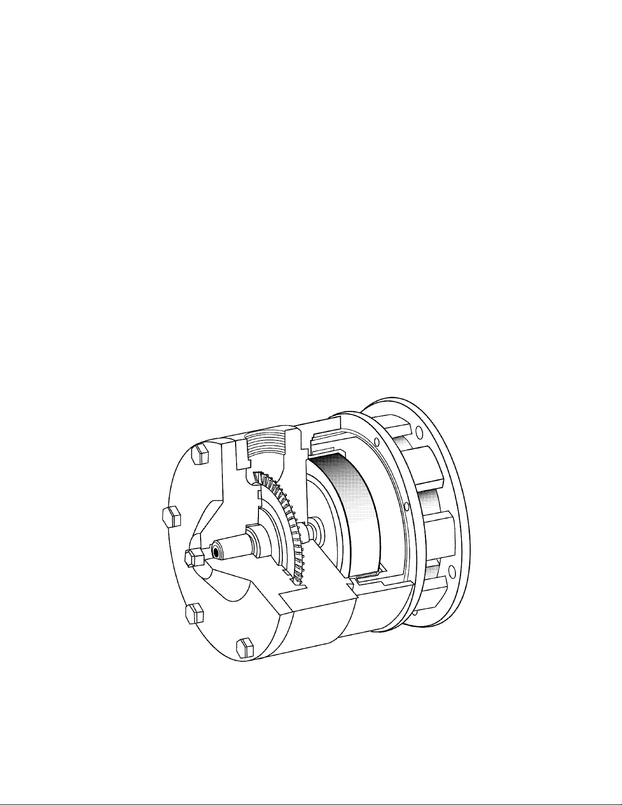
The Isochem® Regenerative Turbine pump (RGT) is uniquely different from the more familiar
types of pumps. As the pumped liquid progresses from suction to discharge, it is continuously
circulated between the impeller vanes and the walls of the flow passage in a helical path, the axis
of which coincides with the flow passage. This process results in a significantly higher buildup
of pressure than that which occurs in the similar but simpler centrifugal pump.
Figure 1
The turbine pump is in many ways an intermediate between the centrifugal and positive
displacement types. As discharge pressure increases, flow decreases and the power required to
drive the pump increases.
Flow is directly controlled by discharge pressure: the greater the pressure, the lower the flow
rate. This can be most readily achieved by throttling the discharge; however care must be taken
to not exceed the power level of the motor. Flow can be regulated using a variable bypass
system, allowing operation at reduced pressure and power draw by dumping excess flow, usually
back to a supply tank.
A very small clearance is maintained between the impeller, wear plates, and other internal
surfaces. Since the impeller floats freely in the axial direction relative to the pump, a film of fluid
is present on either side of the impeller so that there is no contact and negligible wear between
impeller and wear plates.
Isochem RGT pumps use magnetic coupled, sealless technology, which eliminates the need for a
rotary mechanical seal and enables the pump to handle hazardous fluids safely with zero leakage.
1
Page 7
Standard Isochem RGT pumps are close-coupled (motor mounted directly to the rear of the
pump) which provides greater assembled strength, enclosure of moving parts, and compact
design. An optional power frame unit is available if required for motor compatibility (see
Appendix G).
All Isochem pumps transmit rotation from the motor shaft to the impeller shaft by means of a
magnetic drive coupling. An encapsulated driven magnet assembly is installed on the end of the
impeller shaft. It is surrounded by a containment can, which constitutes the rearmost part of the
pump enclosure. A drive magnet installed on the motor shaft rotates around the containment can.
Drive torque is transferred through the containment can by magnetic attraction between the drive
and driven magnet assemblies, causing the pump shaft to rotate. The containment can acts as a
fluid barrier, eliminating the need for a dynamic seal.
The magnetic coupling has an inherent characteristic that causes it to “decouple” if the coupling
torque limit is exceeded. This could happen if a piece of foreign material were to jam the pump
impeller or if unusually high torque was developed for any reason.
The magnets can operate decoupled for short periods of time without losing their magnetic
strength provided that temperature does not exceed specified limits (refer to Appendix A – Pump
Specifications).
The Isochem RGT pump is available in several different materials, and care should be taken that
all pump components (housing, wearplates, bearings) are compatible with the process liquid.
Consult with the factory for applications involving a specific gravity or viscosity greater than that
of water.
2
Page 8

2. Safety Considerations
• Read and understand all related instructions and documentation before attempting to install
or maintain this equipment
• Keep this and all documents (specification sheets, shipment records, maintenance records)
in a safe place which is accessible to those who operate or maintain this equipment.
• Observe all special instructions, notes, and cautions.
• Act with care and exercise good common sense and judgment during all installation,
adjustment, and maintenance procedures.
• Ensure that all safety rules, work procedures, and standards that are applicable to your
company and facility are followed during the installation, maintenance, and operation of
this equipment.
• Use for any application other than as described within this documentation is considered
unsafe and voids all certification markings and warranties.
• Always ensure that all factory supplied guards and covers are in place before operating this
equipment.
• The Isochem series of pumps relies on strong magnets to transfer power from the drive to
the pump system. Users are cautioned to keep magnetically sensitive items such as
watches, credit cards and ID badges, and medical equipment away from the pump and drive
mechanisms.
• See additional maintenance precautions listed in Section 6.
3. Equipment Inspection
Check all equipment for completeness against the order and for any evidence of shipping damage.
Shortages or damage must be reported immediately to the carrier and to your Isochem supplier.
If immediate installation is not scheduled, the following steps should be taken:
1. Leave pump in the original shipping carton.
2. Store indoors in a dry environment. Avoid temperature variations.
3. Leave all shipping plugs in place.
4. Contact the motor manufacturer for specific motor storage information.
Occasionally during shipment, storage, or installation. misalignment or other damage can occur.
For this reason it is recommended that each unit be tested with water in some convenient area
prior to piping into the actual process system.
3
Page 9
4. Installation Requirements
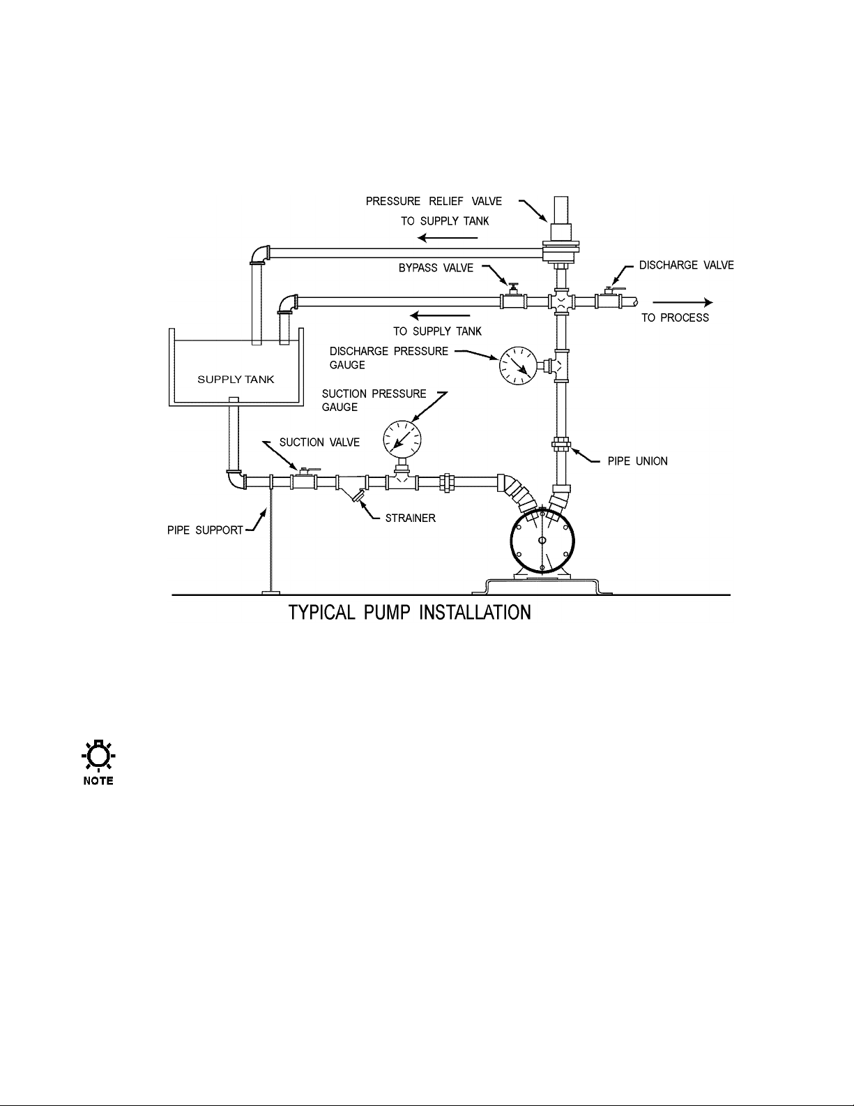
The pump installation site should provide easy access for routine maintenance and when possible
to protect the pump from the elements and from leaks or drips from nearby process equipment.
Figure 2
IN A POWER FRAME (THAT IS, NOT CLOSE-COUPLED) INSTALLATION, THE USE OF A LOW-
BACKLASH OR RELATIVELY RIGID MOTOR COUPLING IS RECOMMENDED TO PREVENT MAGNETIC
DE-COUPLING AT STARTUP OR UNDER WIDELY VARYING PROCESS CONDITIONS.
THE PROVISION OF A “SOFT-START” MOTOR STARTER WILL REDUCE THE POSSIBILITY OF
MAGNETIC DE-COUPLING AT STARTUP WITH A FAST-STARTING OR OVERSIZED MOTOR.
AS THE PUMP IS SUPPORTED BY THE MOTOR MOUNT, TAKE CARE THAT THE SUCTION AND
DISCHARGE PIPING DOES NOT APPLY FORCES OR MOMENTS (TWISTING) TO THE PUMP.
FOR OPTIMUM PERFORMANCE, A MINIMUM 1-1/2 INCH SUCTION LINE SIZE IS RECOMMENDED
4
Page 10
1. Bolt the pump down firmly to the mounting surface. Provide for air movement over the electric
DISCHARGE PORT
DISCHARGE PORT
SUCTION PORT
SUCTION PORT
motor as required.
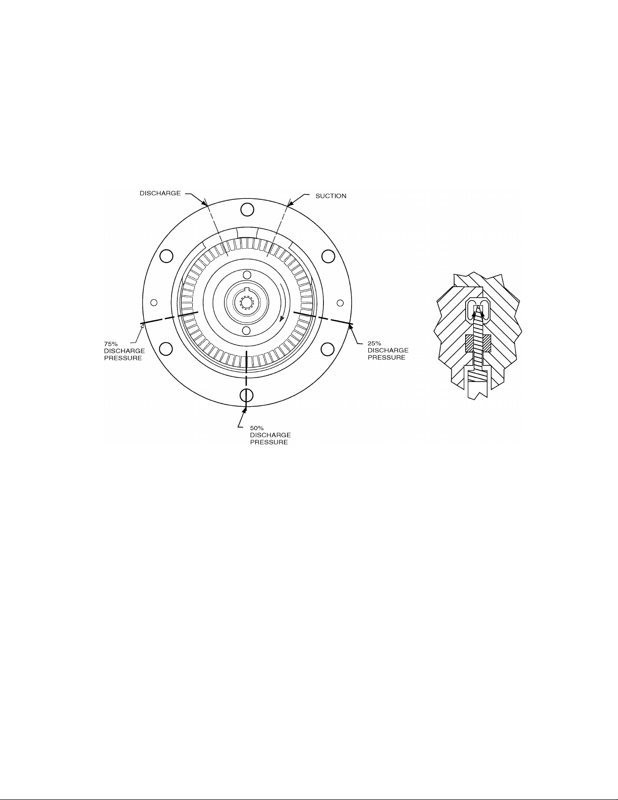
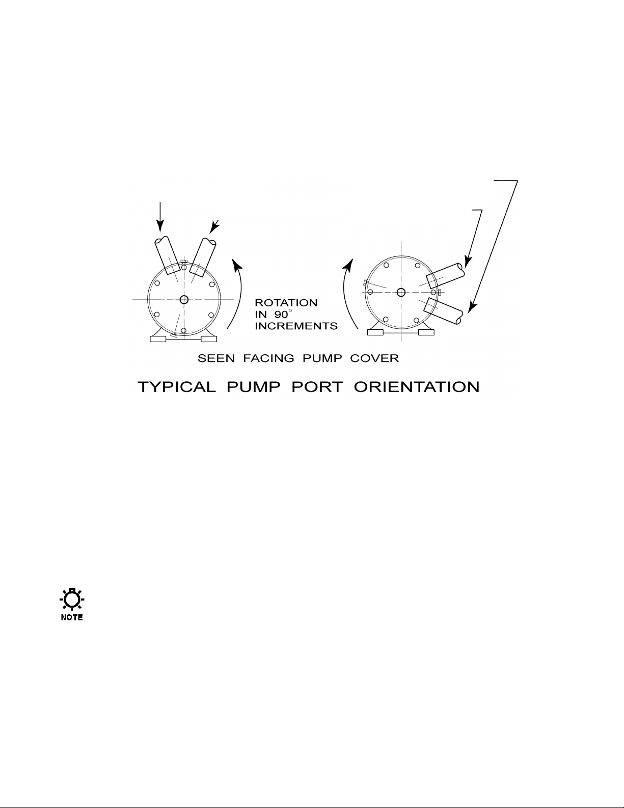
The pump is functionally symmetrical so that the suction and discharge ports can be reversed
(with direction of rotation) and the housing (with cover) can be rotated to suit the installation if
required. Refer to Figure 3, for typical installation and the required relation between rotation and
direction of flow.
Figure 3
2. It is recommended to install vacuum/pressure gauges in the suction and discharge lines to monitor
system operation.
3. Keep suction lines short and straight to minimize friction loss to the pump. Make sure that the
pump will not starve or run dry. Flooded suction or gravity feed of fluid to the pump inlet is
preferred and eliminates manual priming.
4. Use only full-bore ball valves or gate valves in the suction piping. If suction strainers are used,
size them to minimize pressure drop and select a type that is easily cleaned. Strainers should be
regularly inspected and cleared of debris as required during operation.
THE ISOCHEM RGT PUMP SHOULD BE USED TO PUMP CLEAN, CLEAR LIQUIDS ONLY. THIS PUMP
CANNOT HANDLE SOLIDS OR PARTICULATES IN THE PROCESS STREAM.
5. Arrange all suction piping and fittings to prevent formation of air pockets. Make sure all joints
are air tight.
6. Flush all suction lines prior to mating up to the pump. Use unions or other appropriate fittings for
ease of maintenance.
5
Page 11

7. Do not spring piping, either suction or discharge, when mating up to the pump. Use supports or
hangers at intervals as required. When necessary, provide for thermal expansion and contraction
so that no strain is placed upon the pump.
8. Check all bolts and nuts for tightness. Correct any conditions that could cause destructive
vibration or leakage.
9. When required, provide a proper system for containment can flush and/or drain.
10. If start-up screens are used, be sure they do not clog and starve the suction system. Start-up
screens should be removed prior to placing the system into regular operation.
11. If a flexible suction line is used, select the materials and install them so that they do not collapse
(causing a starved condition).
12. When taking suction from a tank or vessel, avoid entry of sludge, solids, etc. into the suction line
by placing the suction line inlet above maximum level of solids.
13. When a bypass system is used to control flow from the pump, the bypassed fluid should be piped
back to the suction vessel to prevent heat build-up due to recirculation. If it is absolutely
necessary to pipe bypass back to the pump suction line, the point of entry should be at least 10
pipe diameters away from the suction inlet. Provision for cooling should be made in the event of
excessive heat buildup caused by fluid recirculation.
14. Where pumped fluids may solidify, crystallize, precipitate etc., provision should be made to
thoroughly flush the pump and associated piping prior to periods of shutdown. Pay particular
attention to proper flushing and draining of the magnetic coupling area because this area will not
self drain. There is a drain plug in the rear housing for access to this area.
6
Page 12
5. Startup and Operation
• DO NOT DEAD-HEAD
• DO NOT RUN DRY
• DO NOT OPERATE AT FLOW RATES BELOW 2-3 GPM EXCEPT MOMENTARILY
Prior to operation, recheck the suction system to be sure NPSH available to the pump is adequate.
Reference Appendix G – Performance Curves for more information. Make sure all suction
piping is air tight and clean.
If the pump is equipped with a Power Frame motor mounting arrangement, consult Appendix F
for oil fill instructions.
Turn the pump over by hand. If any mechanical binding or other trouble is detected, determine
the cause and correct.
Check that electrical service to the motor agrees with the name plate ratings. Jog to check
rotation and reconnect the motor if necessary.
THE PUMP SHOULD NEVER BE RUN DRY. DAMAGE TO IMPELLER, BEARINGS AND
WEAR PLATES WILL RESULT. PUMPS SHOULD NEVER BE OPERATED
CONTINUOUSLY AT FLOW RATES BELOW 2 GPM (SIZE 10) OR 3 GPM (SIZE 12).
LOCALIZED HEATING WILL REDUCE OPERATING CLEARANCES AND CAN CAUSE
DAMAGE TO THE IMPELLER, COVER, AND/OR REAR HOUSING.
The pump must be primed before operation and any air must be vented from the casing. If foot
valves are used, the valve should be of the flapper type and sized to minimize friction loss.
Threaded and plugged vents in the pump casing can be provided as an option.
Do not operate the pump against a closed discharge, as this can cause the magnetic drive to
decouple. Decoupled operation causes high temperatures that can boil the fluid or damage the
magnet assemblies. Should de-coupling occur, stop the motor and restart after the stoppage has
been cleared. As a safety precaution, a pressure relief valve bypass system is recommended.
Ideally, the pressure relief valve can be set at a low-pressure trip point for startup, ensuring that
fluid rapidly and fully floods the pump casing.
Start the pump with the discharge valve slightly open and check for proper operation. Excessive
noise or vibration is an indication of harmful cavitation caused by insufficient NPSH. Stop the
pump, and correct the issue as required.
7
Page 13

6. Maintenance
The timing for maintenance of the pump is established primarily on past performance. Each
installation is different. Therefore detailed maintenance records of past performance can be
invaluable for determining future preventative maintenance intervals. During routine pump
inspections pay particular attention to the bearings, wearplates, and impeller, as those areas will
determine future maintenance intervals. For motor maintenance instructions consult the motor
manufacturer.
Before performing any maintenance requiring pump disassembly, be sure to flush and
drain pump and magnetic drive sections thoroughly with a neutralizing fluid. Wear
protective clothing and handle equipment with proper care.
1. When changing a pump from one service to another, be sure to check that all wetted parts of
the pump are compatible with the fluid to be handled and that the motor is sufficiently sized
for the application. If in doubt contact your Isochem supplier.
2. All magnetic drive couplings have a specific maximum torque limit. If this torque is
exceeded the drive will decouple. Operation in the decoupled mode should be avoided as
high temperatures could be generated.
3. Should the pump exhibit reduced flow rate or pressure capability, noise, or otherwise
abnormal operation, first refer to the troubleshooting section. If the problem cannot be found,
inspect the pump for wear or damage. It can be easily opened for partial wet end cleaning
and inspection without disturbing piping connections by removing just the front cover.
6.1 Maintenance Precautions
1. Drain and flush pump and magnetic drive before any pump disassembly. Access to the
magnetic drive area is provided by a drain plug in the pump housing. Use caution as this
section of the pump will not fully self-drain.
2. The exposed magnets on the drive magnet assembly are very fragile and will chip easily. Use
extreme care while handling them. Keep wristwatches, credit cards, ID badges, and other
sensitive items away from the magnetic fields.
3. Take care to avoid particles or objects from attaching themselves to the drive magnets. It is
difficult to remove small particles and larger objects could be attracted with enough force to
break the magnets.
4. Be careful during disassembly and re-assembly of the drive and driven magnet assemblies.
The attraction forces are high and when the magnets come close together there is a strong
tendency to snap together suddenly, possibly causing pinching or worse to fingers. Get help,
often two people may be required to safely separate or re-attached the drive and driven
sections of the pump.
DO NOT MACHINE THE MAGNETS IN THE DRIVE OR DRIVEN MAGNET ASSEMBLIES. THE
DUST THAT WOULD BE PRODUCED IS HIGHLY FLAMMABLE.
5. The model number stamped on the pump nameplate identifies the pump type and other
details. Refer to the model number chart if you are unsure of exactly what type of pump you
have. Always refer to the full model and serial number in any correspondence with your
Isochem supplier.
8
Page 14

6.2 Disassembling the No. 10 Pump
The item numbers listed in parenthesis refer to the exploded drawings found in Appendix B.
1. Close the suction and discharge valves.
2. Disconnect the power source from the motor.
3. Flush and drain the pump, and disconnect the piping.
4. Drain the containment can through the rear housing drain plug (item 27) (refer to Figure 4).
5. Remove the cover bolts (items 15) and remove the front cover (item 2) by carefully
withdrawing it straight back to avoid damage as the drive shaft (item 4) is withdrawn from
the cover bearing (item 9).
6. The two housing pins (items 13) should remain in place in the rear housing (item 1).
7. Remove the thin plastic shims (item 3), if any, between the cover and the housing.
(The standard shim is plastic. Metal shims are used at higher temperatures.)
8. Remove the rear housing screws (item 26) and separate the rear housing (item 1) from the
casing (item 20). This will require physical force to overcome the magnetic attraction
between the drive and driven magnet assemblies. Do not pry on one edge, but carefully
withdraw it straight back to avoid damage. The magnets are fragile and easily damaged by
rough handling. Two people may be required to separate the magnets safely.
9. Use a small screwdriver to remove the retaining ring (item 14) from the impeller assembly
(item 6) shaft at the rear of the driven magnet assembly (item 18) and withdraw the driven
magnet assembly (item 18) from the impeller assembly shaft, taking care to retain the
magnetic coupling drive key (item 8).
10. The spool is removed by removing the motor bolts (item 23) and withdrawing it back from
the motor.
11. Remove the retaining ring (item 14) at the rear of the rear housing (item 1) from the impeller
assembly (item 6) shaft.
12. Remove the impeller assembly from the front of the rear housing.
Do not remove the drive magnet assembly unless it or the motor is to be replaced.
9
Page 15

13. If removal of the drive magnet is required, perform the following steps:
a) Remove the guard screw (item 37) from the guard.
b) Remove the guard (item 38) from around the spool.
c) Remove the casing bolts (items 35) and withdraw the casing (item 20).
d) Loosen the drive magnet assembly set screw (item 24).
Rotate the drive magnet assembly until the set screw is visible through one of the slots in the
spool (item 29). Use a 1/8-inch Allen wrench to loosen the set screw. A second hole has been
added to the drive magnet assembly for balance purposes. This “balance hole” is located
180° from the set screw
e) Slide the drive magnet assembly off the motor shaft.
14. The spool is removed by removing the motor bolts (items 23) and withdrawing it back from
the motor.
15. Thoroughly clean all parts before reassembly.
10
Page 16

6.3 Disassembling the No. 12 Pump
The item numbers listed in parenthesis refer to the exploded drawings found in Appendix B.
1. Close the suction and discharge valves.
2. Disconnect the power source from the motor.
3. Flush and drain the pump, and disconnect the piping.
4. Drain the containment can through the rear housing drain plug (item 27) (refer to Figure 4).
5. Remove the cover bolts (items 15) and remove the front cover (item 2) by carefully
withdrawing it straight back to avoid damage as the drive shaft (item 4) is withdrawn from
the cover bearing (item 9).
6. The two housing pins (items 13) should remain in place in the rear housing (item 1).
7. Remove the thin plastic shims (item 3), if any, between the cover and the housing.
(The standard shim is plastic. Metal shims are used at higher temperatures.)
8. Remove the rear housing screws (items 26) and separate the rear housing (item 1) from the
casing (item 20). This will require physical force to overcome the magnetic attraction
between the drive and driven magnet assemblies. Do not pry on one edge, but carefully
withdraw it straight back to avoid damage. The magnets are fragile and easily damaged by
rough handling. Two people may be required to separate the magnets safely.
9. Use a small screwdriver to remove the retaining ring (item 14) from the impeller assembly
(item 6) shaft at the rear of the driven magnet assembly (item 18).
10. The containment can (item 19) can be withdrawn from the casing (item 20). The containment
can “O”-ring (item 28) will normally remain in position on its rabbet on the back of the rear
housing (item 1).
Do not remove the drive magnet assembly unless it or the motor is to be replaced.
11
Page 17

11. If removal of the drive magnet is required, perform the following steps:
a) Remove the guard screw (item 37) from the guard.
b) Remove the guard (item 38) from around the spool.
c) Remove the casing bolts (items 35) and withdraw the casing (item 20).
d) Loosen the drive magnet assembly set screw (item 24).
Rotate the drive magnet assembly until the set screw is visible through one of the slots in the
spool (item 29). Use a 1/8-inch Allen wrench to loosen the set screw. A second hole has been
added to the drive magnet assembly for balance purposes. This “balance hole” is located
180° from the set screw.
e) Slide the drive magnet assembly off the motor shaft.
12. The spool is removed by removing the motor bolts (items 23) and withdrawing it back from
the motor.
13. Thoroughly clean all parts before reassembly.
12
Page 18

6.4 Inspection
Figure 4
6.4.1 Flow Channel Inspection
The rear housing has two cooling ports located in the flow channel that divert essential
cooling fluid to the magnetic drive chamber. Check and clear these ports if necessary using a
piece of wire or a drill bit of appropriate size
The Cooling Port size in standard pumps is 5/32” (4 mm).
13
Page 19

6.4.2 Wear Plate Inspection
Inspect the two wear plates (items 11) for damage or wear.
The carbon wear plates are identical and are recessed in the front cover and rear housing.
They should protrude slightly above the surfaces in which they are mounted (Verify this by
dragging your fingernail across the mounting surface. Your fingernail should catch slightly
as it passes over the wear plate.) If the wear plate does not protrude above the housing,
replace it. Over time friction will cause a deterioration of the wear plates and a resultant
reduction in pressure capability, which is cause for replacement of the wear plate in the
absence of another known cause of pressure reduction.
Use of wearplates that do not meet original specifications may result in contact between the
impeller and housings, causing damage to both components.
6.4.3 Shaft Bearing Inspection
Inspect the Cover bearing (item 9) and the Housing bearing (item 9) for damage or wear. The
maximum diametrical clearance (bearing ID minus shaft OD) is 0.006 inches (0.15mm)
6.4.4 Choke Point Inspection
The “Choke Point” is the area between the two ports, and is the only place where the impeller
and housing run closely together. A near-contact clearance is required in this area to
maintain maximum pressure capability.
Perform an internal inspection as follows:
a) Inspect the outer diameter of the impeller (item 6).
b) Inspect inner surface of the cover (item 2) at the choke point, paying special attention to
the area between the inlet and the outlet ports.
c) Inspect inner surface of the rear housing (item 1) at the choke point, paying special
attention to the area between the inlet and the outlet ports.
Examine this area for evidence of scoring, corrosion, and any other physical damage or wear.
14
Page 20

6.5 Parts Replacement
The item numbers listed in parenthesis refer to the exploded drawings found in Appendix B.
A dental–type tool such as the one shown to
the right works well when removing the
wear plates and bearings.
6.5.1 Wear Plates
1. Two small opposed holes are provided in the housing and cover adjacent to the outer surface
of each wear plate (refer to Figure 4). To remove the wear plate, insert a small tool in each
hole and pry evenly between the two to facilitate plate removal without breakage.
2. Thoroughly clean all parts before reassembly.
3. To replace the wear plates, first ensure that both plates and grooves are absolutely clean and
free of debris since the plates must seat fully.
4. Insert the replacement plate and press lightly all around to ensure uniform bottoming and to
avoid breaking the carbon wear plates, which are relatively brittle. Ensure that the antirotation pin (item 12) remains in place; replacement of this part is not normally required.
This part is identical to that used for both bearings in the Size 10 pump, but in the Size 12
pump, the bearing pin is different from the wearplate pin.
6.5.2 Bearings
When replacing bearings, ensure that the anti-rotation pin (item 12) remains in place;
replacement of this part is not normally required.
15
Page 21

6.5.3 Reassembling the No. 10 Pump
Trial fit new magnet assemblies on the shaft prior to final assembly. The magnet
assembly must be free to move axially along the shaft between the retaining rings.
Sharp edges especially around key ways may require hand dressing with a fine file so
that this free movement is achieved.
1. If the motor has been removed or replaced, position it on its mounting bracket and tighten.
2. Position the spool (item 29) so that access to the guard screw hole is provided (refer to
Appendix B) and install and tighten the four (4) motor bolts (items 23).
3. Coat the motor shaft with a small amount of anti-seize compound.
4. Slide the drive magnet assembly onto the motor shaft.
5. Align the keyways in the motor shaft and the drive magnet assembly.
6. Slide the shaft key onto the shaft/drive magnet assembly. Position it axially so that the end of
the motor shaft is exactly flush with the face of the drive magnet assembly.
7. Position the casing (item 20) on the spool (item 29).
8. Install and tighten the casing bolts (items 35) to 72 in. –lb (810 N-cm).
9. Move the drive magnet assembly by hand to verify free movement throughout its travel.
If any clearance problem is noted, position the drive magnet assembly accordingly.
10. Coat the set screw with removable thread locking compound.
11. Start the set screw (item 24) in the drive magnet assembly (item 21).
12. Tighten the set screw through a hole in the spool (item 29) to 35 in.-lb (400 N-cm). The
screw socket fits a 1/8” Allen wrench.
Because of the distortion usually applied during removal, all retaining rings should be
replaced for reassembly.
13. Position the guard (item 36) around the spool (item 29) and insert and tighten the guard screw
(item 37).
14. Insert the keyway end of the impeller assembly (item 6) shaft into the front of the rear
housing (item 1), taking care to avoid damage to the housing bearing (item 9).
16
Page 22

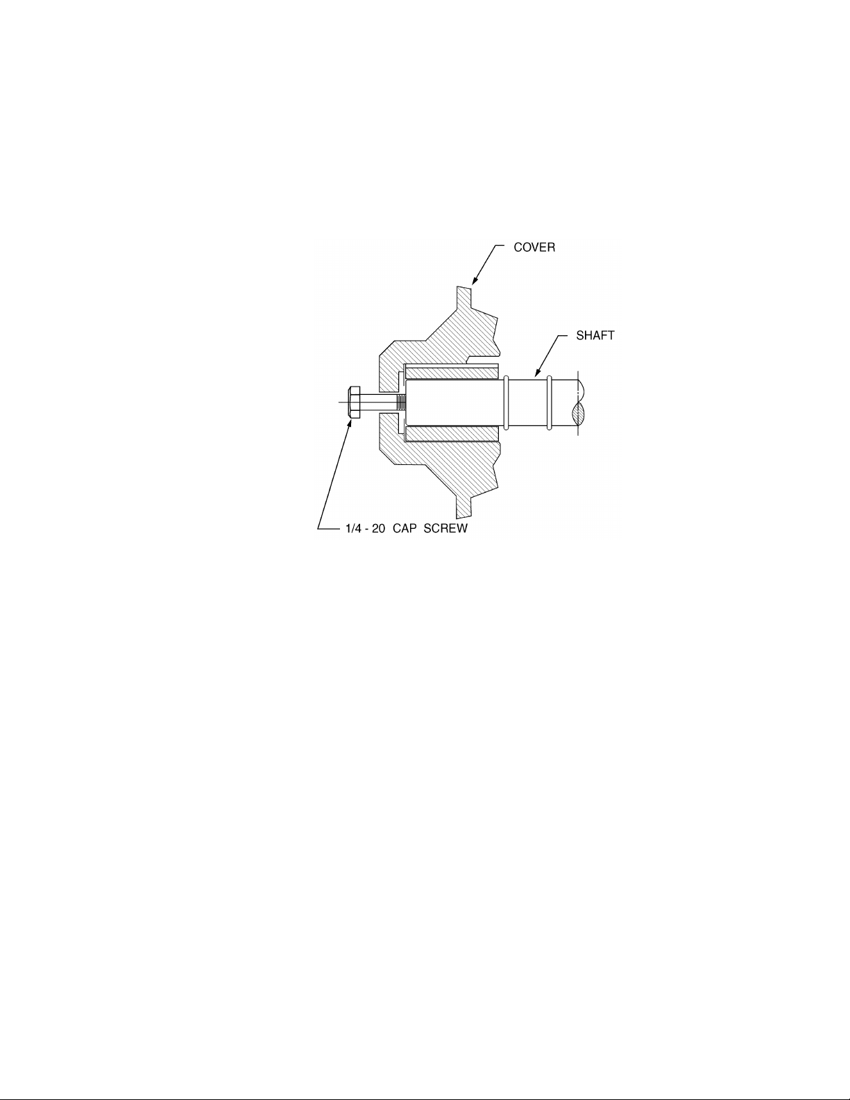
15. Install the Driven Magnet Assembly (item 18) on the drive shaft (item 4).
a) Install the Driven Magnet Assembly inner retaining ring (item 14) by carefully expanding
it over the end of the impeller assembly (item 6) and pushing it along the shaft past the
front groove for the outer retaining ring, which will require that the ring be carefully
expanded no more than necessary to pass the groove before arriving and seating fully in
the back groove.
b) Position the Driven Magnet drive key (item 8) in its keyway.
c) Slide the Driven Magnet Assembly (item 18) on the impeller assembly (item 6). (The flat
side towards the rear housing.)
d) Install the Driven Magnet outer retaining ring (item 14) by carefully expanding it over the
end of the impeller assembly (item 6) and pushing it into the its groove. Verify that the
Magnet Assembly floats freely back and forth between the retaining rings. This requires
that both retaining rings be fully seated in their respective grooves.
Figure 5
16. Install the containment can (item 19) in the casing.
17
Page 23

17. Install a new containment can “O”-ring (item 28) on the back of the rear housing (item 1).
Placing the “O”-ring in warm water prior to installation will momentarily soften the material
making installation easier.
THE MAGNETIC ATTRACTIVE FORCE IS CONSIDERABLE. TAKE CARE NOT TO CHIP THE
MAGNETS AND TO AVOID PINCHING OF FINGERS WHEN THE ASSEMBLY SNAPS TOGETHER.
18. Install the rear housing (item 1) to the casing (item 20).
Magnetic attraction will draw the rear housing and the casing together. The use of four
assembly guide pins screwed into the rear housing is recommended. These pins can be made
from 1/4-28 threaded rod or cut-off bolts.
19. Install the rear housing screws (items 26). Tighten evenly to 72 in. –lb (810 N-cm) in an “X”
pattern in small intervals (do not tighten one side excessively and then tighten the opposite
side, as this will tend to crush the TFE “O”-ring and cause a leak).
20. Omitting the front cover “O”-ring, trial assemble the front cover with no shims (item 3).
a) Install and hand tighten the cover bolts (items 15) evenly.
b) Using feeler gauges, measure and record the gap between the rear housing and the front
cover around the circumference of the pump, between each set of cover bolts.
c) Add the six measurements and divide by six to determine the average clearance between
the two surfaces.
d) Reove the bolts and the front cover. Add shims equal to the measurement obtained in
step “c” above. Red shims are 0.002” thick, and green shims are 0.003” thick. Use no
more shims than necessary, as the pressure capability of the pump is directly related to
the internal clearances between the impeller and the housings.
e) After the shims are in place, install the O-ring (item28) over the inner barrel of the front
cover, seating it fully and smoothly against the shoulder.
f) Install the cover, taking care to avoid damage to the outer bearing (item 9) and ensuring
that the O-ring seats in the rabbet in the rear housing without pinching. Install the cover
bolts (item 15) and tighten to 220 in-lb. (2490 N-cm) using the pattern shown in
Appendix B.
18
Page 24
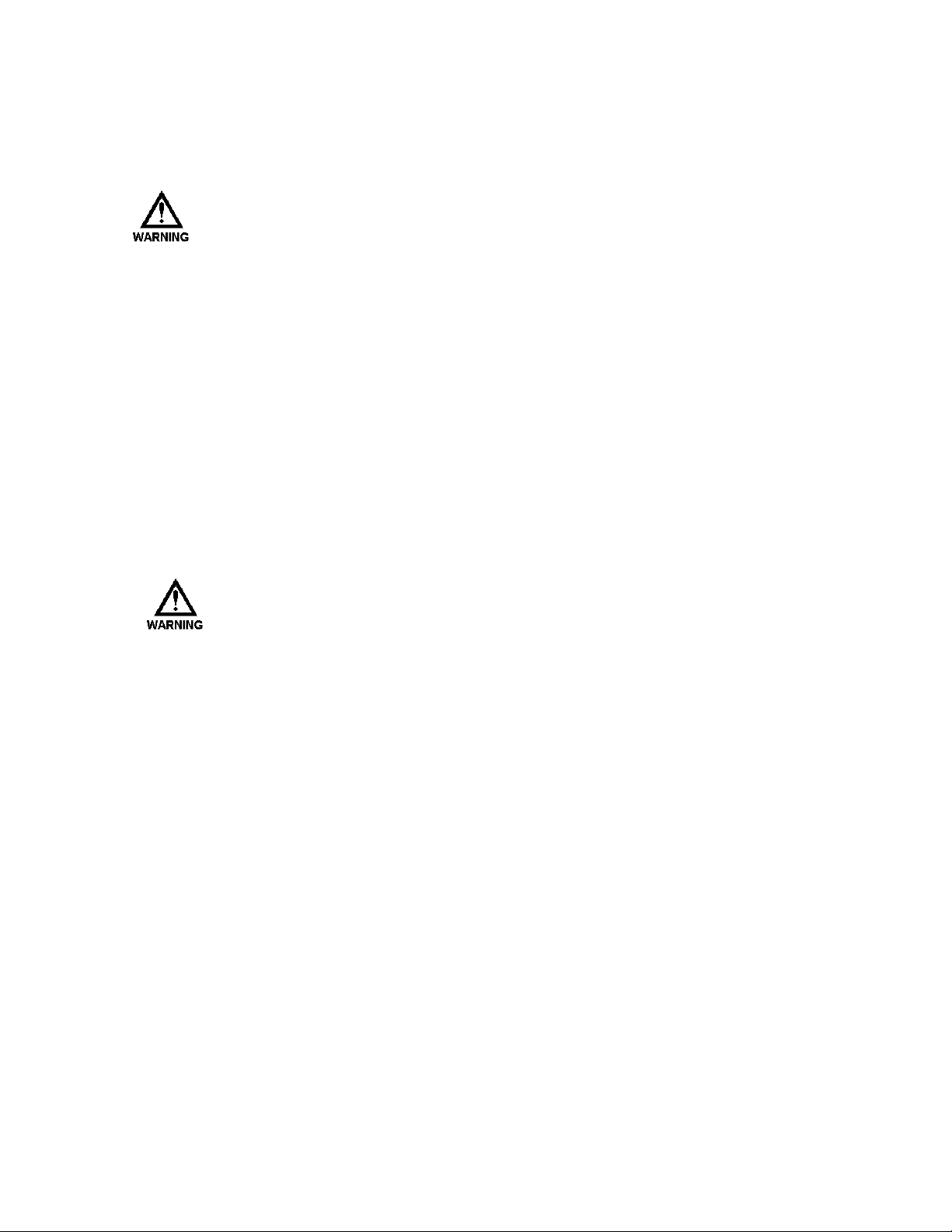
g) Remove the pipe plug (item 27) from the central face of the front cover to expose the
tapped hole in the end of the shaft and thread a 1/4-20 screw into the shaft to rotate the
shaft (refer to Figure 6). With the screw bottomed hand-tight in the shaft, free axial play
of the shaft relative to the impeller can be confirmed by alternately pushing and pulling
the screw. This condition is essential since it confirms that the impeller floats axially on
the shaft. If there is significant resistance to rotation, additional shimming is required,
using a starting value of 0.002”.
Figure 6
h) Remove the screw, and replace the access pipe plug (item 27) using pipe joint compound
or tape.
21. Verify that the rear housing drain plug (item 27) is installed; if not, do so using pipe joint
compound or tape.
22. Refer to the Installation and Startup instructions to return the pump to service.
19
Page 25

6.5.4 Reassembling the No. 12 Pump
Trial fit new magnet assemblies and impellers on the assorted shafts prior to final
assembly. The magnet assembly and impeller must be free to move longitudinally along
the shaft between the retaining rings. Sharp edges especially around key ways may
require hand dressing with a fine file so that this free movement is achieved.
1. If the motor has been removed or replaced, position it on its mounting bracket and tighten.
2. Position the spool (item 29) so that access to the guard screw hole is provided (refer to
Appendix B) and install and tighten the four (4) motor bolts (items 23).
3. Coat the motor shaft with a small amount of anti-seize compound.
4. Slide the drive magnet assembly onto the motor shaft.
5. Align the keyways in the motor shaft and the drive magnet assembly.
6. Slide the shaft key onto the shaft/drive magnet assembly. Position it axially so that the end of
the motor shaft is exactly flush with the face of the drive magnet assembly.
7. Position the casing (item 20) on the spool (item 29).
8. Install and tighten the casing bolts (items 35) to 72 in. –lb (810 N-cm).
9. Rotate the drive magnet assembly by hand, to verify free movement.
If any clearance problem is noted, position the drive magnet assembly accordingly.
10. Coat the set screw with removable thread locking compound.
11. Start the set screw (item 24) in the drive magnet assembly (item 21).
12. Tighten the set screw through a hole in the spool (item 29) to 35 in.-lb (400 N-cm). The
screw socket fits a 1/8” Allen wrench.
Because of the distortion usually applied during removal, all retaining rings should be
replaced for reassembly.
Figure 7
20
Page 26
13. Position the guard (item 36) around the spool (item 29) and insert and tighten the guard screw
(item 37).
14. Install the Driven Magnet Assembly (item 18) on the drive shaft (item 4).
a) Install the Driven Magnet Assembly inner retaining ring (item 14) by carefully expanding
it over the end of the drive shaft (item 4) and pushing it along the shaft past the front
groove for the outer retaining ring, which will require that the ring be carefully expanded
no more than necessary to pass the groove before arriving and seating fully in the back
groove.
b) Position the Driven Magnet drive key (item 8) in its keyway.
c) Slide the Driven Magnet Assembly (item 18) on the driveshaft (item 4). (The flat side
towards the rear housing.)
d) Install the Driven Magnet outer retaining ring (item 14) by carefully expanding it over the
end of the drive shaft (item 4) and pushing it into the its groove.
Verify that the Magnet Assembly floats freely back and forth between the retaining rings.
This requires that both retaining rings be fully seated in their respective grooves.
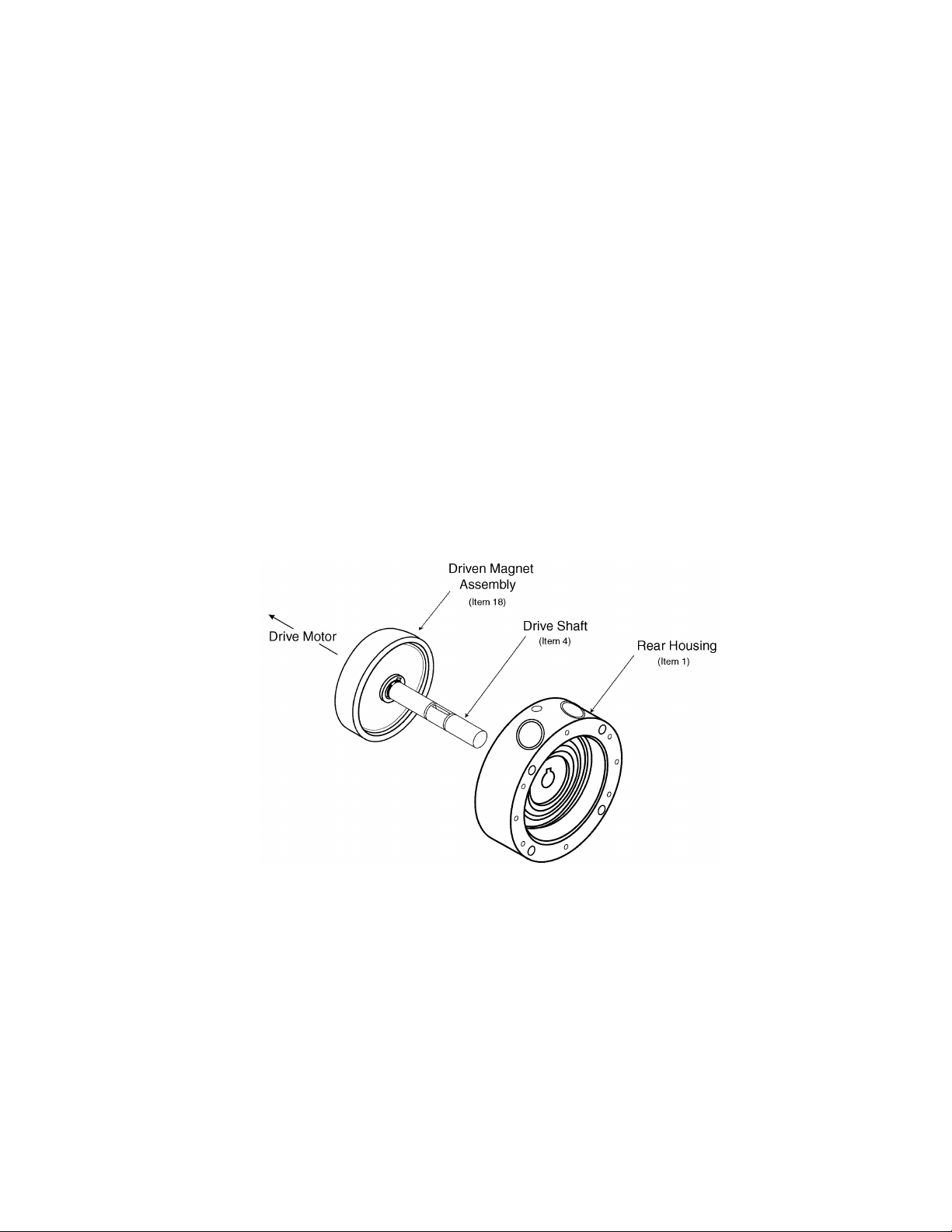
15. Insert the Drive Shaft (item 4) with the Driven Magnet Assembly (item 18) attached into the
back of the rear housing (item 1), taking care to avoid damage to the housing bearing (item
9).
Figure 8
16. Install the Impeller (item 6) on the drive shaft (item 4).
a) Install the Impeller inner retaining ring (item 14).
Carefully expand the retaining ring over the end of the drive shaft (item 4) and push it
along the shaft past the front groove for the outer retaining ring, which will require that
the ring be carefully expanded no more than necessary to pass the groove before arriving
and seating fully in the back groove.
b) Position the Impeller drive key (item 8) in its keyway.
c) Slide the Impeller (item 6) on the drive shaft (item 4).
21
Page 27

d) Install the Impeller outer retaining ring (item 14) by carefully expanding it over the end
of the drive shaft (item 4) and pushing it into the its groove.
Verify that the Impeller floats freely back and forth between the retaining rings. This
requires that both retaining rings be fully seated in their respective grooves.
17. Install the containment can (item 19) in the casing.
18. Install a new containment can “O”-ring (item 28) on the back of the rear housing (item 1).
Placing the “O”-ring in warm water prior to installation will momentarily soften the material
making installation easier.
THE MAGNETIC ATTRACTIVE FORCE IS CONSIDERABLE. TAKE CARE NOT TO CHIP THE
MAGNETS AND TO AVOID PINCHING OF FINGERS WHEN THE ASSEMBLY SNAPS TOGETHER.
19. Install the rear housing (item 1) to the casing (item 20).
Magnetic attraction will draw the rear housing and the casing together. The use of four
assembly guide pins screwed into the rear housing is recommended. These pins can be made
from 1/4-28 threaded rod or cut-off bolts.
20. Install the rear housing screws (items 26). Tighten evenly to 72 in. –lb (810 N-cm) in an “X”
pattern in small intervals (do not tighten one side excessively and then tighten the opposite
side, as this will tend to crush the TFE “O”-ring and cause a leak).
21. Omitting the front cover “O”-ring, trial assemble the front cover with no shims (item 3).
e) Install and hand tighten the cover bolts (items 15) evenly.
f) Using feeler gauges, measure and record the gap between the rear housing and the front
cover around the circumference of the pump, between each set of cover bolts.
g) Add the six measurements and divide by six to determine the average clearance between
the two surfaces.
h) Reove the bolts and the front cover. Add shims equal to the measurement obtained in
step “c” above. Red shims are 0.002” thick, and green shims are 0.003” thick. Use no
more shims than necessary, as the pressure capability of the pump is directly related to
the internal clearances between the impeller and the housings.
i) After the shims are in place, install the O-ring (item28) over the inner barrel of the front
cover, seating it fully and smoothly against the shoulder.
j) Install the cover, taking care to avoid damage to the outer bearing (item 9) and ensuring
that the O-ring seats in the rabbet in the rear housing without pinching. Install the cover
bolts (item 15) and tighten to 220 in-lb. (2490 N-cm) using the pattern shown in
Appendix B.
22
Page 28

k) Remove the pipe plug (item 27) from the central face of the front cover to expose the
tapped hole in the end of the shaft and thread a 1/4-20 screw into the shaft to rotate the
shaft (refer to Figure 9). With the screw bottomed hand-tight in the shaft, free axial play
of the shaft relative to the impeller can be confirmed by alternately pushing and pulling
the screw. This condition is essential since it confirms that the impeller floats axially on
the shaft. If there is significant resistance to rotation, additional shimming is required,
using a starting value of 0.002”.
Figure 9
l) Remove the screw, and replace the access pipe plug (item 27) using pipe joint compound
or tape.
22. Verify that the rear housing drain plug (item 27) is installed; if not, do so using pipe joint
compound or tape.
23. Refer to the Installation and Startup instructions to return the pump to service.
23
Page 29

7. Troubleshooting Guide
Symptom Probable Cause Remedy
No Liquid Delivered
Low Liquid Delivery
Low Discharge
Pressure
Pump Gradually
Loses Prime
Pump Noisy
Motor runs hot or
Overloads
Pump not primed. Prime pump.
Motor Incorrectly wired. Check wiring diagram.
Air leak in suction. Locate and repair.
Rotation direction incorrect. Reverse rotation.
Suction and/or discharge
valves closed.
Suction lift too high. Do not exceed vapor pressure of liquid.
Magnetic coupling decoupled. Stop motor, eliminate blockage or jamming and restart. If no
Discharge head higher than
calculated.
Air leak in suction. Repair leak.
Rotational speed incorrect. Check speed and wiring.
Rotation direction incorrect. Reverse rotation.
Suction lift too high. Increase suction pressure.
Impeller or housing worn. Inspect and repair as required.
Wear plates worn. Inspect and repair as required.
Rotational speed incorrect. Check Speed.
Air leak in suction. Repair leak.
Air or gas in liquid. Eliminate air or gas.
Impeller or Housing worn. Inspect and repair as required.
Wear plates worn. Inspect and repair as required.
Air pocket in suction line. Eliminate pocket.
Air entering suction line. Keep suction inlet submerged at all times.
Pump worn or damaged. Inspect and repair as required.
Air or gas in liquid. Eliminate air or gas.
It is normal for motors to feel
hot even when not overloaded.
Motor wired incorrectly. Check wiring diagram.
Voltage or frequency low. Correct condition.
Motor not sized correctly for
the flow.
Heavy or viscous liquid being
pumped.
Binding internal pump parts. Inspect and correct condition.
Open valves.
blockage exists verify that operating conditions do not exceed
capabilities of the pump. If de-coupling persists upon startup,
a “soft-start” motor starter may be required to accommodate a
fast-starting or oversized motor.
Reduce discharge restrictions eg: Open throttle valve.
Check the actual temperature of the motor housing with
suitable instrumentation. Verify the figures with the motor
manufacturer.
Higher pressures may require more power than the motor is
capable of.
Pumping fluids heavier or more viscous than water requires a
larger motor.
24
Page 30

Appendix A – Specifications
Pump Model RGT 10 RGT 12
Maximum Flow, GPM (LPM) @ 3450 RPM 14.5 (55.0) 23.3 (88.3)
Maximum Flow, GPM (LPM) @ 2875 RPM 11.0 (41.7) 19.0 (72.0)
Maximum Flow, GPM (LPM) @ 1725 RPM 4.5 (17.1) 9.8 (37.1)
Maximum Head, FT ( METERS) 427 (130) 693 (211)
Maximum Discharge Pressure, PSIG (Bar) 300 (20.7) 300 (20.7)
Maximum Suction Pressure, PSIG (Bar) 100 (6.9) 100 (6.9)
Suction Size 1” FNPT/FBSPT 1” FNPT/FBSPT
Discharge Size 1” FNPT/FBSPT 1” FNPT/FBSPT
Temperature Range, Neodymium -150º to +300º F
-101º to +149º C
Temperature Range, Samarium -150º to +450º F
-101º to +232º C
Maximum Viscosity* cp 100 100
Speeds RPM 3450, 2875, 1725 3450, 2875, 1725
Weight, LBS, (KG) 36 (16.40) 40 (18.1)
Maximum Power 5 HP 7-1/2 HP
-150º to +300º F
-101º to +149º C
-150º to +450º F
-101º to +232º C
*Consult factory for viscosity requirements higher than 100 cp
Appendix B – Bolt Pattern
1. Torque all six fasteners to 110 in-lbs (12.4 N-m) first, following the sequence in the Figure 10
below.
2. Then torque all fasteners to the final value of 220 in-lbs (24.8 N-m), again following the same
sequence.
Figure 10
25
Page 31
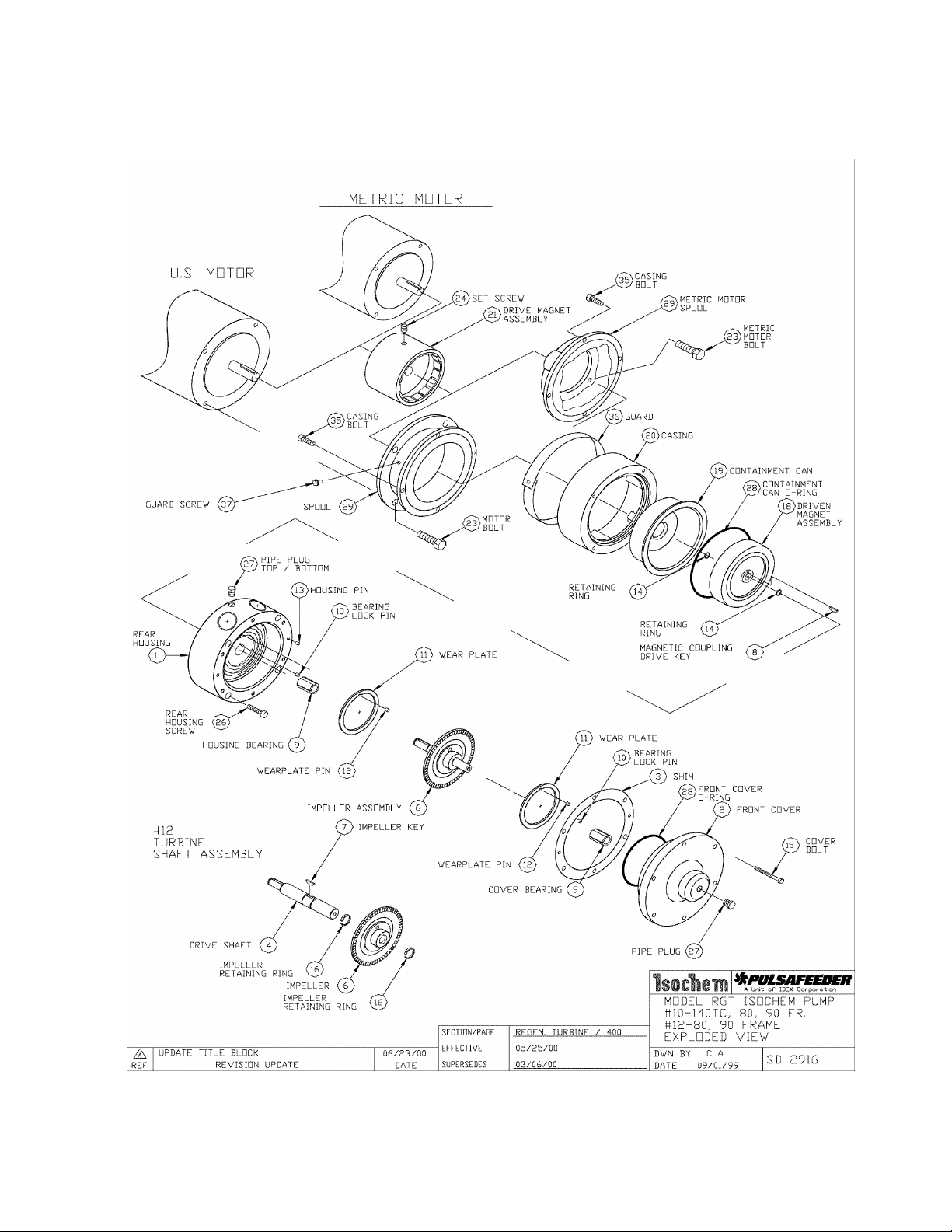
Appendix C – Exploded Drawing
26
Page 32

27
Page 33

28
Page 34

Appendix D – Options
POSITION 1 REGENERATIVE TURBINE MAGNETICALLY DRIVEN SEALLESS
RGT = C-FACE MOTOR MOUNTING ASSEMBLY. (1) – 10, 12
POSITION 2 PUMP SIZE 10 12
Port Size Inches FNPT/BSPT
Capacity MAX. GPM (M3/H)
Differential Head MAX. Ft. (M)
POSITION 3 AVAILABLE PUMP METAL AND TYPE PORT CONNECTION
A = 316SS FNPT
C = ALLOY C FNPT
K = 316SS FBSPT
M = ALLOY C FBSPT
POSITION 4 IMPELLER AND SHAFT MATERIAL
A = 316SS
C = ALLOY C
POSITION 5 WEAR PLATE MATERIAL
L = Carbon
T = TFE (Glass Filled) (2)
POSITION 6 BEARING MATERIAL
K = Standard Carbon
L = Extended Life Carbon
T = TFE (Glass Filled) (2)
POSITION 7 MAG DRIVE MOUNTING ARRANGEMENT
0 = 143TC– 184C FRAME (U.S.) (3)
R = 182-184TC FRAME (U.S.)
W = 213-215TC FRAME (U.S.)
K = 80 FRAME, (∅100mm B.C. ) (Metric)
L = 90 FRAME, (∅115mm B.C. ) (Metric)
POSITION 8 OPTIONS
B = PFA Coated SS Hsg O-Rings, Metallic Bearing, Wearplate Lock Pins, and Spacer Shim
Assembly. (Required for temperatures above 200°F (93°C)
H = PFA Coated SS Hsg O-Rings / Metallic Bearing, Wearplate Lock Pins and Spacer Shim
Assembly. Samarium Cobalt Magnets (Required for temperatures above 300°F (149°C)
M = Alloy C Containment Can (For 316SS Construction Pumps) X X
S = Samarium Cobalt Magnet X X
W = Welded Driven Magnet Assy (Samarium Cobalt Magnets ONLY) X X
POSITION 9 OPTIONS
Consult your local representative for options to meet your special requirements.
Notes:
1.) All pumps require motors with feet..
2.) Only for temperatures below 110°F (43°C).
3.) Pedestal assembly A123208 with a foot-mounted motor is optional.
Use “O” in position 7 of the pump model number. Pedestal to be ordered as a separate line item.
1.00”
14.5 (3.29)
427 (130)
X
X
X
X
X
X
X
X
X
X
X
X
X
X
X
X X
X X
1.00”
23.3 (5.29)
693 (211)
X
X
X
X
X
X
X
X
X
X
X
X
X
X
X
X
29
Page 35

Appendix E – Bill of Materials
SECTION: REGENERATIVE TURBINE
ISOCHEM RGT SERIES PUMP
CONSOLIDATED BILL OF MATERIALS
POSITION 3 STANDARD PUMP METALLURGIES, PORT CONN
DESCRIPTION QTY PART No. MATL PART No. MATL ITEM
POSITION 2 PUMP SIZE – NON-VARIABLE COMPONENTS
10
12
STANDARD PUMP – NON-VARIABLE COMPONENTS
POSITIONS 8, 9 OPTIONS – DELETE CORRESPONDING STANDARD PUMP COMPONENT FROM THE BILL OF MATERIALS
B
M CONTAINMENT CAN 1 49605 Alloy C – – – – – – 19
+ SPACER, SHIM ASSY 1 Y1400400-000 188SS Y1400400-000 188SS 3
DRVN MAG ASSY (O-RING) / (SAMAR) 1 49616 316SS 49643 Alloy C 18
H HIGH TEMPERATURE APPLICATION COMBINE PUMP OPTIONS B AND S
W
* COMPONENT QUANTITY MAY BE CUMULATIVE OVER THE ENTIRE BILL OF MATERIALS
+ DENOTES RECOMMENDED SPARE PART.
COVER, FRONT 1 Y0202100-316 316SS Y0202100-HCO ALLOY C 2
HOUSING, REAR (A, C) FNPT Y0502300-316 316SS Y0502300-HCO ALLOY C
HOUSING, REAR (K, M) BFNPT
COVER, FRONT 1 Y0202200-316 316SS Y0202200-HCO ALLOY C 2
HOUSING, REAR (A, C) FNPT Y0502400-316 316SS Y0502400-HCO ALLOY C
HOUSING, REAR (K, M) BFNPT
+ SPACER, SHIM ASSY 1 Y1400300-000 POLYEST Y1400300-000 POLYEST 3
+ RING, RETAINING DRV. MAG.
+ KEY, MAGNETIC CPLG – DRIVEN 1 41933 ALLOY 20 41934 ALLOY C 8
+ PIN, BEARING LOCK
+ PIN, WEARPLATE LOCK *2 41801 TFE 41801 TFE 12
+ O-RING, COVER *1 W209729-TFE TFE W209729-TFE TFE 28
PIN, HOUSING *2 41802 ALLOY 20 41802 ALLOY 20 13
SCREW, REAR HOUSING 4 W770269-STA STL W770269-STA STL 26
BOLT, FRONT COVER 6 W770426-188 188SS W770426-188 188SS 15
PLUG, 1/8” NPT 3 W772565-316 316SS 52301 ALLOY C 27
NAMEPLATE 1 41210 188SS 41210 188SS --
+ PIN, BEARING LOCK
+ PIN, WEARPLATE LOCK *2 41802 Alloy 20 41806 Alloy C 12
+ 0-RING, COVER / CNTNMNT CAN 2 41112 SS/PFA 41112 SS/PFA 28
DRV MAG ASSY 140TC FR (S) #10 Y1900900-000 STL Y1900900-000 STL
S
DRV MAG ASSY 140-80TC FR (S) #12 49604-3 STL 49604-3 STL
DRV MAG ASSY, 80 FR (S) 49735 STL 49735 STL
DRV MAG ASSY 90 FR (S)
DRVN MAG ASSY (WELDED) / (SAMAR) 1 49660 316SS 49659 Alloy C 18
#10 *2 46713 ALLOY 20 46701 ALLOY C
#12 1 46713 ALLOY 20 46701 ALLOY C
#10 41801 TFE 41801 TFE
#12
#10 41802 Alloy 20 41806 Alloy C
#12
1
1
*2
*2
1
PAGE: 200
EFFECTIVE: 06/27/00
SUPERSEDES: 03/06/00
316SS
(A) OR (K)
Y0502500-316 316SS Y0502500-HCO ALLOY C
Y0502600-316 316SS Y0502600-HCO ALLOY C
41811 TFE 41811 TFE
41812 Alloy 20 41813 Alloy C
49736 STL 49736 STL
ALLOY C
(C) OR (M)
1
1
14
10
10
21
30
Page 36
SECTION: REGENERATIVE TURBINE
ISOCHEM RGT SERIES PUMP
CONSOLIDATED BILL OF MATERIALS
POSITION 3 STANDARD PUMP METALLURGIES
DESCRIPTION QTY PART No. MATL PART No. MATL ITEM
POSITION 4 IMPELLER AND SHAFT MATERIAL
+ IMPELLER ASSEMBLY Y0101000-316 316SS ------------ ------ IMPELLER Y0100800-316 316SS ------------ ------ SHAFT, DRIVE Y0704100-316 316SS ------------ -------
A
C
POSITION 5 WEAR PLATE MATERIAL
L + WEAR PLATE Y2000100-000 EWCBN Y2000100-000 EWCBN
T + WEAR PLATE
POSITION 6 BEARING MATERIAL
K + BEARING, SHAFT
L + BEARING, SHAFT
T + BEARING, SHAFT
KEY, IMPELLER 41933-1 Alloy 20 ------------ ------ RING, RETAINING
+ IMPELLER 1 Y0100900-316 316SS ------------ ------- 6
+ SHAFT, DRIVE 1 Y0704200-316 316SS ------------ ------- 4
+ KEY, IMPELLER 1 41933-1 Alloy 20 ------------ ------- 7
+ RING, RETAINING
+ IMPELLER ASSEMBLY Y0101000-HCO Alloy C Y0101000-HCO Alloy C
IMPELLER Y0100800-HCO Alloy C Y0100800-HCO Alloy C
SHAFT, DRIVE Y0704100-HCO Alloy C Y0704100-HCO Alloy C
KEY, IMPELLER 41931-1 Alloy C 41934-1 Alloy C
RING, RETAINING
+ IMPELLER 1 Y0100900-HCO Alloy C Y0100900-HCO Alloy C 6
+ SHAFT, DRIVE 1 Y0704200-HCO Alloy C Y0704200-HCO Alloy C 4
+ KEY, IMPELLER 1 41934-1 Alloy C 41934-1 Alloy C 7
+ RING, RETAINING
#10 1
#12
*2 46710 Alloy 20 ------------ ------- 16
#10 1
#12
*2 46711 Alloy C 46711 Alloy C 16
2
Y2000100-FTF TFE(GF) Y2000100-FTF TFE(GF)
#10 40426 CARBON 40426 CARBON
#12
#10 40430 EWCBN 40430 EWCBN
#12
#10 40425 TFE (GF) 40425 TFE (GF)
#12
2
2
2
PAGE: 201
EFFECTIVE: 06/27/00
SUPERSEDES: 03/06/00
316SS
(A) OR (K)
46713 Alloy 20 ------------ -------
46701 Alloy C 46701 Alloy C
40436 CARBON 40436 CARBON
40437 EWCBN 40437 EWCBN
40438 TFE (GF) 40438 TFE (GF)
ALLOY C
(C) OR (M)
6
6
11
9
* COMPONENT QUANTITY MAY BE CUMULATIVE OVER THE ENTIRE BILL OF MATERIALS
+ DENOTES RECOMMENDED SPARE PART.
31
Page 37

SECTION: REGENERATIVE TURBINE
ISOCHEM RGT SERIES PUMP
CONSOLIDATED BILL OF MATERIALS
POSITION 3 STANDARD PUMP METALLURGIES
DESCRIPTION QTY PART No. MATL PART No. MATL ITEM
POSITION 7 NEODYMIUM MAGNETIC COUPLING COMPONENTS
DRIVEN MAGNET ASSY (0-RING) 1 49738 316SS 49739 ALLOY C 18
COMMON
PARTS
140TC FRAME COMPONENTS **
O
180 – 210 TC FRAME COMPONENTS
COMMON
PARTS
180TC FRAME COMPONENTS
R
210TC FRAME COMPONENTS
W
CONTAINMENT CAN 1 49672 316SS 49605 ALLOY C 19
CASING 1 49610-1 ALU 49610-1 ALU 20
BOLT, CASING *4 16722 STL 16722 STL 35
+ O-RING, CNTNMNT CAN *1 W209729-TFE TFE W209729-TFE TFE 28
DRIVE MAGNET ASSY, 140TC FR 1 Y1900600-000 STL Y1900600-000 STL 21
SET SCREW, DRIVE MAGNET ASSY 1 W771004-019 STL W771004-019 STL 24
MOTOR SPOOL 1 49750 ALU 49750 ALU 29
#10
GUARD 1 Y9601600-000 ABS Y9601600-000 ABS 36
SCREW, GUARD 1 W208894-STL STL W208894-STL STL 37
BOLT, MOTOR 4 W770424-STL STL W770424-STL STL 23
DRIVE MAGNET ASSEMBLY 1 49731-3 STL 49731-3 STL 21
DRIVE MAGNET, HOLDER 1 Y1901200-STL STL Y1901200-STL STL 30
SET SCREW, HOLDER 2 W771004-019 STL W771004-019 STL 24
SCREW, HOLDER 2 W770027-STA STL W770027-STA STL 31
#12
DOWEL PIN, HOLDER 2 W771209-003 STL W771209-003 STL 32
MOTOR ADAPTOR COVER 1 Y1101200-ALU ALU Y1101200-ALU ALU 29A
MOTOR ADAPTOR 1 Y1101300-ALU ALU Y1101300-ALU ALU 29
BOLT, ADAPTOR COVER *6 16722 STL 16722 STL 35
BOLT, MOTOR 4 W770424-STL STL W770424-STL STL 23
DRIVE MAGNET ASSEMBLY 1 49731-3 STL 49731-3 STL 21
MOTOR, ADAPTOR 1 Y1101100-ALU ALU Y1101100-ALU ALU 29
SCREW, HOLDER 2 W770027-STA STL W770027-STA STL 31
DOWEL PIN, HOLDER 2 W771209-003 STL W771209-003 STL 32
DRIVE MAGNET HOLDER 1 Y1901100-STL STL Y1901100-STL STL 30
SET SCREW, HOLDER 2 W771004-030 STL W771004-030 STL 24
SCREW, MOTOR 4 W770070-STA STL W770070-STA STL 23
RING, ADAPTOR 180TC-210TC 1 Y1101400-ALU ALU Y1101400-ALU ALU 38
DRIVE MAGNET HOLDER 1 Y1901300-STL STL Y1901300-STL STL 30
SET SCREW, HOLDER 2 W771004-046 STL W771004-046 STL 24
SCREW, MOTOR 4 W770072-STA STL W770072-STA STL 23
* COMPONENT QUANTITY MAY BE CUMULATIVE OVER THE ENTIRE BILL OF MATERIALS
+ DENOTES RECOMMENDED SPARE PART.
** USE THESE MOTOR FRAME COMPONENTS WHEN USING POWER FRAME ASSEMBLY A123208
PAGE: 202
EFFECTIVE: 06/27/00
SUPERSEDES 03/06/00
316SS
(A) OR (K)
ALLOY C
(C) OR (M)
32
Page 38
SECTION: REGENERATIVE TURBINE
ISOCHEM RGT SERIES PUMP
CONSOLIDATED BILL OF MATERIALS
POSITION 3 STANDARD PUMP METALLURGIES
DESCRIPTION QTY PART No. MATL PART No. MATL ITEM
POSITION 7 NEODYMIUM MAGNETIC COUPLING COMPONENTS (CONT)
DRIVEN MAGNET ASSY (0-RING) 1 49738 316SS 49739 ALLOY C 18
COMMON
PARTS
80 METRIC FRAME COMPONENTS
K
90 METRIC FRAME COMPONENTS
L
CONTAINMENT CAN 1 49672 316SS 49605 ALLOY C 19
CASING 1 49610-1 ALU 49610-1 ALU 20
BOLT, CASING *4 16722 STL 16722 STL 35
+ O-RING, CNTNMNT CAN *1 W209729-TFE TFE W209729-TFE TFE 28
DRIVE MAGNET ASSY, 80 FR 1 49733 STL 49733 STL 21
MOTOR SPOOL 1 49727 ALU 49727 ALU 29
BOLT, MOTOR 4 NP990415-STL STL NP990415-STL STL 25
DRIVE MAGNET ASSY, 90 FR 1 49734 STL 49734 STL 21
MOTOR SPOOL 1 49728 ALU 49728 ALU 29
BOLT, MOTOR 4 NP990478-STL STL NP990478-STL STL 25
PAGE: 203
EFFECTIVE: 08/03/00
SUPERSEDES NEW
316SS
(A) OR (K)
ALLOY C
(C) OR (M)
* COMPONENT QUANTITY MAY BE CUMULATIVE OVER THE ENTIRE BILL OF MATERIALS
+ DENOTES RECOMMENDED SPARE PART.
33
Page 39

Appendix F – Power Frame Assembly
34
Page 40

Power Frame Maintenance
General Maintenance:
Fill power frame oil cup (item 9) to the “oil level” line, about ½” from the top edge of the cup. Use
standard motor oil, SAE-10W-40, 10W-30, SW-30, or equivalent.
Drain and change oil after every 2,000 hours of operation. Increase frequency of oil changes if operating
in an adverse environment, for example high moisture, very high or low temperatures, etc.
Disassembly:
1. Remove bearing cap bolts (item 6)
2. Slide bearing cap (item 5) out of housing and over the end of the shaft (item 2)
3. Remove shaft/bearing assembly by sliding out of housing
Reassembly:
1. Press new bearings (item 3 both ends) onto shaft if replacement is required
2. Inspect the surface of the shaft (item 2) for burrs and scratches, clean and smooth as required.
3. Press new lip seals (item 7) into housing and bearing cap. Apply grease to the inside diameter of
the lip seals.
4. Install a new gasket (item 4) on the bearing cap.
5. Slide the shaft/bearing assembly into the power frame housing. The end stamped “F” must be
towards the bearing cap.
6. Shim if required to obtain shaft end-play of 0.000 – 0.004 inches.
7. Replace the bearing cap bolts (item 6) and tighten.
8. Refill with oil as per instructions above.
35
Page 41

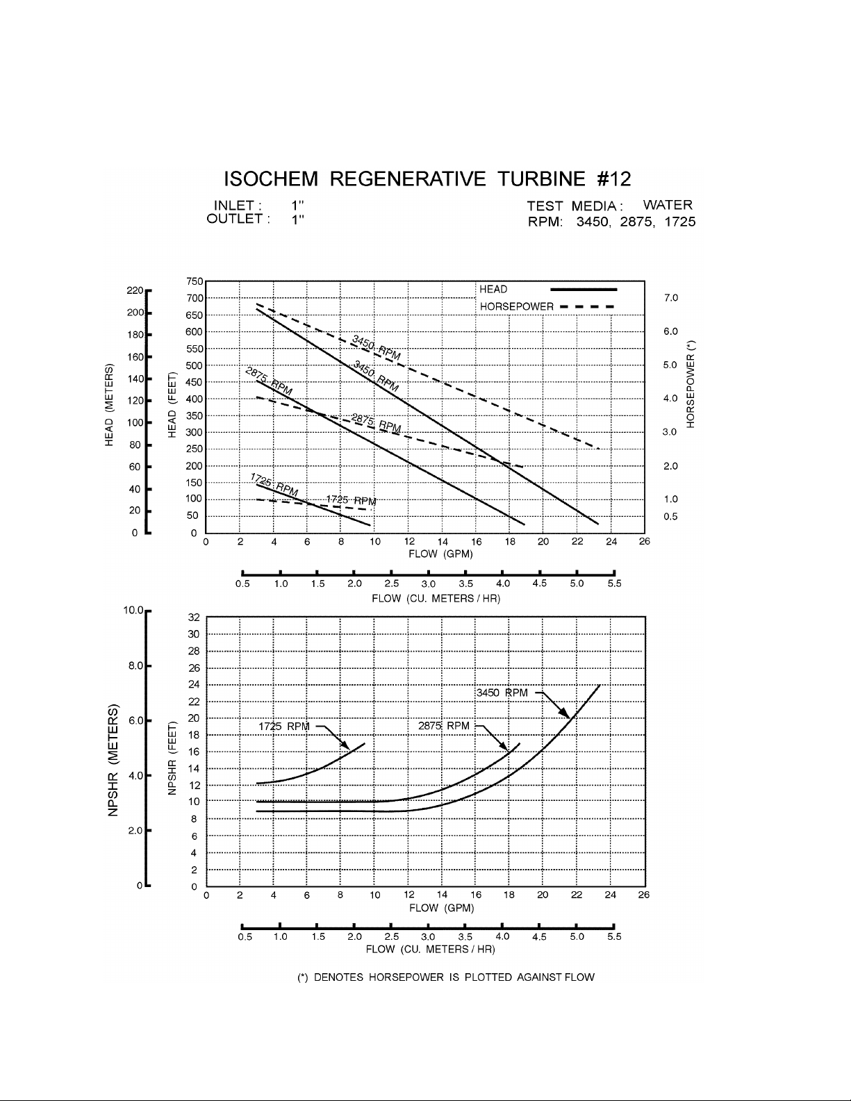
Appendix G – Performance Curves
36
Page 42
37
Page 43

38
Page 44

Bulletin #: IOM – RGT0700 - Rev. C
Engineered Pump Operations
2883 Brighton-Henrietta Townline Road
Rochester, New York 14623
Telephone: (585) 292-8000 Fax: (585) 424-5619
http: //www.pulsa.com pulsa@idexcorp.com
 Loading...