

Page 1
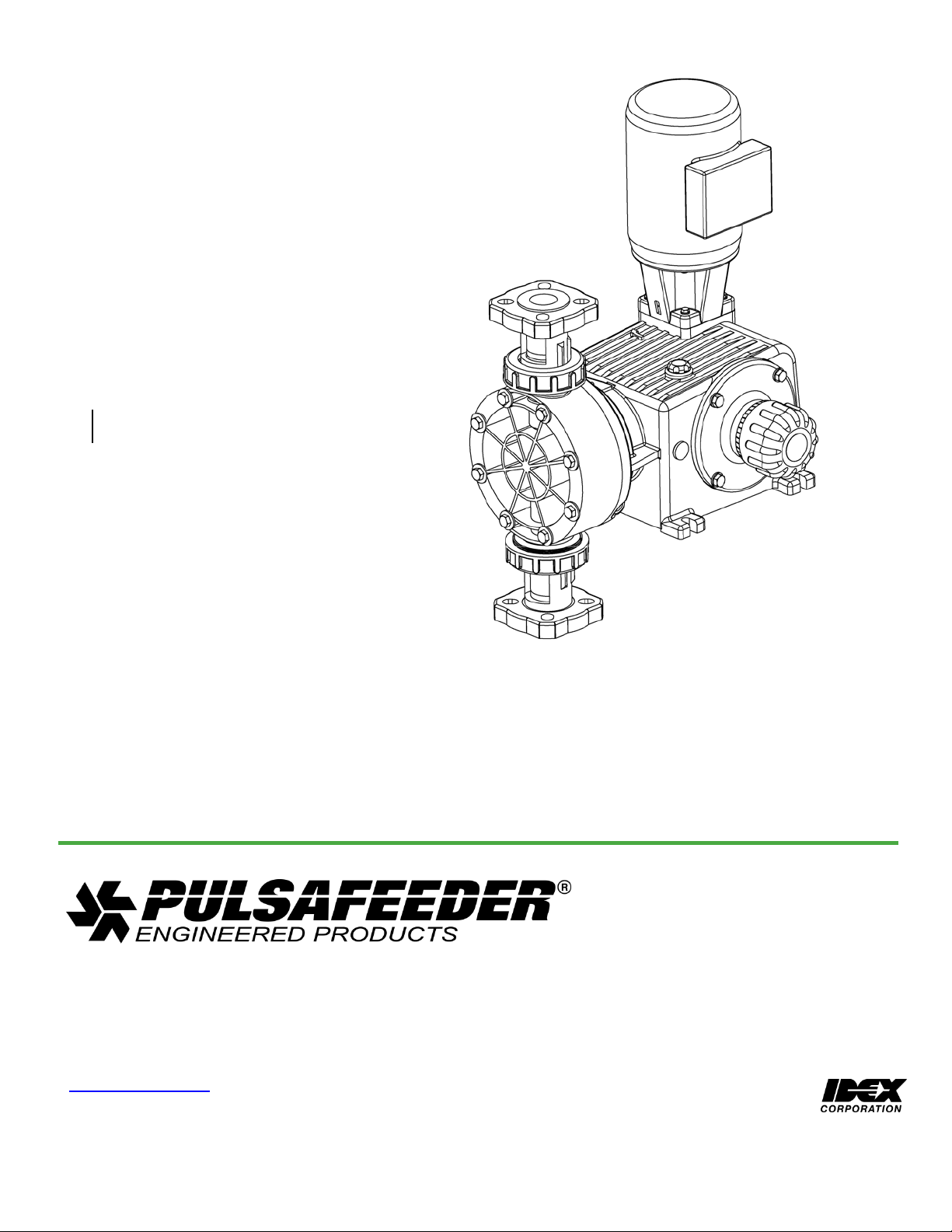
PULSA GLM®
Bulletin #: IOM-GLM-DM7-001
Installation, Operation &
Maintenance Instruction
Models: GLM7
MECHANICAL DI AP HRAGM
METERING PUMP
Page 2

Pulsafeeder Factory Service Policy
Should you experience a problem with your Pulsafeeder pump, first consult the troubleshooting
guide in your operation and maintenance manual. If the problem is not covered or cannot be
solved, please contact your local Pulsafeeder Sales Representative or Distributor, or our
Technical Services Department for further assistance.
Trained technicians are available to diagnose your problem and arrange a solution. Solutions
may include purchase of replacement parts or returning the unit to the factory for inspection and
repair. All returns require a Return Authorization number to be issued by Pulsafeeder. Parts
purchased to correct a warranty issue may be credited after an examination of original parts by
Pulsafeeder. Warranty parts returned as defective which test good will be sent back freight
collect. No credit will be issued on any replacement electronic parts.
Any modifications or out-of-warranty repairs will be subject to bench fees and costs
associated with replacement parts.
Safety Considerations:
1. Read and understand all related instructions and documentation before attempting to install or
maintain this equipment
2. Observe all special instructions, notes, and cautions.
3. Act with care and exercise good common sense and judgment during all installation,
adjustment, and maintenance procedures.
4. Ensure that all safety and work procedures and standards that are applicable to your company
and facility are followed during the installation, maintenance, and operation of this equipment.
Copyright ©2014 Pulsafeeder, Inc. All rights reserved.
Information in this document is subject to change without notice. No part of this publication may
be reproduced, stored in a retrieval system or transmitted in any form or any means electronic or
mechanical, including photocopying and recording for any purpose other than the purchaser’s
personal use without the written permission of Pulsafeeder, Inc.
2
Page 3

Table of Contents
1. INTRODUCTION ................................................................................................................................................ 4
2. PRINCIPLES OF OPERATION .......................................................................................................................... 4
2.1 Reagent Head Assembly ....................................................................................................................... 5
2.2 Control Assembly .................................................................................................................................. 5
2.3 Gear Ratio Assembly ............................................................................................................................. 5
3. EQUIPMENT INSPECTION ................................................................................................................................ 6
4. STORAGE .......................................................................................................................................................... 6
5. INSTALLATION ................................................................................................................................................. 6
5.1 Location .................................................................................................................................................. 6
5.2 Piping System ........................................................................................................................................ 7
5.3 Suction Pressure Requirements ........................................................................................................... 7
5.4 Discharge Pressure Requirements ....................................................................................................... 8
6. EQUIPMENT STARTUP ..................................................................................................................................... 9
6.1 Fastener Inspection ............................................................................................................................... 9
6.2 Output Adjustment ................................................................................................................................. 9
6.3 Oil Fill and Maintenance ...................................................................................................................... 10
6.4 Priming the Reagent Head .................................................................................................................. 11
6.5 Calibration ............................................................................................................................................ 13
7. MAINTENANCE ............................................................................................................................................... 14
7.1 Diaphragm Removal & Reinstallation ................................................................................................ 16
7.2 Diaphragm Shaft Seal .......................................................................................................................... 18
7.3 Check Valves ........................................................................................................................................ 19
7.4 Check Valve Removal & Reinstallation, Plastic Union-Nut type ...................................................... 20
7.5 Check Valve Removal and Reinstallation, Metal Tie-Bar type.......................................................... 21
7.6 Motor Removal & Reinstallation ......................................................................................................... 23
8. REPLACEMENT PARTS ................................................................................................................................. 24
8.1 KOPkit Program ................................................................................................................................... 24
8.2 Ordering KOPkits or Parts .................................................................................................................. 24
8.3 KOPkit numbers by model .................................................................................................................. 25
9. MODEL NUMBER IDENTIFICATION ............................................................................................................... 25
10. TROUBLESHOOTING ..................................................................................................................................... 26
11. PIPING ACCESSORIES ................................................................................................................................... 28
12. DIMENSIONAL DRAWIN G .............................................................................................................................. 29
13. PARTS DIAGRAMS AND PARTS LISTS ........................................................................................................ 31
3
Page 4
1. Introduction
The GLM® DM7 m etering pump is positive displacement, mechanically operated
reciprocating diaphragm pump. Each pump consists of a power end and a process
end separated by a Teflon faced diaphragm. Individual pumps will vary in appearance
due to various liquid ends and accessories; however, the basic principles of operation
remain the same.
2. Principles of Operation
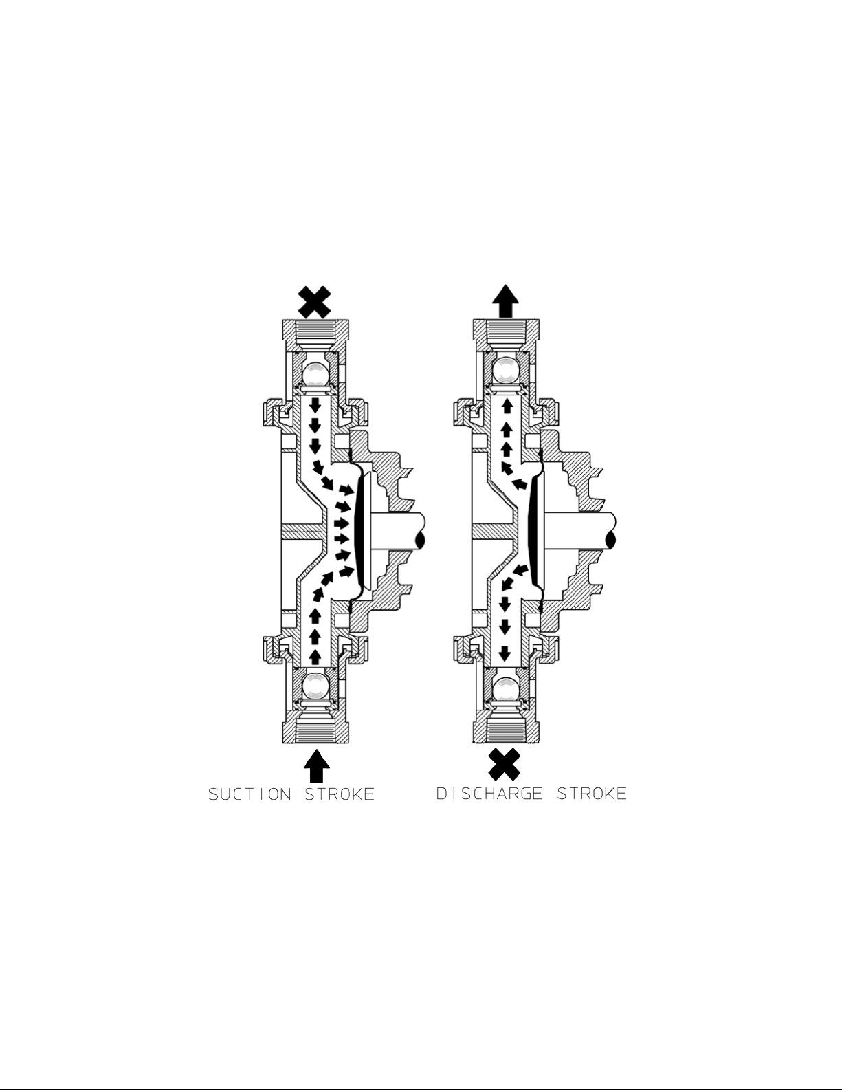
Figure 1, reagent head
operation
A diaphragm reciprocates at a preset stroke length, displacing an exact volume of
process fluid. Diaphragm retraction causes the product to enter through the suction
check valve. Diaphragm advance causes the discharge of an equal amount of the
product through the discharge check valve.
4
Page 5
2.1 Reagent Head Assembly
The typical reagent head assembly consists of reagent head, diaphragm, and
suction and discharge cartridge check valves. This assembly is the only part of the
pump to contact the process liquid; consequently, maintenance is critical to pump
performance.
2.2 Control Assembly
The GLM® DM7 pump incorporates a full motion style of stroke length adjustment.
The stroke length setting is indicated by a (0% – 100%) scale located on the stroke
adjustment assembly.
Stroke length is changed by loosening the locking screw and turning the hand knob.
This turns a mechanism, which changes the amplitude of the stroke length. As the
stroke adjustment knob is turned towards 100%, it displaces the cam eccentrically
to the rotating drive shaft. This in turn causes the pushrod and diaphragm to travel
over a longer distance. Refer to Section 6.2 for further information.
For automatic flow rate control, users can consider the Pulsafeeder MPC speed
based control system, please contact your local Pulsafeeder dealer or representative
for more information.
2.3 Gear Ratio Assembly
GLM® DM7 pumps are driven by an electric motor mounted on the motor adaptor input
flange. The
motor drives a set of worm gears that convert rotational speed into torque.
They, in turn, power the eccentric shaft assembly that converts rotary motion into
reciprocating motion.
lubricating oil bath.
The gear assembly and eccentric shaft run submerged in a
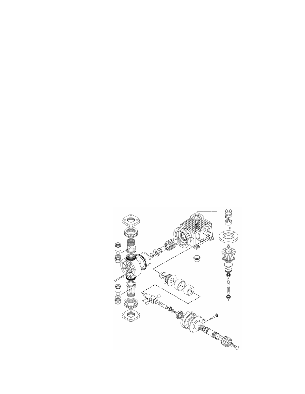
Figure 2, isometric view
5
Page 6

3. Equipment Inspection
Check all equipment for completeness against the order and for any evidence of shipping
damage. Shortages or damage must be reported immediately to the carrier and your
authorized representative or distributor of GLM
4. Storage
4.1.1 Short Term
Storage of your GLM® DM7 pump for up to 12 months is considered short-term.
4.1.2 Long Term
The recommended short-term storage procedures are:
a. Store the pump indoors at room temperature in a dry environment.
b. The lubricating oil should be added to the gearbox prior to storage
c. If required by the operating environment, take precautions to prevent entry of
water or humid air into the eccentric enclosure.
d. Prior to startup, perform a complete inspection and then start up in accordance
with instructions in this manual.
Every twelve months, in addition to the above short-term procedures, power up the
motor and operate the pump for a minimum of one hour. It is not necessary to have
liquid in the reagent head during this operation, but the suction and discharge ports
must be open to atmosphere.
After twelve months of storage, Pulsafeeder’s warranty cannot cover items that are
subject to deterioration with age, such as seals, gaskets, and diaphragms. If the
pump has been
be inspected and
be changed prior to
in storage
longer than 12 months it is recommended that these items
replaced as
startup. Materials
necessary prior to startup. Lubricating oil should also
this circumstance are the purchaser’s responsibility. Consult your local Pulsafeeder
representative for assistance in obtaining parts and service for your pump.
®
DM7 pumps.
and labor to replace this class of item under
5. Installation
5.1 Location
When selecting an installation site or designing a chemical feed system, consideration should be
given to access for routine maintenance.
®
GLM
DM7 pumps are designed to operate indoors and outdoors, but it is desirable to provide a
hood or covering for outdoor service. External heating is required if ambient temperatures below 0° C
(32° F) are anticipated, especially if pumps are not in continuous duty. Check with the factory if
concerned with the suitability of the operating environment.
The pump must be rigidly bolted to a solid and flat foundation to minimize vibration, which can loosen
connections. When the pump is bolted down, care must be taken to avoid distorting the base and
affecting alignments. The pump must be level within 5°. This will assure that
operate properly.
6
the check
valves can
Page 7

5.2 Piping System
1. All systems should include a pressure relief valve on the discha rge side, to p rotect pipi ng and
process equipment, including the pump, from excess process pressures. An external relief
valve is required! There should be no devices capable of restrictin g flow (such as a valve)
located between the pump and the relie f device.
2. Shutoff valves and unions (or flanges) on suction and discharge piping ar e recommended. This
permits check valve inspec tion without d raining long runs of pipin g, making periodi c
maintenance and inspectio n easier.
Shutoff valves should be of the same si ze as conn ecting pipe. Bal l valves are preferred since
they offer minim um flow restric tion.
3. Suction systems should include an inlet strainer, if app ropriate for the product bein g pumped.
Pump check valves are susceptible to di rt and other solid contamina nts, and any accumulation
can cause malfunction. The strainer should be located between the suction shutoff valve and
the pump suction valve. It must be sized to accommo date the flow rate and the anticipated level
of contamination. A 100 mesh screen siz e is generally recommended.
4. Vacuum/pressure gauges in the suction and dischar ge lines are hel pful in orde r to check
system operation. Gauges should be fitted with pro tective shuto ff valves for isola tion while no t
in use.
5. Piping weight must not be supported by v alve housin gs or other po rtions of the reagent head,
as the resulting stresses can ca use leaks. If appropriate, pr ovide for the rmal expansion and
contraction so that no ex cess force o r moments are applied to the pump.
6. In piping assembly, use a sealing c ompound chemical ly compatible w ith the proce ss material.
Users of sealing tape are cautioned to en sure that the entering pipe t hread ends a re not taped,
and that tape is removed from previously-used threads to the maximum practical e xtent prior to
re-use . Both new and existing pipi ng should be cleaned, pr eferably by flushing w ith
liquid (compatible with proc ess material) a nd blown out w ith air, prior to connection to the pu mp.
Debris from the piping sy stem that prev ents proper che ck valve opera tion is a common startup
issue.
a clean
5.3 Suction Pressure Requirements
Although GLM® DM7 metering pumps have s ome suction li ft capability, a flooded s uction (i.e.,
suction pressure higher tha n atmospheric p ressure) is preferable w henever possible. The pump
should be located as clo se as possible to the suction side reservoir or fluid supply source.
For fluid with a vapor pressure of 5 psia or les s (at oper ating temperature) the wet suc tion lift
capability is approximately ten (10) feet. If this require ment is not met, the pump will not
provide reliable, accurate flow. In suction lift con ditions, the use of a foot valve is
recommended at the low est point of the pickup tube or pipe. Pu mps under suc tion lift
conditions may require som e liquid primin g before they will operate reliably.
For long suction lines, and also for pumps that hav e a high s troking rate, the largest pos sible
suction line diameter should be used to provide best suction condition s. In some cases, the
proper line size may ex ceed the suction connection siz e on the pump . Consult you r local
Pulsafeeder Representative for assistance and further informatio n on proper s uction syste m
design.
7
Page 8
5.4 Discharge Pressure Requirements
All GLM® DM7 metering pumps are designed for continuous service at the rated
discharge pressure . If system suction pressure exceeds discharge pressure (a
condition sometimes described as “pumping downhill”), flow would be generated
(siphoning) in addition to that caused by the pump. This results in a reduction in
accuracy and loss of control over the metering process. To prevent this flow-through
condition, the discharge pressure must exceed suction pressure by at least 0.35 Bar (5
psi). This can be achieved where necessary by the installation of
in the discharge line. Conditions where the actual discharge
pump’s rating are to be avoided as they will cause damage to the pump components.
a backpressure
pressure exceeds
valve
the
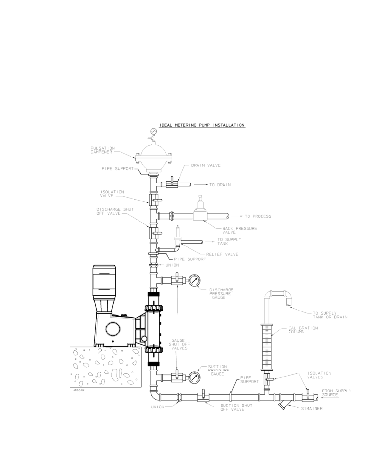
Figure 3, sample system
8
configuration
Page 9
6. Equipment Startup
6.1 Fastener Inspection
All pump fasteners should be checked prior to pump operation, and occasionally
during use. This would include reagent head mounting bolts, motor mounting bolts,
and the hardware tha t secures the pump to its foundation. Most hardware can be
checked simply to ensure it is not loose. However, utilize the following values when
checking reagent head bolt torque:
Model
DM7
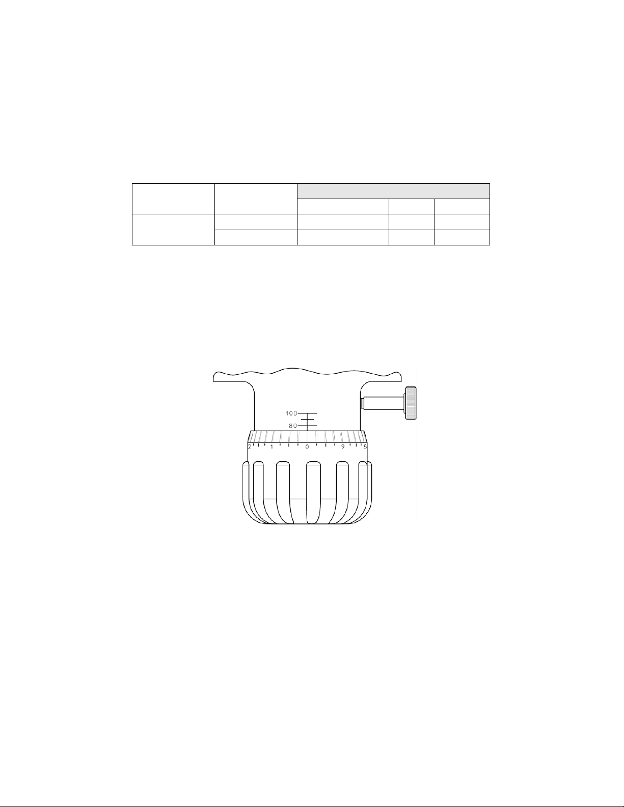
6.2 Output Adjustment
All GLM® DM7 pumps have a hand wheel for manual stroke adjustment. The hand
wheel can be adjusted to any point from 0 to 100%. This value represents the stroke
length setting and therefore the flow rate of the pump relative to its maximum output.
1. Turn the red lock screw counterclockwise to release the stroke lock. Making
adjustments without releasing the lock may damage the mechanism.
Material
Plastic (8) M10 * 1.5
Metal
(8) M10 * 1.5
Reagent Head Bolt Torque
# Bolts and size N-m In. - Lbs
8.5
8.5
75
75
Figure 4, stroke adjustment knob and scale
2. Adjust the hand wheel to the d esired ou tput.
a. The stroke barrel indicates s troke len gth in 20 % incr ements.
b. The hand wheel indicates stro ke len gth in 0 .25% inc rements.
For example, to set the pump to 75% stroke length, (starting from the factory default
setting of 0%) turn the hand wheel clockwise until the 60% indicator on the stroke
barrel is aligned with the edge of the knob at the “0” position on the knob scale.
Continue the clockwise rotation until the hand wheel indicator passes zero again (this
is 70%) and comes to 5, this is 75%. Refer to Figure 4.
3. Turn the lock screw clockwise to lock the stroke adjustment into position.
Adjustments can be made while the pump is at rest or operating, although
adjustments are easier to make while the pump is in operation.
9
Page 10
6.3 Oil Fill and Maintenance
Pulsafeeder Part No.
Description
Container Size
NP980010-001
PULSALube EP Gear Oil
500 ml
NP980010-002
PULSALube EP Gear Oil
1
liter
NP980010-003
PULSALube EP Gear Oil
2.5
liter
NP980010-004
PULSALube EP Gear Oil
18
liter
6.3.1 Oil Capacities
It is recommended that adequate supplies of PULSALube oil be on hand for periodic
changes and emergency requirements. The approximate amounts of oil required to fill
the GLM
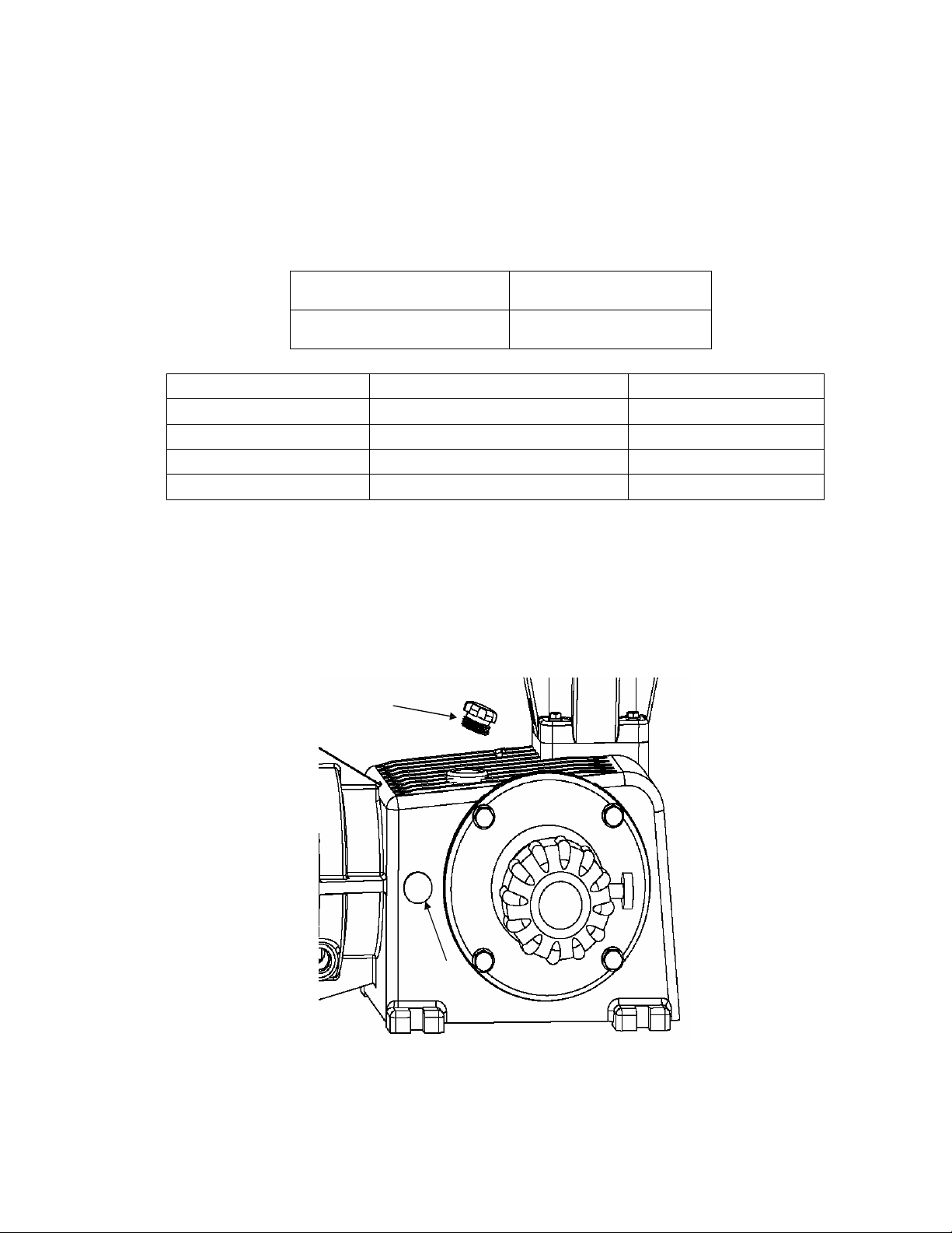
6.3.2 Gearbox Oil Fill
Fill the gearbox with oil by removing the threaded oil fill cap on the top of the pump. Fill
with the proper oil (PULSALube EP Gear Oil) to the upper edge of the sight glass on the
side of the pump. Replace the cover or controller. Replace the oil fill cap. See figure 5.
Note that during operation, the oil should be visible at the middle of the sight glass.
®
DM7 pump to specified levels are:
Pump Capacity
PULSALube EP Gear Oil
Figure 5, oil filler cap and sight glass
Gearbox, Model DM7
2,500 ml (2.6 Qt)
10
Page 11

6.3.3 Oil Changes
The recommended oil change intervals are dependent upon the operating environment and level of
pump usage, classified as follows:
Normal service: Clean/dry atmosphere, an ambient operating temperature of 00 C to 400 C
0
F to 104
(32
0
F) and up to 2,000 annual operating hours.
Severe Service: Humid atmosphere, an ambient operating temperature below 00 C (320 F) or
0
above 40
C (1040 F), and over 2,000 annual operating hours.
The recommended eccentric oil change interval is two (2) years for normal service and one (1)
year for severe service. The procedure is as follows:
1. Disconnect the power source to the drive motor
2. Relieve all pressure from the piping system.
3. Remove the fill plug from the top of the pump gearbox.
4. Drain the oil by removing the drain plug on the bottom of the gearbox, opposite the stroke
adjustment knob.
5. Replace the drain plug.
6. Fill the eccentric box with PulsaLube oil as described under Gearbox Oil Fill
.
7. Replace the fill plug and double check that the drain plug is secure.
6.4 Priming the Reagent Head
1. When handling process liquids, follow all applicable personal and facility safety guidelines.
2. Ensure that the pump is ready for operation and that all process connections are secure.
3. Open the suction and discharge line shutoff valves.
4. If the piping system design and the storage tank are such that the product flows due to
gravity through the pump, reduce the discharge pressure and the system will self prime when
the pump is started. In the event the discharge line contains a significant amount of
pressurized air or other gas, it may be necessary to lower the discharge pressure to enable
the pump to self-prime.
5. If the installation involves a suction lift, it may be necessary to prime the reagent head and
suction line.
Operate the pump as in step 4 above, many times the pump will be capable of
self priming. If it does not begin to pump, remove the discharge valve assembly. Carefully fill
the reagent head through the discharge valve port with process (or compatible) liquid, and
then reinstall the check valve.
11
Page 12

6. Start the pump at the zero stroke length setting and slowly increase the setting to 100 to
prime the pump. If this does not work, it will be necessary to fill the suction line.
7. Filling of the suction line will necessitate the use of a foot valve or similar device at the end
of the suction line so that liquid can be maintained above the reservoir level. Remove the
suction valve assembly, fill the line, replace the suction valve, then remove the discharge
valve assembly and fill the reagent head as described in Step (3) above. The pump will now
self-prime when started up per step (4) above. Use appropriate precautions if handling
process fluid. Ensuree that any other fluid used for priming is compatible with the product
that will be pumped.
Figure 6, process
flow
12
Page 13

6.5 Calibration
Figure 7, sample flow calibration curve
All metering pumps must be calibrated to accurately specify stroke length settings for
required flow rates.
A typical calibration chart is shown above. Although output is linear with respect to stroke
length setting, an increase in discharge pressure decreases output uniformly, describing a
series of parallel lines, one for each pressure (only two are shown).
The theoretical output flow rate at atmospheric discharge pressure is based on the
displacement of the diaphragm, stroke length and the stroking rate of the pump. With
increasing discharge pressure there
is a
corresponding decrease in output flow. Pumps are
rated for a certain flow at a rated pressure (check nameplate). Whenever possible, calibration
should be performed under actual process conditions (i.e., the same or a similar process liquid
at system operating pressure).
To construct a calibration chart, measure the flow rate several times at three or more stroke
settings (i.e., 25, 50, 75, and 100), plot these values on linear graph paper, and draw a best-fit
line through the points. For stable conditions, this line should predict settings to attain required
outputs.
All users are encouraged to test the flow rate of their pump once installed in their
system, to ensure best accuracy and reliable operation.
13
Page 14

7. Maintenance
BEFORE PERFORMING ANY MAINTENANCE REQUIRING REAGENT HEAD OR VALVE (WET END)
DISASSEMBLY, BE SURE TO RELIEVE PRESSURE FROM THE PIPING SYSTEM AND, WHERE
HAZARDOUS PROCESS MATERIALS ARE INVOLVED
AND THE ENVIRONMENT BY CLEANING AND CHEMICALLY NEUTRALIZING AS APPROPRIATE
WEAR PROTECTIVE CLOTHING AND EQUIPMENT AS APPROPRIATE.
Accurate records from the early stages of pump operation will indicate the type and levels of
required maintenance. A preventative maintenance program based on such records will
minimize operational problems. It is not possible to forecast the lives of wetted parts such as
diaphragms and check valves. Since corrosion rates and operational conditions affect functional
material life, each metering pump must be considered according to its particular service
conditions.
The GLM
maintenance program. It is recommended that KOPkits and PULSALube EP Gear Oil be
kept available at all times.
IF THE DIAPHRAGM HAS FAILED, PROCESS FLUID MAY HAVE CONTAMINATED THE PUMP
ECCENTRIC HOUSING
DIAPHRAGM WOULD PASS THROUGH THE BOTTOM DRAIN HOLE
CARE
®
KOPkit will contain all replacement parts normally used in a preventative
.
, RENDER THE PUMP SAFE TO PERSONNEL
.
(ALTHOUGH NORMALLY, ANY PROCESS FLUID BEHIND A FAILED
). HANDLE WITH APPROPRIATE
14
Page 15
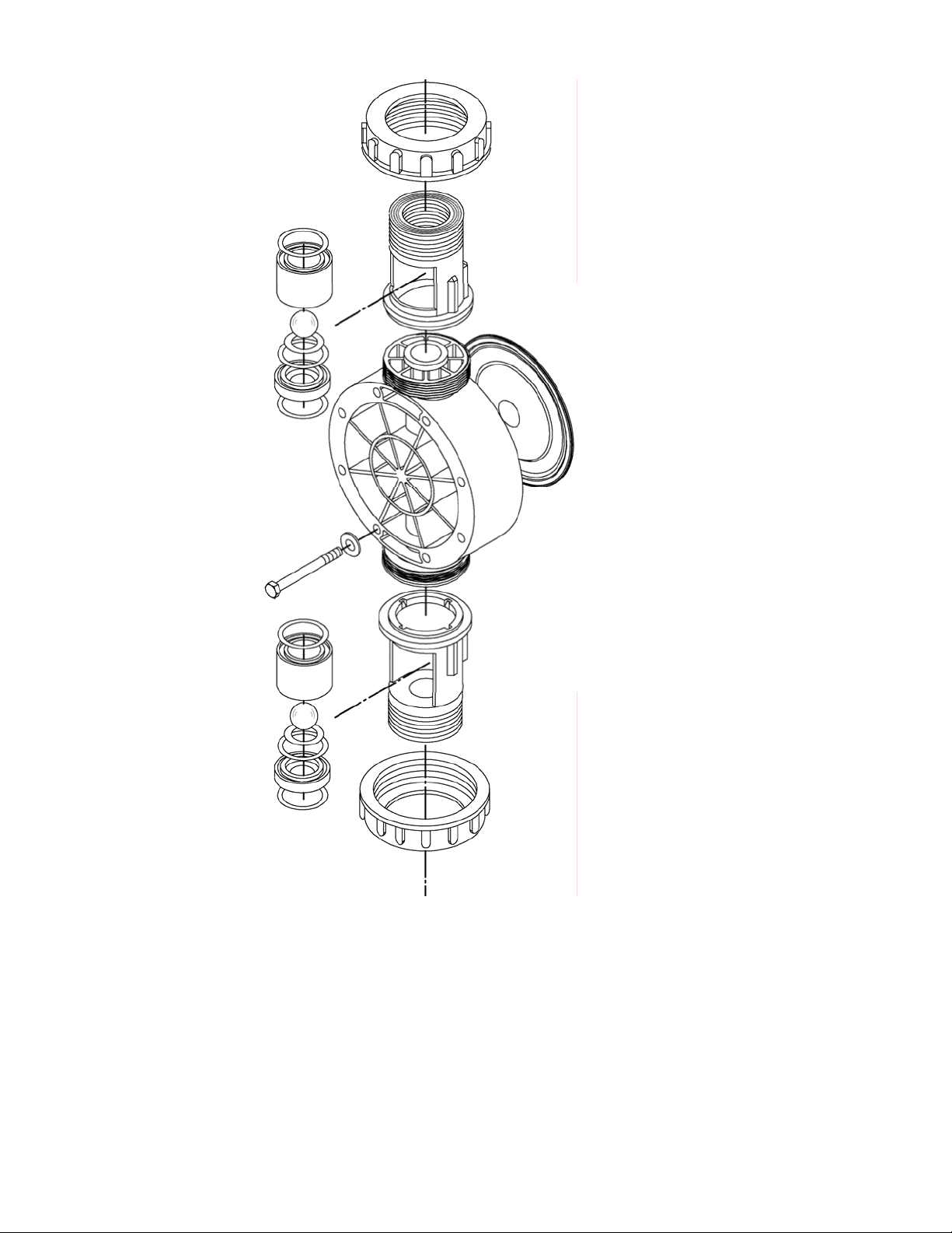
Figure 8, wet end
components
GLM® DM7 diaphragms do not have a specific cycle life; however, the accumulation of foreign
material or debris sufficient to deform the diaphragm can eventually cause failure. Failure can
also occur as a result of system over pressure or chemical attack. Periodic diaphragm
inspection and replacement are recommended. Each user should perform regular inspections
to determine the replacement
interval that
is appropriate to their system conditions.
15
Page 16
7.1 Diaphragm Removal & Reinstallation
1. Adjust the stroke setting to 0% and disconnect the power source to the drive motor.
2. Relieve all pressure from the piping system.
Take all precautions described under the WARNINGS on page 14, Section 7 to prevent
environmental damage and exposure of personnel to hazardous materials.
3. Close the inlet and outlet shutoff valves.
4. Place a pan underneath the pump head adaptor to catch any liquid leakage.
5. Note the orientation of the existing check valve components. Loosen the union nuts
holding the check valves and piping to the reagent head. Remove the check valve
assemblies, drain and rinse them, and set them aside in a safe place. Unscrew the union
nuts completely from the regent head.
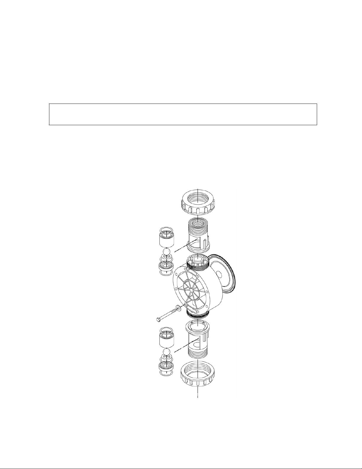
Figure 9, wet end
components
16
Page 17
6. Remove all but one top reagent head bolt. Product will leak out between the pump head
adaptor and reagent head as the bolts are loosened.
7. Remove the final bolt and rinse or clean the reagent head with an appropriate material.
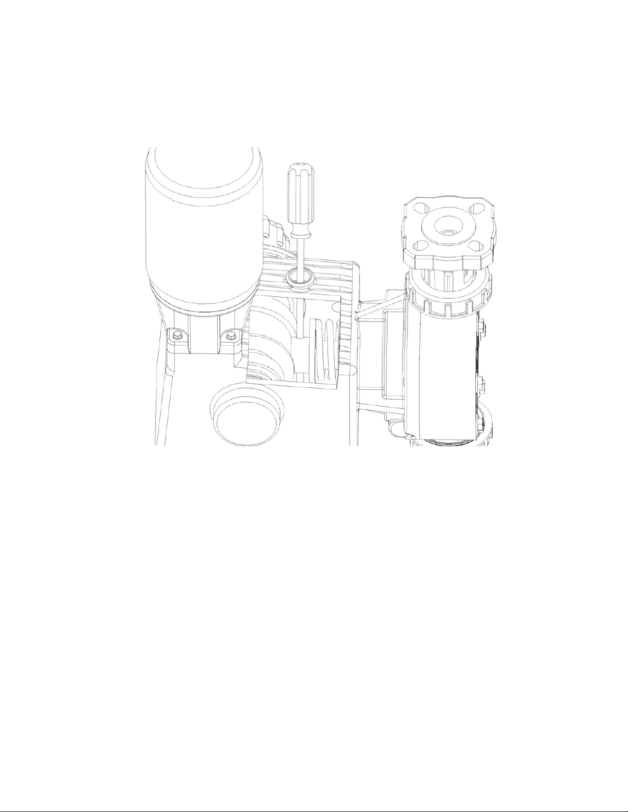
8. Insert a screwdriver or similar tool through the oil fill hole and into the hole provided in the
pushrod, this will keep the pushrod from turning as the diaphragm is removed. Note that
depending
to access the hole.
on pushrod
position, you may have to rotate the motor coupling or the diaphragm
Figure 10, securing
pushrod
9. Remove the diaphragm by turning it counter-clockwise.
10. Inspect the diaphragm. The diaphragm must be replaced if it is cracked, separated, or
obviously damaged.
11. Install the diaphragm.
a) Ensure that the critical sealing areas of diaphragm, reagent head, and pump head are
clean and free of debris.
b) Lubricate the elastomer side of the diaphragm liberally, where it is in contact against
the pump head and deflection plate. Use a silicone grease or silicone-based o-ring
lubricant.
c) Coat the threads and the end of the pushrod with an anti-seize paste or lubricant.
17
Page 18
12. Thread the diaphragm (clockwise) fully onto the shaft.
When reinstalling a used diaphragm it is not necessary to maintain the previous orientation
relative to the reagent head or pump head hole pattern.
13. Remove the screwdriver from the oil fill hole and replace the cap.
14. Install the reagent head bolts and tighten in an alternating pattern to ensure an even seating
force. Torque to the values recommended in Section 6.1.
15. Reassemble the piping connections and check valves to the reagent head, using care
to orient all check valve parts properly (refer to figures 9 and 12).
16. Re-prime the pump following the procedure outlined in Section 6.3.
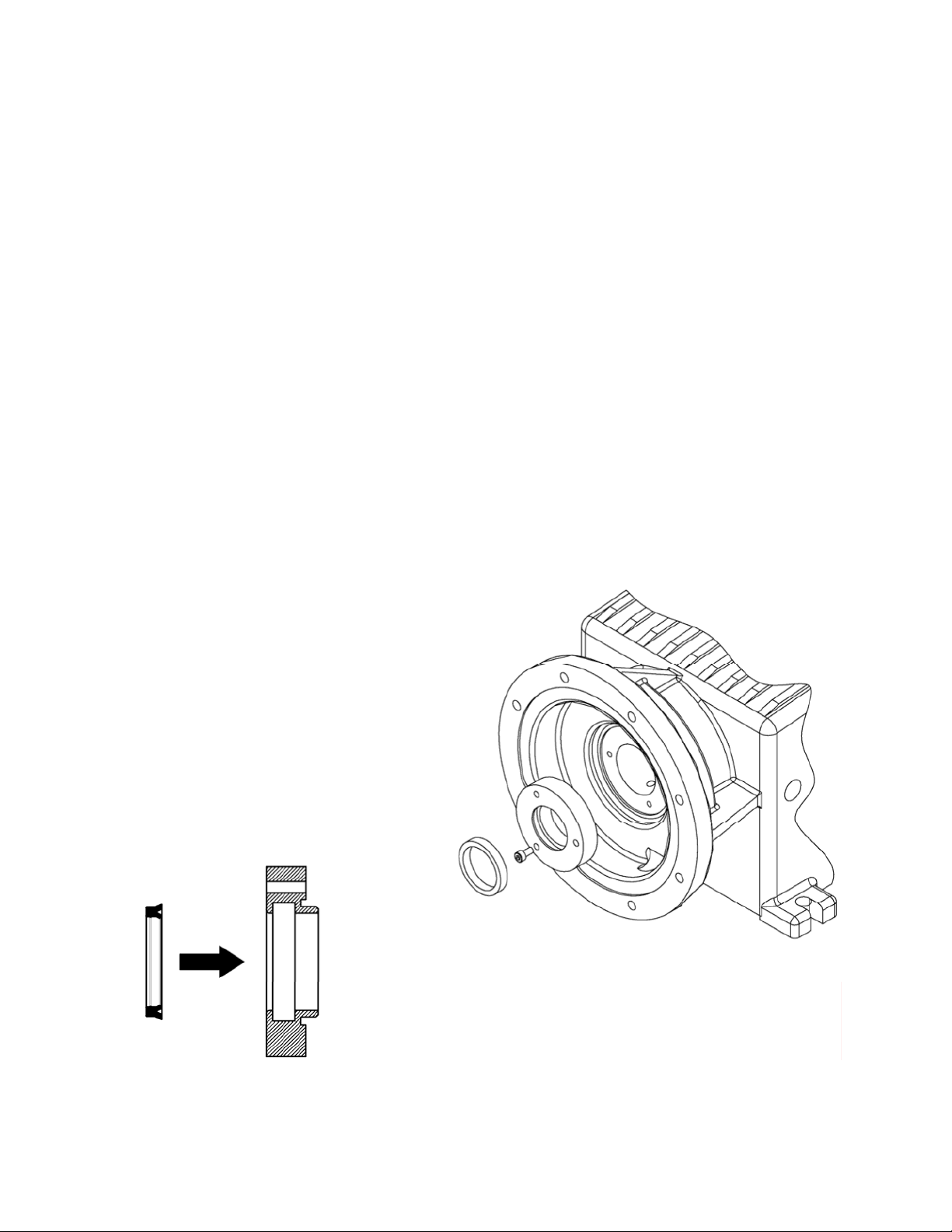
7.2 Diaphragm Shaft Seal
While the diaphragm is removed, inspect the shaft seal located in the pump head. If there is
evidence of damage or wear and/or oil leakage, the seal should be replaced.
1. Remove the three retainer screws and the seal retainer.
2. Pry the old seal out of the retainer.
3. Ensure the surfaces of the retainer are clean and clean of debris, scratches, or burrs.
4. Insert the new seal into the retainer by hand, do not use tools to prevent damage to the seal.
5. Inspect the piston shaft and remove any scratches, burrs, or surface corrosion or damage.
6. Lubricate the shaft with a small amount of pump oil.
7. Slide the seal and retainer back into position and secure with the three screws.
Figure 11, piston shaft seal replacement
18
Page 19

7.3 Check Valves
Most fluid metering problems are related to check valves. Problems usually stem from solids
accumulation between valve and seat, corrosion of seating surfaces, erosion, or physical
damage due to wear or the presence of foreign objects.
The valve incorporates a ball, guide, and seat. Flow in the unchecked direction lifts the ball
off the seat, allowing liquid to pass through the guide. Reverse flow forces the ball down,
sealing it against the sharp edge of the seat. The guide permits the ball to rotate but
restricts vertical and lateral movement in order to minimize “slip” or reverse flow. Ball
rotation prolongs life by distributing wear over the entire surface of the ball. Since ball return
is by gravity, the valve must be in the vertical position in order to function properly. Parts are
sealed by “O”-rings.
GLM® DM7 xpumps utilize a multi-part check valve assembly, secured to the reagent head
with a union nut clamping arrangement (plastic construction) or a tie-bar arrangement (metal
construction).
Figure 12, check valves
DM7
19
Page 20
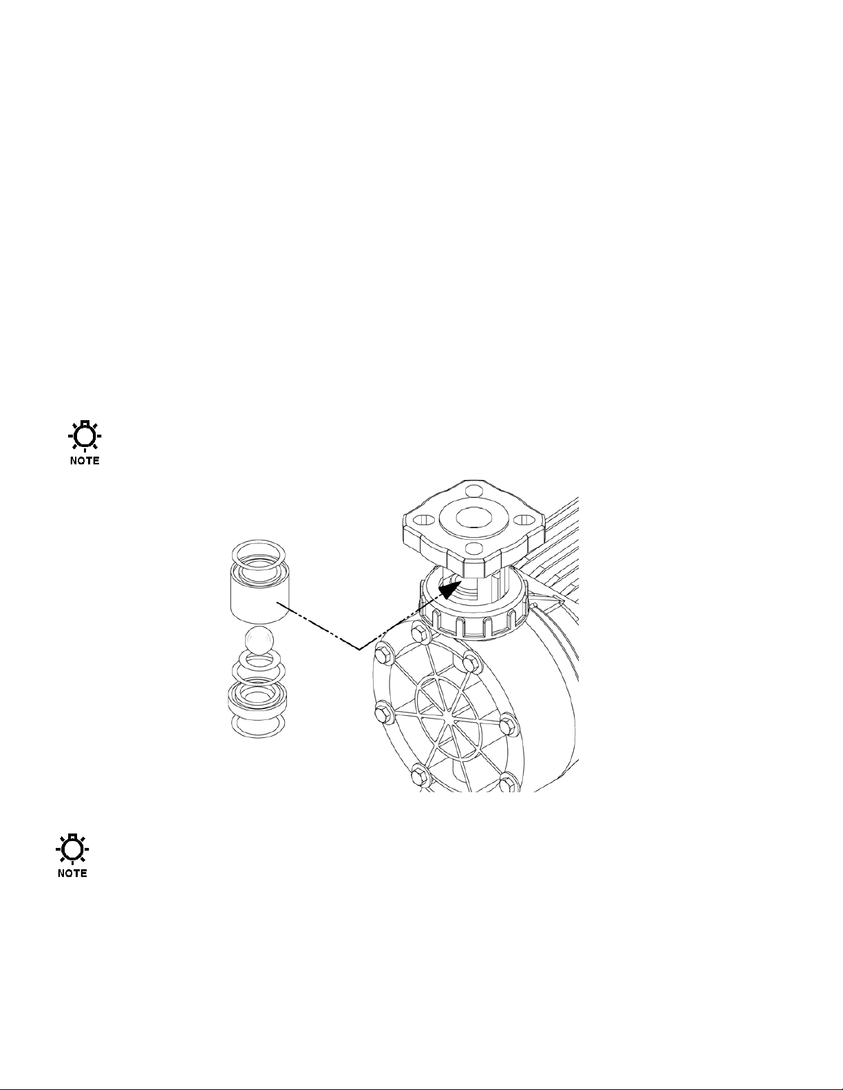
7.4 Check Valve Removal & Reinstallation, Plastic Union-Nut type
1. Disconnect the power source to the drive motor.
2. Relieve all pressure from the piping system, and take all precautions necessary
to prevent contamination to the environment and personnel exposure to
hazardous materials.
3. Close the inlet and outlet shutoff valves.
4. Loosen the union nuts that hold the check valves in place. It is not necessary to
completely remove the nut.
5. Push the check valve assembly out of the front by inserting your finger or a tool into the
clearance hole at the back of the holder. Note carefully the position of the component
parts, to assist in re- assembly. Be aware that product may leak out as the check valve
parts are removed.
6. Replace both valve assemblies onto the pump, taking care to ensure they are oriented
correctly, with the balls above the seats, and the seats oriented with the o-ring seat facing up
and the chamfered edge down.
The check assemblies must be pushed into the holder until they stop against the
back surface. Replace parts with new as required. Sealing o-rings should generally
be replaced even if the check components are re-used.
Figure 13, union-nut type check
valve
Inserting the check valve assembly into the pump in the wrong directiom, or having the
check seat upside down, will prevent proper seals at the o-rings, decrease pump
performance, and can cause damage to the diaphragm. Each union nut should be
tightened only until the o-ring seal makes good contact.
7. Carefully make sure that the check asse mblies are i n proper position , and tighten the union nuts .
8. Retighten any unio ns, flanges, or other proces s connections t hat may hav e been loosened p reviously.
20
Page 21
7.5 Check Valve Removal and Reinstallation, Metal Tie-Bar type
1. Disconnect the power source to the drive motor.
2. Relieve all pressure from the piping system.
3. Take all precautions necessary to prevent contamination to the environment and personnel
exposure to hazardous materials.
4. Close the inlet and outlet shutoff valves.
5. Loosen the suction valve tie-bar bolts (4) and spring the suction piping slightly away from
the head, allowing liquid to drain. It may be necessary to loosen a union or flange.
6. Remove the suction check valve assembly by sliding it towards you, holding it together as a unit.
Note carefully the position of the component parts, to assist in re-assembly.
7. Loosen the discharge valve tie-bar bolts (4) and spring the discharge piping slightly away
from the head, allowing liquid to drain. It may be necessary to loosen a union or flange.
8. Remove the discharge check valve assem bly by slidi ng it towards y ou, holding it together as a uni t.
Note carefully the position of the component parts, to assist in re-assembly.
9. Disassemble both valves and check components for wear or damage. The seats should
have a sharp edge and be free from dents or nicks. Hold a ball firmly against the seat in
front of a bright light and inspect for fit, observation of light between the ball and seat is
cause for replacement.
10. Reassemble both valves using new parts as required. Sealing o-rings should always be
replaced.
11. Replace both valve assemblies onto the pump, taking care to ensure they are oriented
correctly, with the balls above the seats, and the seats oriented with the sharp edge up and
the chamfered edge down.
Inserting the check valve assembly into the pump in the wrong direction, or having the
check seat upside down, will prevent proper seals at the o-rings, decrease pump
performance, and can cause damage to the diaphragm.
12. Carefully make sure that the check assemblies are in proper position, and tighten the
four tie-bar bolts, using a star pattern, to a torque of 6 Ft-lbs (8 N-m).
13. Retighten any unions, flanges, or other process connections that may have been loosened
previously.
21
Page 22

Figure 14, Check valves, metal construction
22
Page 23

7.6 Motor Removal & Reinstallation
1. Disconnect the power source to the drive motor.
2. Disconnect the motor wiring from the motor.
3. Remove the four bolts retaining the motor to the motor adaptor.
Lift the motor upwards away from the
4. Apply an anti-seize paste or lubricant to all bolts, setscrews, and keys
before reassembling..
5. Reinstall the motor in the reverse from removal.
6. Insert and tighten the four bolts removed in step 3.
7. Reconnect the motor wiring to the motor.
8. Connect power to the drive motor.
Motor rotation must be wired for CW rotation,
as viewed from the top of the motor, as noted
pump.
by the arrow on the top of the pump housing.
Figure 15, motor
mounting
23
Page 24

8. Replacement Parts
8.1 KOPkit Program
GLM® DM7 KOPkits contain all replacement parts normally used in a preventative
maintenance program. (PULSAlube oil is also available separately for preventative
maintenance programs. Refer to Section 6 – Equipment Startup). There is a specific
KOPkit for every GLM
All GLM
®
pumps have the KOPkit number identified on the pump nameplate and Pulsafeeder
order documents. KOPkits can also be selected from the technical data sheet shipped with
the pump or by a Pulsafeeder representative. A list of the GLM
found on the next page. The kit is identified by the model number of the pump, the wetted end
material, and the process connection thread type. For models with tie-bar type check valves,
the appropriate components (check valve balls, seats, and o-rings) are supplied instead of the
cartridges pictured.
®
pump model. Each KOPkit is vacuum-packed for extended storage.
®
KOPkit numbers can also be
Figure 16, KOPkit
parts
8.2 Ordering KOPkits or Parts
When ordering replacement parts always specify:
•
Pump model and serial number (from pump nameplate), e.g., Model No. (DM7) with Serial
No. F406365-3.
•
Part number and description from the GLM® parts list. Include the three-character suffix.
(Note: GLM
NP170001-THY or
®
part numbers begin either with the letters NP, or the letter W, e.g.,
W210221-001.)
24
Page 25

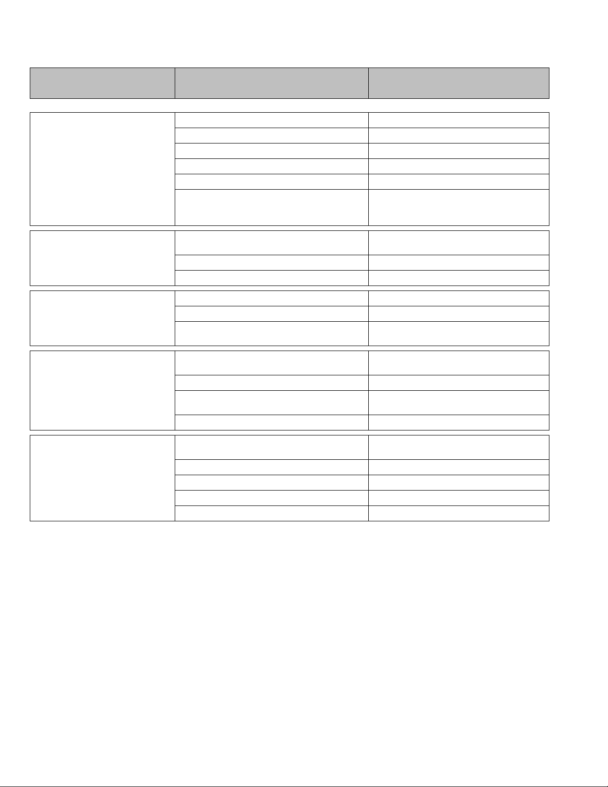
8.3 KOPkit numbers by model:
Pump Model
Wetted Material
Connection Type
KOPkit number
Position
Sample
Specifies
Options
1 – 4
DM
Size/Flow
DM GLM
for DM7)
O-rings - Ceramic Ball Valves
DM7
DM7
NOTES:
(1) DM1 through 6 models are covered in a separate publication
(2) Polypropylene KOPkits are identical as only balls and insert o-rings are supplied
Polypropylene NPT / ISO / FLG
31 6
KD7P
NPT KD7A
9. Model Number Identification
5 Y Motor
Frame and
Size
6 P Wetted
Materials
7 P Connection P 1.5” FNPT with 1.5” ANSI/DIN flange ring as standard
3 3PH 220/380V (and 460V) MOTOR IEC Frame, TEFC
[50/60 Hz]
Y NO MOTOR - IEC frame (IEC71 for DMC1-6, IEC90 standard
A 316L SS Liquid End - PTFE Diaphragm and PTFE O-rings –
316SS Ball Valves
F PVDF/Viton - PVDF Liquid End - PTFE Diaphragm and Viton®
O-rings - Ceramic Ball Valves
P PP/Viton - PP Liquid End - PTFE Diaphragm and Viton®
25
Page 26

10. Troubleshooting
DIFFICULTY PROBABLE CAUSE REMEDY
Faulty power source Check power source
Blown fuse, circuit breaker overload Replace - eliminate
Pump does not start
Broken wire Locate and repair
Wired improperly Check diagram
Process piping blockage Open valves, clear other obstructions
No delivery
Low delivery
Motor not running
Check power source. Check wiring
diagram (see above)
Supply tank empty Fill tank
Lines clogged Clean and flush
Closed line valves Open valves
Ball check valves held open with solids Clean - inspect, flush with clear fluid
Vapor lock, cavitation Increase suction pressure
Prime lost Re-prime, check for leak
Strainer clogged
Remove and clean. Replace screen if
necessary
Stroke adjustment set at zero Increase stroke lenth setting
Check voltages, frequency, wiring and
Motor speed too low
terminal connections. Check
nameplate vs. Specificatio n s
Check valves worn or dirty Clean, replace if damaged
Calibration system error Evaluate and correct
Lower viscosity by increasi ng produc t
Product viscosity too high
temperature or dilution. Increase
pump and/or piiping size
Product cavitating Increase suction pressure
Delivery gradually drops
Check valve leakage Clean, replace if damaged
Leak in suction line Locate and correct
Strainer fouled Clean or replace screen
Product change Check viscosity and other variables
Supply tank vent plugged Unplug vent
26
Page 27
DIFFICULTY PROBABLE CAUSE REMEDY
Leak in suction line Locate and correct
Product cavitating Increase suction pressure
Entrained air or gas in product Consult factory for suggested venting
Delivery erratic
Motor speed erratic Check voltage and frequency
Fouled check valves Clean, replace if necessary
Increase discharge pressure to obtain a
Inadequate backpressure
minimum pressure difference of 5 psi from
suction to discharge
Delivery higher than rated
Noisy gearing, knocking
Piping noisy
Motor overheats
Suction pressure higher than discharge
pressure
Back pressure valve set too low Increase setting
Vack pressure valve leaks Repair, clean or replace
Discharge pressure too high Reduce pressure
Water hammer Install pulsation dampener
Low oil level
Pipe size too small
Pip runs too long Install pulsation dampener in line
Pulsation sampener inoperative or flooded
No surge chamber or dampener used Install pulsation dampener
Pump overloaded
High or low voltage Check power source
Loose wire Trace and correct
Incorrect motor wiring Verify and correct
Oil level low Check and add as cecessary
Install backpressure valve or consult
factory for piping recommendations
Examine sight glass on side of pump, add or
replace oil as required.
Increase size of piping - install pulsation
dampener
Refill with air or insert gas. Inspect and replace
diaphragm and recharge
Check operating conditions against pump
design. Verify discharge pressure
27
Page 28

11. Piping Accessories
Pressure Relief Valves
Pressure relief valves are designed to protect chemical feed systems from damage that may be
caused by defective equipment or a blockage in the discharge line. These valves function to limit
the pressure downstream of the pump. Field adjust the pressure relief valve to operate when the
discharge pressure exceeds operating pressure by 10-15%. Pressure relief valve should always
be adjusted to a setting below the maximum rated pressure of the pump. No potentially
restrictive components, such as a valve,
the PRV.
Diaphragm Backpressure Valve
A diaphragm backpressure valve creates constant back pressure. A PTFE or PTFE-faced
diaphragm offers maximum chemical protection and service life, and seals spring and
bonnet from product.
Be sure to install with fluid flow in direction of arrow on valve body.
Pulsation Dampener
A pulsation dampener is a pneumatically charged diaphragm-type chamber that intermittently
stores hydraulic energy. Used on the inlet, it can improve NPSHA (Net Positive Suction Head
available) characteristics of the suction piping system. On the discharge line it will reduce
discharge pressure and pulsating flow variations.
should be
installed between the pump discharge and
28
Page 29
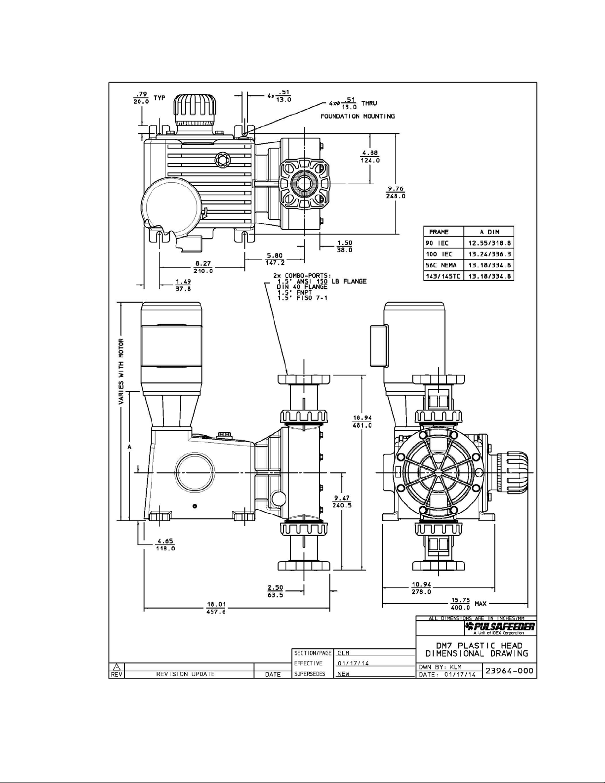
12. Dimensional Drawings
29
Page 30

30 31
Page 31
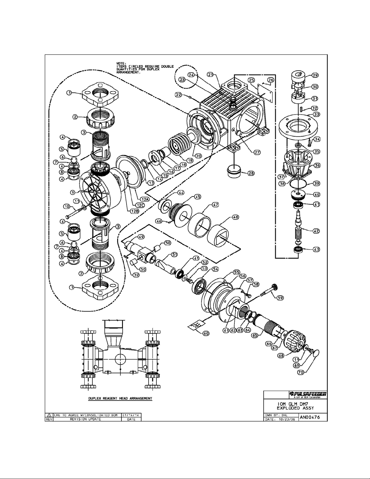
13. Parts Diagrams and Parts Lists
Page 32

32
Page 33
PULSA GLM®
A unit of IDEX Corporation
MECHANICAL DI AP HRAGM METERING PUMP
Bulletin #: IOM-GLM-DM7-001
2883 Brighton Henrietta Town Line Road
Rochester NY 14623
+1 (585) 292-8000
www.pulsa.com
pulsa@idexcorp.com
 Loading...