

Page 1
PULSA GLM®
Bulletin #: IOM-GLM-1303-A
Installation, Operation &
Maintenance Instruction
Models: GLM M1 – 6
MECHANICAL DI AP HRAGM
METERING PUMP
Page 2

ii
Pulsafeeder Factory Service Poli cy
Pulsafeeder’s Factory Service Policy is maintained on its website. Please source this document at
this URL:
http://www.pulsa.com/downloads/pdf/Pulsafeeder%20EPO%20Limited%20Warranty%20Statement.pdf
Safety Considerations:
1. Read and understand all related instructions and documentation before attempting to install or
maintain this equipment.
2. Observe all special instructions, notes, and cautions.
3. Act with care and exercise good common sense and judgment during all installation,
adjustment, and maintenance procedures.
4. Ensure that all safety and work procedures and standards that are applicable to your company
and facility are followed during the installation, maintenance, and operation of this equipment.
Copyright ©2013 Pulsafeeder, Inc. All rights reserved.
Information in this document is subject to change without notice. No part of this publication may be
reproduced, stored in a retrieval system or transmitted in any form or any means electronic or
mechanical, including photocopying and recording for any purpose other than the purchaser’s
personal use without the written permission of Pulsafeeder, Inc.
Page 3

iii
Table of Contents
1. EQUIPMENT INSPECTION ....................................................................................................................... 1
2. INSTALLATION ...................................................................................................................................... 1
2.1 Location ................................................................................................................................... 1
2.2 Motor ........................................................................................................................................ 1
2.3 Piping System ......................................................................................................................... 2
2.4 Suction Pressure Requirements ........................................................................................... 3
2.5 Discharge Pressure Requirements ....................................................................................... 4
3. EQUIPMENT STARTUP .......................................................................................................................... 5
3.1 Fastener Inspection ................................................................................................................ 5
3.2 Output Adjustment ................................................................................................................. 5
3.3 Priming the Reagent Head ..................................................................................................... 6
3.4 Calibration ............................................................................................................................... 7
4. MAINTENANCE ..................................................................................................................................... 7
4.1 Lubrication .............................................................................................................................. 8
4.2 Wet End Removal, Inspection, & Reinstallation .................................................................. 9
4.3 Check Valves ........................................................................................................................... 11
4.4 Motor Removal & Reinstallation ........................................................................................... 13
4.5 Pump Head Removal .............................................................................................................. 14
5. REPLACEMENT PARTS ......................................................................................................................... 15
5.1 KOPkit Program ...................................................................................................................... 15
5.2 Ordering KOPkits or Parts ..................................................................................................... 15
5.3 KOPkit numbers by model:.................................................................................................... 16
6. TROUBLESHOOTING ............................................................................................................................. 17
7. PIPING ACCESSORIES .......................................................................................................................... 19
8. DIMENSIONAL DRAWING ....................................................................................................................... 20
9. PARTS DIAGRAM S AN D ITEM NUMBERS ................................................................................................. 22-23
Page 4

Page 5
1. Equipment Inspection
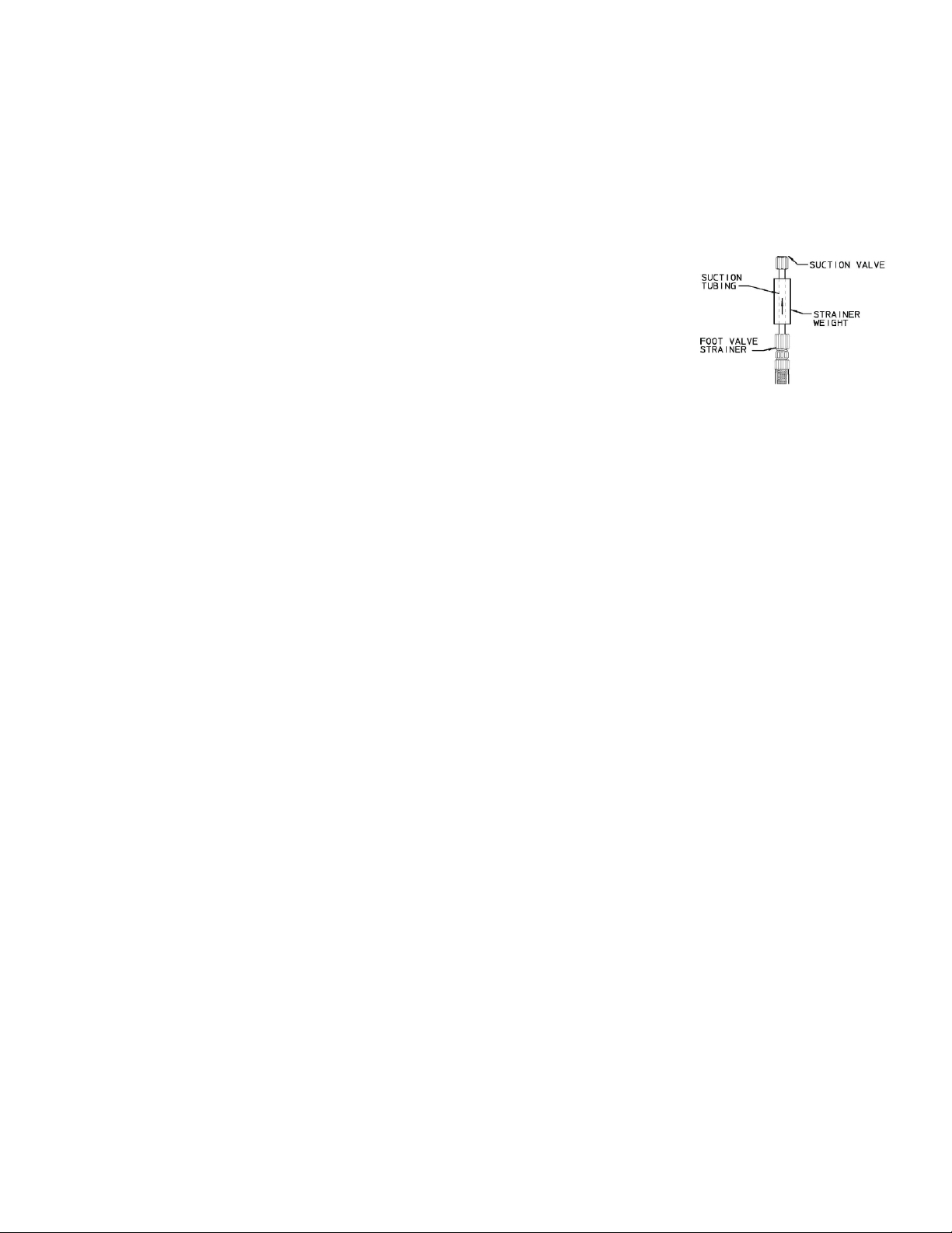
Figure 1: Foot Valve Kit
Check all equipment for completeness against the order and for any evidence of shipping damage.
Shortages or damage must be reported immediately to the carrier and your authorized representative or
distributor of PULSA GLM
Included Items:
• PULSA GLM® Metering Pump with Motor Adaptor
Optional Items:
• Motor (pre-installed at the factory)
• Foot Valve Kit (provided on PULSA GLM® models M1 and M2 only).
®
pumps.
2. Installation
2.1 Location
When selecting an installation site or designing a chemical feed system, plan for operation and routine
maintenance. Provide 1M (3.25FT) of space around the pump for this purpose.
PULSA GLM
sunlight, and precipitation (i.e., under shelter). The ambient temperature must be between 0° C (32° F)
and 40° C (104° F). If necessary add environmental controls.
®
pumps are designed to operate in an environment where the pump is protected from direct
The pump must be rigidly bolted to a solid and flat foundation to minimize vibration and prevent
loosening of the connections. The pump must be level within 5° to assure proper ch eck valve operation.
2.2 Motor
The PULSA GLM® is typically shipped with the motor pre-installed. It must be wired in accordance with
local and national requirements by a qualified electrician. Please refer to the motor nameplate for further
manufacture specific information.
If the PULSA GLM® was purchased less motor, please refer to section 5.4 Motor Installation for further
instructions.
1
Page 6
2.3 Piping System
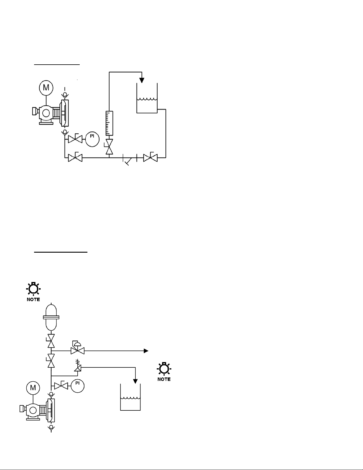
Figure 3: Discharge P&ID
Figure 2: Suction P&ID
Attention to piping detail will assure an easy startup and long life of your GLM
Suction Piping
Isolation Valve and Unions: Isolation valves allow
the system to be isolated from the process fluid to
facilitate safe servicing. They also aid in the operation
of Calibration columns. Valves should include good
visible indications of open/closed condition. Unions
assist with installation and maintenance. Valves that
integrate union fittings are ideal.
Strainer: Successful installations always include a
strainer on the suction side of the pump to exclude
material that can cause the check valves to
malfunction or the diaphragm to rupture. Select the
material, size and mesh to be compatible with the fluid
type, intended flow rate and service interval. A 100
mesh screen is generally recommended.
Calibration Column (Optional): Used to calibrate pump performance. Include an isolation valve and
vent line back to the supply tank to facilitate safe operation.
Pressure Gage (Optional): A pressure gage should be included on the suction side of the pump when
the suction pressure of the system is unknown or variable. The gage is also a good indicator of Strainer
maintenance status.
Discharge Piping
®
. Please follow these guidelines:
Discharge Pressure Gage: Install a pressure gage no less than 2 pipe diameters from the threaded
fitting on the discharge valve. A discharge pressure gage is critical to confirming proper operation of the
pump and setting the pressure relief and back pressure valves.
IMPORTANT: DO NOT Install an elbow directly into the discharge valve threaded fitting as it
will create excessive back pressure that can lead to premature diaphragm failure.
Pressure Relief Valve: Install a Pressure Relief Valve as close
to the pump as possible. Using the leg of a T fitting for this
purpose is acceptable (with the normal discharge taking the
straight path and the relief flow taking the leg). The relief
pressure must be set at or below the rated pressure indicated
on the pumps nameplate.
NOTE: Failure to install and properly set a Pressure
Relief Valve can lead to damage of the Pumps drive
mechanism that will not be covered under warranty.
Back Pressure Valve: Install a Back Pressure Valve to
generate a consistent Back Pressure to the pump for accurate
operation and to prevent siphoning.
Pulsation Dampener: Reciprocating diaphragm metering
pumps only discharge fluid for ½ of a pump cycle. A Pulsation
Dampener will smooth the associated flow/pressure variation to
the down stream process.
2
Page 7

Piping System Recommendations
1. When making the threaded joint to the valve cap assembly, use a sealing compound chemically
compatible with the process material (for example Loctite® 8551 [Loctite is a registered Trade Mark of
Henkel Corporation] for water service). Do not use sealing tape. The valve cap should be tightened by
hand and then tightened 1 additional turn (i.e., 360 degrees) with the aid of an adjustable wrench.
2. Both new and existing piping should be cleaned, preferably by flushing with a clean liquid (compatible
with process material) and blown out with air, prior to connection to the pump.
Note - Debris from manufacturing the pip ing system (e.g., PVC shavings, TFE Tape, dirt, etc.)
can be unknowingly assembled inside the pipe. When fluid is introduced this material can be
transferred to the pump and prevent proper check valve operation. T h is is a common startup
issue.
3. Piping weight must not be supported by valve housings or other portions of the reagent head, as the
resulting stresses can cause leaks. Valve loads must not exceed 13.5 N-M (10 FT-LBF) moment or
22N (5 LBF) in any direction. When temperature variations are expected provide for thermal
expansion and contraction of piping components so that force and/or moments are controlled within
the allowable range.
4. When making process connections, ensure that pipe joint cement and thread sealants do not run into
the check valve assemblies as this will inhibit valve operation. This is a common startup issue.
2.4 Suction Pressure Requirements
Although PULSA GLM® metering pumps have some suction lift capability, a flooded suction (i.e., suction
pressure higher than atmospheric pressure) is preferable whenever possible. The pump should be
located as close as possible to the suction side reservoir or fluid supply source.
For fluid with a vapor pressure of 0.35 Bar (5 psia) or less (at operating temperature) the wet suction lift
capability is approximately 3 meters (10 feet). If this requirement is not met, the pump will not provide
reliable, accurate flow. In suction lift conditions, the use of a foot valve is recommended at the lowest
point of the pickup tube or pipe. Pumps operating under suction lift conditions may require some liquid
priming before they will operate reliably.
3
Page 8
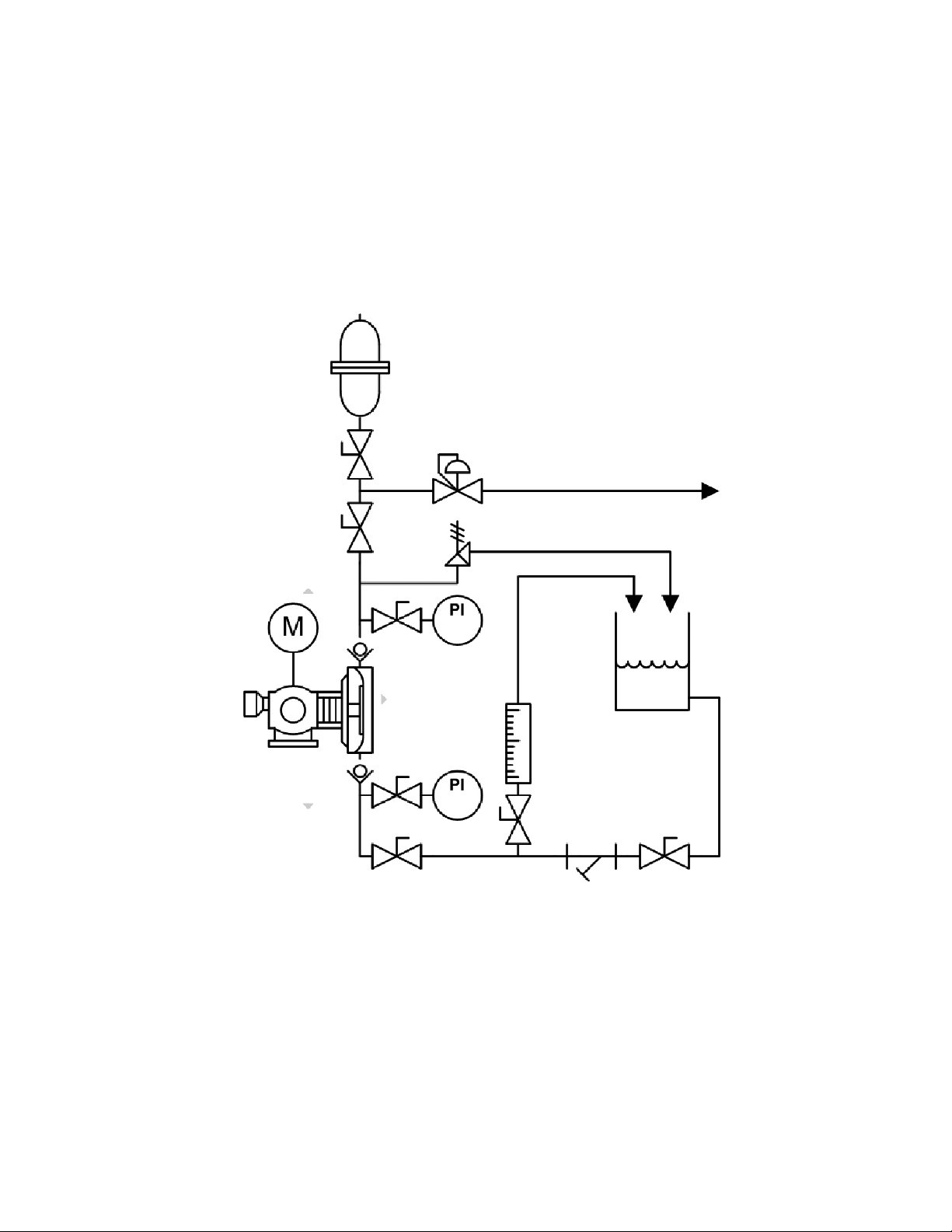
2.5 Discharge Pressure Requirements
All PULSA GLM® metering pumps are designed for continuous service at the rated discharge pressure.
If the system suction pressure exceeds the discharge pressure (a condition sometimes described as
“pumping downhill”), flow will be generated in addition to that generated by the pump. This results in a
reduction in accuracy and loss of control over the metering process. To prevent this flow-through
condition, the discharge pressure must exceed the suction pressure by at least 0.35 BAR (5 PSI). This
can be achieved, where necessary, by the installation of a backpressure valve in the discharge line.
Conditions where the actual discharge pressure exceeds the pumps rating are to be avoided as they will
cause damage to the pump components.
Figure 4: PULSA GLM P&ID
4
Page 9
3. Equipment Startup
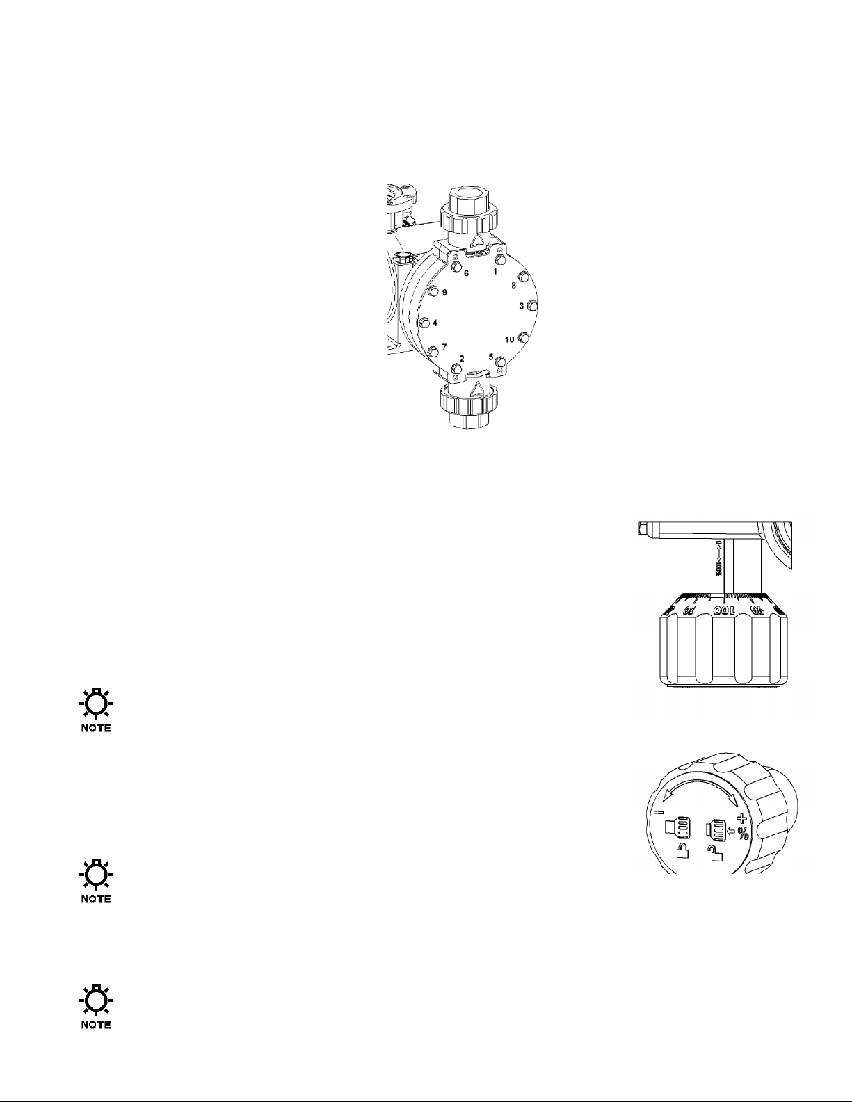
Figure 5: Reagent Head Bolt tightening
Figure 6: Stroke Adjustment Knob
3.1 Fastener Inspection
All pump fasteners should be checked prior to pump operation, and occasionally during use. This would
include reagent head mounting bolts, motor mounting bolts, and the hardware that secures the pump to
its foundation.
The motor and reagent head mounting bolts should be torqued to 4.5 N-M (40 IN-LBF). Bolts should be
tightened in a star pattern across the head to assure uniform clamping of the diaphragm (see
recommended tightening sequence in above diagram).
3.2 Output Adjustm ent
All PULSA GLM® pumps have a knob for manual stroke length
adjustment. The knob can be adjusted to any value between 0 to 100%.
The stroke length setting is directly proportional the flow rate of the pump.
1. Push the knob in towards the gearbox to release the locking
mechanism.
Note - Making adjustments without releasing the lock may damage
the locking mechanism.
2. Adjust the knob to the desired output.
a) Read the setting directly from the knob marking where it aligns with
the stroke barrel.
b) The knob is labeled in 10% increments with 1% graduation marks.
The knob will lock in 0.5% increments.
Note – Do not adjust the knob beyond the indicated range.
For example, to set the pump to 75% stroke length (starting from the factory default setting of 0%)
push the knob in (to unlock) and turn it approximately ¾ turn clockwise until he 75% indicator is
aligned with the line on the stroke adjustment barrel.
3. Release the knob to re-engage the locking mechanism.
Note – Stroke adjustments should be made while pump is operating.
5
Page 10

3.3 Priming the Reagent Head
Figure 7: System Configured for Self-Priming
CLOSED
OPEN
1. When handling process liquids, follow all applicable personal and facility safety guidelines.
2. Ensure that the pump is ready for operation and that all process connections are secure.
3. Open the suction and discharge line shutoff valves.
4. If the piping system design and the storage tank are such that the product flows due to gravity through
the pump, reduce the discharge pressure and the system will self prime when the pump is started. In
the event the discharge line contains a significant amount of pressurized air or other gas, it may be
necessary to lower the discharge pressure to enable the pump to self-prime.
5. If the installation involves a suction lift, it may be necessary to prime the reagent head and suction line.
Operate the pump as in step 4 above - many times the pump will be capable of self priming. If it does
not begin to pump fluid, remove the discharge valve assembly. Carefully fill the reagent head through
the discharge valve port with process (or compatible) liquid, and then reinstall the check valve.
6. Start the pump at the 0% stroke length setting and slowly increase the setting to 100% to prime the
pump. If this does not work, it will be necessary to fill the suction line.
7. Filling of the suction line will necessitate the use of a foot valve or similar device at the end of the
suction line so that liquid can be maintained above the reservoir level. Remove the suction valve
assembly, fill the line with fluid, replace the suction valve, then remove the discharge valve assembly
and fill the reagent head as described in Step 5 above. The pump will now self-prime when started up
per step 6 above.
Use appropriate precautions if handling process fluid. Ensure that any other fluid used for
priming is compatible with the product that will be pumped.
6
Page 11

3.4 Calibration
All metering pumps must be calibrated to accurately correlate stroke length settings to measured flow
rates.
A typical calibration chart is shown above. Although output is linear with respect to the stroke length
setting, an increase in discharge pressure decreases output uniformly, describing a series of parallel
lines, one for each pressure (only two are shown).
Figure 8: Sample Flow Calibration Curve
The theoretical output flow rate at atmospheric discharge pressure is based on the displacement of the
diaphragm, stroke length and the stroking rate of the pump. With increasing discharge pressure there is
a corresponding decrease in output flow. Pumps are rated for a certain flow at a rated pressure (check
nameplate). Whenever possible, calibration should be performed under actual process conditions (i.e.,
the same or a similar process liquid at system operating pressure).
To construct a calibration chart, measure the flow rate several times at three or more stroke settings
(e.g., 25, 50, 75, and 100), plot these values on linear graph paper, and draw a best-fit line through the
points. For stable conditions, this line should predict settings to attain required outputs.
Note - All users are encouraged to test the flow rate of their pump once installed in their system,
to ensure best accuracy and reliable operation.
4. Maintenance
BEFORE PERFORMING ANY MAINTENANCE REQUIRING REAGENT HEAD OR VALVE (WET END)
DISASSEMBLY
PROCESS MATERIALS ARE INVOLVED
BY CLEANING AND CHEMICALLY NEUTRALIZING AS APPROPRIATE
EQUIPMENT AS APPROPRIATE
Accurate records from the early stages of pump operation will indicate the type and levels of required
maintenance. A preventative maintenance program based on such records will minimize operational
problems. It is not possible to forecast the lives of wetted parts such as diaphragms and check valves.
Since corrosion rates and operational conditions affect functional material life, each metering pump must
be considered according to its particular service conditions.
The PULSA GLM
program. It is recommended that KOPkits and PULSAlube 9M be kept available at all times.
, BE SURE TO RELIEVE PRESSURE FROM THE PIPING SYSTEM AND, WHERE HAZARDOUS
®
KOPkit will contain all replacement parts normally used in a preventative maintenance
, RENDER THE PUMP SAFE TO PERSONNE L AND THE ENVIRONMENT
. WEAR PROTECTIVE CLOTHING AND
.
7
Page 12

4.1 Lubrication
PULSA GLM® pumps have an oil bath reservoir that is pre-filled with 250mL of PULSAlube 9M at the
factory. For optimum pump performance under normal conditions, the PULSAlube 9M should be replaced
every 3,000 hours. For severe service in non-temperature controlled and/or dirty environments the
PULSAlube 9M should be replaced every 1,500 hours.
1. Disconnect the power source to the drive motor, and relieve all pressure from the piping system.
2. Remove the Vent/Fill cap on top of the Gear Box under the motor adaptor lip.
3. Locate the Gear Box drain plug at the bottom of the Gear Box under the Stroke Adjustment Knob (see
Figure below).
4. While holding the Gear Box over a catch reservoir, remove the drain plug (be sure to retain the sealing
o-ring on the plug).
5. Replace the Drain Plug and sealing o-ring.
6. Fill the Gear Box with 250mL of PULSAlube 9M so that the level indicates in the center of the sight
glass on the side.
7. Replace the Vent/Fill cap and sealing o-ring.
Figure 9: Gear Box Fill/Drain Points
Figure 10: Gear Box PULSAlube 9M Normal Level
8
Page 13

Qty.
DM1 and
DM2
DM3 and
DM4
DM5 and
DM6
1
Discharge Connection
Assembly
1 1 1
2
Discharge Valve Assembly
1 1 1
3
O-ring 2 2
2
4
Reagent Head
1 1 1
5
Diaphragm
1 1 1
6
Front Cover Plate
1 1 1
7
Hex Head Bolt
8
10
12
8
Flat Washer
8
10
12
9
Suction Check Valve
Assembly
1 1 1
10
Suction Connection Assembly
1 1 1
11
Hex Nuts
8
10
n/a
4.2 Wet End Removal, Inspection, & Reinstallation
IF THE DIAPHRAGM HAS FAILED, PROCESS FLUID MAY HAVE CONTAMINATED OTHER PARTS OF THE PUMP
INCLUDING THE DRIVE COMPONENTS
DIAPHRAGM WOULD PASS THROUGH THE BOTTOM DRAIN HOLE
(ALTHOUGH NORMALLY, ANY PROCESS FLUID BEHIND A FAILED
). HANDLE WITH APPROPRIATE CARE.
Figure 11: Wet End Components
Item Description
PULSA GLM
material or debris sufficient to deform the diaphragm can eventually cause failure. Failure can also
occur as a result of system over pressure or chemical attack. Periodic diaphragm inspection and
replacement are recommended. Each user should perform regular inspections to determine the
replacement interval that is appropriate to their system conditions.
®
diaphragms do not have a specific cycle life; however, the accumulation of foreign
9
Page 14

4.2.1 Diaphragm Removal & Reinst al lat ion
1. Adjust the stroke setting to 50% and disconnect the power source to the drive motor.
2. Relieve all pressure from the piping system.
3. Close the inlet and outlet shutoff valves.
4. Place a pan underneath the pump head adaptor to catch any liquid leakage.
5. Disconnect piping to the reagent head and drain any process liquid, following all recommended
material safety precautions.
6. Remove all but one top reagent head bolt. Product will leak out between the pump head adaptor and
reagent head as the bolts are loosened. Use prescribed engineering controls to prevent exposure and
accidental discharge to environment.
7. Tilt the head and pour out any liquids retained by the check valves into a suitable container, continuing
to follow safety precautions as appropriate.
8. Remove the final bolt and rinse or clean the reagent head with an appropriate material.
9. Remove the diaphragm by turning it counter-clockwise.
10. Inspect the diaphragm. The diaphragm must be replaced if it is cracked, separated, or obviously
damaged.
11. Install the diaphragm.
a) Ensure that the critical sealing areas of diaphragm,
reagent head, and pump head are clean and free of
debris.
12. Thread the diaphragm (clockwise) fully onto the shaft.
13. Install the reagent head bolts and tighten in an
alternating pattern to ensure an even seating force.
Torque bolts to 4.5 N-M (40 IN-LBF).
14. Re-prime the pump following the procedure outlined in
Section 3.3
10
Figure 12: Reagent Head Assembly Cross Section
Page 15

4.3 Check Valves
Direction of
Flow (UP)
4.3.1 General Description
The valve incorporates a ball, guide, and seat. Flow in the unchecked direction lifts the ball off the
seat, allowing liquid to pass through the guide. Reverse flow forces the ball down, sealing it against
the bevel edge of the seat and o-ring. The guide permits the ball to rotate but restricts vertical and
lateral movement in order to minimize “slip” or reverse flow. Ball rotation prolongs life by distributing
wear over the entire surface of the ball. Since ball return is by gravity, the valve must be in the vertical
position in order to function properly. Parts are sealed by o-rings.
Figure 13: Cartridge Check Valve
4.3.2 Check Valve Removal & Reinstallation, Cartridge type
Valving that is of the cartridge design is intended to be replaced as an assembly.
1. Disconnect and Lockout the power supply to the drive motor.
2. Relieve all pressure from the piping system.
3. Take all precautions necessary to prevent contamination to the environment and personnel exposure
to hazardous materials.
4. Close the inlet and outlet shutoff valves.
5. Disconnect the suction piping at the suction shut-off valve union by releasing the union retaining nut.
Caution – Process fluid may drain from the Piping. Take necessary precautions.
6. Disconnect the discharge piping at the discharge shut-off valve union by releasing the union retaining
nut.
Caution – Process fluid may drain from the piping. Take necessary precautions.
7. Loosen and remove the suction valve cartridge retaining nut and drain any liquid from the reagent
head.
8. Disconnect the discharge piping at the installed union near the discharge port.
9. Loosen and remove the discharge valve cartridge slowly to drain any trapped liquid.
10. Reinstall both new valve assemblies. For both the suction and discharge the valve orientation should
be as shown in Figure 13.
Take care to assure o-rings are fully seated in groves and are not displaced during assembly. A pinched
o-ring can cause the assembly to leak. If necessary use a compatible o-ring retaining compound.
11
Page 16

4.3.3 Check Valve Removal & Reinstal lation, Tie-bar type
Figure 14: Tie Bar Style Metal
1. Disconnect and Lockout the power supply to the drive motor.
2. Relieve all pressure from the piping system.
3. Take all precautions necessary to prevent contamination to the
environment and personnel exposure to hazardous materials.
4. Close the inlet and outlet shutoff valves.
5. Loosen the suction valve tie-bar bolts (4) and spring the suction
piping slightly away from the head, allowing liquid to drain. It
may be necessary to loosen a union or flange.
Caution – Process fluid may drain from the Piping. Take
necessary precautions.
6. Remove the suction check valve assembly by sliding it towards
you, holding it together as a unit. Note carefully the position of
the component parts, to assist in re-assembly.
7. Loosen the discharge valve tie-bar bolts (4) and spring the
discharge piping slightly away from the head, allowing liquid to
drain. It may be necessary to loosen a union or flange.
Caution – Process fluid may drain from the Piping. Take necessary precautions.
8. Remove the discharge check valve assembly by sliding it towards you, holding it
together as a unit. Note carefully the position of the component parts, to assist in
re-assembly.
9. Disassemble both valves and check components for wear or damage. The seats
should have a sharp edge and be free from dents or nicks. Hold a ball firmly
against the seat in front of a bright light and inspect for fit. Observation of light
between the ball and seat is cause for replacement.
10. Reassemble both valves using new parts as required. Sealing o-rings should
always be replaced.
11. Replace both valve assemblies onto the pump, taking care to ensure they are
oriented correctly, with the balls above the seats, and the seats oriented with the sharp edge up and
the chamfered edge down.
Inserting the check valve assmbly into the pump in the wrong
directiom, or having the check seat upside down, will prevent proper
seals at the o-rings, decrease pump performance, and can cause
damage to the diaphragm.
Valves
Figure 15: Metal
Valve
12. Carefully make sure that the check assemblies are in proper position, and tighten the four tie-bar bolts,
using a star pattern, to a torque of 6 Ft-lbs (8 N-m).
13. Retighten any unions, flanges, or other process connections that may have been loosened previously.
12
Page 17

4.4 Motor Removal & Reinstallation
Removal
1. Disconnect and Lockout the power supply to the drive motor.
2. Disconnect the motor wiring from the motor.
3. Remove the four bolts retaining the motor to the motor adaptor.
4. The motor shaft is keyed to a plastic coupling that slides into a splined bore in the pump input shaft.
Lift the motor straight up to slide the motor shaft coupling out of the pump input shaft.
Installation
1. Install the plastic coupling over the motor key onto the motor shaft. For
the 56C frame motor the coupling should be even with the end of the
shaft. For the 71 frame motor the coupling should be installed over the
shaft up to the collar (the end of the shaft will be slightly recessed into
the coupling).
Note: Assure the motor key is
fully covered by the motor
coupling.
2. Reinstall the motor by sliding the motor vertically into the pump
input shaft.
3. Align the motor bolts holes to the motor adaptor plate.
4. Install the 4 motor retaining bolts. Torque to 4.5 N-M (40 INLBF).
5. Connect the motor wiring to the motor in accordance with Local,
National and Motor Manufacturer requirements.
6. Restore power.
Figure 16: Motor Mounting
The PULSA GLM® is designed to operate with any Motor rotation direction (clockwise or counter
clockwise).
13
Page 18

Warning – Stored energy
4.5 Pump Head Removal
The PULSA GLM® includes a Pump Head that clamps the diaphragm to the Reagent Head. In the event
of diaphragm failure process fluid can come into contact with this part (it includes a drain hole to prevent
fluid accumulation). Over time, it is possible for this part to suffer some level of deterioration and need
replacement.
1. Disconnect and Lockout the power supply to the drive motor.
2. Relieve all pressure from the piping system.
3. Take all precautions necessary to prevent contamination to the environment and personnel exposure to
hazardous materials.
4. Close the inlet and outlet shutoff valves.
5. Remove the Valving, Reagent Head and Diaphragm as described in section 4.2.1.
6. Drain the oil from the pump.
7. Set the pump stroke setting to 100%.
8. Rotate the pump motor until the Cross Head (the part that the Diaphragm threads onto) is fully retracted
into the Gear Box.
9. Evenly loosen all (4) bolts that retain the Pump Head to the Gear Box.
release possible - use caution!
The pump head compresses a
large spring that is used to
return the diaphragm to its
retracted position. Special tools
may be required to reattach the
pump head.
10. Remove old pump head from front of Gear Box.
11. Orient replacement Pump Head with drain hole pointed down. Assure o-ring is in place on Gearbox side.
12. Ensure the bellows oil seal is seated on the end of the cross head as shown above.
13. Insert Spring Guide of Pump Head over Cross Head and into spring. Take care to assure spring does not
catch on tapered guide during installation.
14. Install the four retaining bolts. Tighten evenly. Torque to 6.75N-M (60IN-LBF).
15. Install Diaphragm, Reagent Head and Valving as defined in Section 4.2.1.
Figure 17: Pump Head
Retaining Bolt Removal
a.
b. Figure 18, Pump Head Cross Section and Bellows Seal
14
Page 19

5. Replacement Parts
5.1 KOPkit Program
PULSA GLM® KOPkits contain all replacement parts normally used in a preventative maintenance
program. (PULSAlube is also available separately for preventative maintenance programs. Refer to
Section 3 – Equipment Startup). There is a specific KOPkit for every PULSA GLM
Each KOPkit is vacuum-packed for extended storage. All PULSA GLM
identified on the pump nameplate and Pulsafeeder order documents. KOPkits can also be selected from
the technical data sheet shipped with the pump or by a Pulsafeeder representative. A list of the PULSA
GLM KOPkit numbers can also be found on the next page. The kit is identified by the model number of
the pump, the wetted end material, and the process connection thread type. For models with tie-bar type
check valves, the appropriate components (check valve balls, seats, and o-rings) are supplied instead of
the cartridges pictured.
5.2 Ordering KOPkits or Parts
When ordering replacement parts always specify:
• Pump model and serial number (from pump nameplate), e.g., Model No. (M2) with
Serial No. F406365-3.
®
®
pumps have the KOPkit number
pump model.
Figure 19: PULSA GLM® Nameplate
• Part number and description from the PULSA GLM
(Note: PULSA GLM part numbers begin either with the letters NP, or the letter W, e.g., NP170001THY or W210221-001.)
15
®
parts list. Include the three-character suffix.
Page 20

5.3 KOPkit numbers by model:
DM0
DM2
DM3
DM4
DM6
DM0
DM2
DM6
DM7 & DM7 Duplex
DM0
DM2
DM4
DM5
DM6
Pump Model
DM1
DM5
DM7 & DM7 Duplex
DM1
DM3
DM4
DM5
DM1
DM3
DM7 & DM7 Duplex
Wetted
Material
PP
PVDF
316SS
KOPkit
Number
KD0PX
KD1PX
KD2PX
KD3PX
KD4PX
KD5PX
KD6PX
KD7PX
KD0FX
KD1FX
KD2FX
KD3FX
KD4FX
KD5FX
KD6FX
KD7FX
KD0AX
KD1AX
KD2AX
KD3AX
KD4AX
KD5AX
KD6AX
KD7AX
16
Page 21

6. Troubleshooting
Difficulty
Probable Cause
Remedy
Pump motor does
Faulty power source.
Check power source.
Blown fuse, circuit breaker.
Replace - eliminate overload.
Broken wire.
Locate and repair.
Wired improperly.
Check diagram.
Process piping blockage.
Open valves, clear other obstructions.
Test by setting stroke to 0%.
No fluid delivery
Motor not running.
Check power source. Check wiring
diagram (see above).
Supply tank empty.
Fill tank.
Line clogged.
Clean and flush.
Closed in-line valve(s).
Open valve(s).
Ball check valves held open with
solids.
Clean – inspect, flush with clear fluid.
Vapor lock, cavitation.
Increase suction pressure.
Prime lost.
Re-prime, check for leak.
Strainer clogged.
Remove and clean. Replace screen if
necessary.
Stroke adjustment set at zero.
Increase stroke length setting.
Low fluid delivery
Motor speed too low.
Check voltages, frequency, wiring,
nameplate vs. Specifications.
Check valves worn or dirty.
Clean, replace if damaged.
Calibration system error.
Evaluate and correct.
Product viscosity too high.
Lower viscosity by increasing product
pump and/or piping size.
Product cavitating.
Increase suction pressure.
Delivery gradually
Check valve leakage.
Clean, replace if damaged.
Leak in suction line.
Locate and correct.
Strainer fouled.
Clean or replace screen.
Product change.
Check viscosity and other variables.
Supply tank vent plugged.
Unplug vent.
Delivery erratic.
Leak in suction line.
Locate and correct.
Product cavitating.
Increase suction pressure.
Entrained air or gas in product.
Consult factory for suggested venting.
Motor speed erratic.
Check voltage and frequency.
Fouled check valves.
Clean, replace if necessary.
Inadequate backpressure
Increase discharge pressure to obtain
psi from suction t o discharge.
Delivery higher than
discharge pressure.
factory for piping recommendations.
Back pressure valve set too low.
Increase setting.
Back pressure valve leaks.
Repair, clean, or replace.
Noisy gearing,
Discharge pressure too high.
Reduce pressure.
Water hammer.
Install pulsation dampener.
Stroke length at partial setting.
Some operating noise is characteristic
of lost motion pumps.
Low grease level.
Add or replace grease.
not start
drops.
rated.
Suction pressure higher than
and terminal connections. Check
temperature or dilution. Increase
a minimum pressure difference of 5
Install backpressure valve or consult
knocking
17
Page 22

Difficulty
Probable Cause
Remedy
Piping noisy.
Pipe size too small.
Increase size of piping - install
pulsation dampener.
Pipe runs too long.
Install pulsation dampener in line.
Pulsation dampener inoperative
or flooded.
Refill with air or inert gas. Inspect and
replace diaphragm and recharge.
No surge chamber or dampener
used.
Install pulsation dampeners.
Motor overheats.
Pump overloaded.
Check operating conditions against
pump design. Verify discharge
pressure.
High or low voltage.
Check power source.
Loose wire.
Trace and correct.
Incorrect motor wiring.
Verify and correct.
18
Page 23

7. Piping Accessories
Pressure Relief Valves
Pressure relief valves are designed to protect chemical feed systems from damage that may be caused by
defective equipment or a blockage in the discharge line. These valves function to limit the pressure
downstream of the pump. Field adjust the pressure relief valve to operate when the discharge pressure
exceeds operating pressure by 10-15%. Pressure relief valve should always be adjusted to a setting
below the maximum rated pressure of the pump. No potentially restrictive components, such as a valve,
should be installed between the pump discharge and the PRV.
Diaphragm Backpressure Valve
A diaphragm style backpressure valve creates constant back pressure. A PTFE or PTFE-faced
diaphragm offers maximum chemical protection and service life, and seals spring and bonnet from
product.
Be sure to install with fluid flow in direction of arrow on valve body.
Pulsation Dampener
A pulsation dampener is a pneumatically charged diaphragm-type chamber that intermittently stores
hydraulic energy. Used on the inlet, it can improve NPSHA (Net Positive Suction Head Available)
characteristics of the suction piping system. On the discharge line it will reduce discharge pressure peaks
and pulsating flow variations.
19
Page 24

8. Dimensional Drawing
Dimension table in mm / inches
Dimensions are with standard IEC 71 B14 frame motor
20
Page 25

Model
DM1 &
DM2
DM3 &
DM4
DM5 &
DM6
Dimension
A B C D E F
71 160.0 / 6.3
95.5 / 3.8 300.0 / 11.8 94.5 / 3.7 85.5 / 3.4 37.0 / 1.5
56C 196.0 / 7.7
71 160.0 / 6.3
95.5 / 3.8 315.0 / 12.4 94.5 / 3.7 95.8 / 3.7 37.0 / 1.5
56C 196.0 / 7.7
71 160.0 / 6.3
95.5 / 3.8 325 / 12.8 94.5 / 3.7 99.3 / 3.9 37.0 / 1.5
56C 196.0 / 7.7
Model
DM1 &
DM2
DM3 &
DM4
DM5 &
DM6
71
56C
71
56C
71
56C
Dimension
G H J K L M
340.0 /
13.4
420.0 /
16.5
340.0 /
13.4
420.0 /
16.5
340.0 /
13.4
420.0 /
16.5
170.0 /
6.7
175.0 /
6.9
170.0 /
6.7
175.0 /
6.9
170.0 /
6.7
175.0 /
6.9
79.0 /
3.1
79.0 /
3.1
79.0 /
3.1
91.5 /
3.6
91.5 /
3.6
91.5 /
3.6
NPT /
BSPT
103.0 /
4.1
150.0 /
5.9
172.0 /
6.8
TUBING
131.0 /
5.2
N/A
N/A
NPT /
BSPT
206.0 / 8.1
300.0 /
11.8
344.0 /
13.5
TUBING
262.0 /
10.3
N/A
N/A
21
Page 26

9. Parts Diagrams and Item Numbers
2
CROSSHEAD
1
GL120001-STL
6
PUMP HEAD
1
GL150001-000
GL150002-000
GL150003-000
12E
ORING SEAT (P&F)
2
W049855-VTN
NP440109-VTN
NP440110-VTN
Item
Number
1 GEARBOX 1 GL010001-ALU
3 RETURN SPRING 1 GL430001-000
4 GASKET 1 GL440002-NTR
5 NUT -- NP991217-188 (8) NP991217-188 (12) NA
7 BELLOWS O-RING 1
7A BELLOWS SEAL 1 GL450001-000
8 PMP HEAD BOLT 4
9 DIAPHRAGM 1 GL170001-000 GL170002-000 GL170003-000
10
11
12 VALVE ASSY (P&F) 2
12A VALVE GUIDE (P&F) 2 GL310001-PVD GL310005-PVD GL310002-PVD GL310004-PVD
12B VALVE SEAT (P&F) 2 GL330001-PVD GL330005-000 GL330002-PVD GL330004-PVD
12C BALL (P&F) 2 L1000400-ALA W032580-ALA W041935-ALA W034581-ALA
12D VALVE SEALS (P&F) 6 NP440018-VTN W078200-VTN NP440027-VTN NP440031-VTN
Description
REAGENT HEAD (P)
REAGENT HEAD (F) GL160001-PVD GL160002-PVD GL160003-PVD NA
REAGENT HEAD (A) GL160004-316 GL160005-316 GL160006-316
BACKUP SEAL(P&F) 2
BACKUP SEAL(A) NA NOT APPLICABLE
QTY /
PUMP
1
Part Number
(DM1)
GL160001-FPP GL160002-FPP GL160003-FPP
NP440123-VTN
GL87XLFVCA-XXXX GL87XLFVCC-XXXX
NOT APPLICABLE
Part Number
(DM2)
Part Number
(DM3)
GL440001-NTR
GL990007-STL
NP440136-VTN
GL87XLFVEE-XXXX
Part Number
(DM4)
Part Number
(DM5)
NP440144-VTN
GL87XLFVFJ-XXXX
Part Number
(DM6)
22
Page 27

Item
12B
VALVE SEAT (A)
2
GL330006-316
GL330007-316
GL330008-316
GL330010-316
VALVE CAP (PB)
GL300002-FPP
GL300003-FPP
GL300004-FPP
25
GASKET
1
NP440141-NTR
29
GASKET
1
NP440014-NTR
35
STROKE KNOB
1
GL260001-000
39
RETAINING RING
1
GL995002-STL
41
ECC SHAFT
1
GL070001-001
GL070001-003
GL070001-004
GL070001-006
44
INNER GASKET
1
NP440152-NTR
Number
12 VALVE ASSY (A) 2
12A VALVE GUIDE (A) 2 GL310006-316 GL310007-316 GL310008-316 GL310010-316
12C BALL (A) 2 W046646-316 W032580-316 W041935-316 W034581-316
12D VALVE SEALS (A) 6 NP440018-TFE NP440018-TFE NP440027-TFE NP440031-TFE
12E ORING SEAT (A) NA
Description
QTY /
PUMP
Part Number
(DM1)
GL87XAATCA-XXXX GL87XAATCC -XXXX
Part Number
(DM2)
Part Number
(DM3)
GL87XAATEE-XXXX GL87XAATFJ-XXXX
NOT APPLICABLE
Part Number
(DM4)
Part Number
(DM5)
Part Number
(DM6)
13
14
15 PLATE (P&F ONLY) 1 GL140011-STL GL140012-STL GL140013-STL
16 RH BOLT -- GL990001-188 (8) GL990001-188 (10) GL990001-188 (12)
17 RH WASHER -- NP991017-188 (8) NP991017-188 (10) NP991017-188 (12)
18 OIL SIGHT GLASS 1 GL994001-000
19 OIL PLUG 2 GL030002-STL
20 SMALL BEARING 2 GL400002-000
21 WORM SHAFT 1 GL060004* GL060002*
22 UPPER BEARING 1 GL400003-000
23 RETAINING RING 1 GL995001-STL
24 COUPLING 1 GL410001-071
26 MOTOR ADAPTOR 1 GL490001-ALU
27 MOTOR SEAL 1 GL450002-000
28 ADAPTOR BOLTS 4 NP990024-188
30 BARREL 1 GL410002-000
31 STROKE LABEL 1 GL550002-000
31A OUTER ADJ SHAFT 1 GL410005-001 GL410005-003 GL410005-004 GL410005-006
32 INNER ADJ SHAFT 1 GL410004-001 GL410004-003 GL410004-004 GL410004-006
33 GASKET 1 NP440012-NTR
34 LOCK SPRING 1 GL430002-000
VALVE CAP (FB) GL300002-PVD GL300003-PVD GL300004-PVD NA
VALVE CAP (AB) GL300005-316 GL300006-316 GL300007-316
UNION NUT (P&F)
TIE BAR (A) GL360004-STL GL360005-STL GL360006-STL
2
2
GL360001-FPP GL360002-FPP GL360003-FPP
36 STROKE RETAINING RING 1 GL995003-STL
37 STROKE CAP 1 GL250002-PEB
38 GEAR 1 GL060001* GL060003*
40 INNER ECC BEARING 1 GL400005-000
40A OUTER ECC BEARING 1 GL400004-000
40B SPACER 2 GL470001-STL
42 GEAR KEY 1 GL420001-STL
42A LARGE BEARING 1 GL400006-000
43 TOLERANCE RING 1 NP470002-000
45 OUTER GASKET 1 NP440155-NTR
46 SIDE CAP 1 GL030001-ALU
47 SIDE CAP BOLTS 4 NP990415-188
48 COVER 1 NP530138-PVC
49 PUMP TAG 1 GL550001-000
50 TAG BOLTS 2 W771000-188
23
Page 28

Product
Repair Cost
Pumps and Pump Accessories – within 5 years of sale
date
Current List Price x .50 x Part Discount Multiplier
Controllers and Controller Accessories within 5 years of
With purchase order, $50 bench fee to evaluate. The $50 bench fee may be
1. Manufacturer’s Equipment Warranty
a. Pulsafeeder warrants all pumps and controllers of its manufacture to be free of defects in material or workmanship. Liability under this
policy extends for 24 months from date of shipment from the factory. The manufacturer’s liability is limited to repair or replacement of any
failed equipment or part which is proven defective in material or workmanship upon manufacturer’s examination. This warranty does not
include removal or installation costs and in no event shall the manufacturer’s liability exceed the selling price of such equipment or part.
b. The manufacturer disclaims all liability for damage to its products through improper installation, maintenance, use or attempts to operate
such products beyond their functional capacity, intentionally or otherwise, or any other unauthorized repair. The manufacturer is not
responsible for consequential or other damages, injuries or expense incurred through the use of its products.
c. The above warranty is in lieu of any other warranty, whether expressed or implied. The manufacturer makes no warranty of fitness or
merchantability. No agent of ours is authorized to provide any warranty other than the above.
2. Pulsafeeder’s Parts and Accessory Warranty
a. Pulsafeeder, Inc. warrants parts and accessories provided to be free of defects in material or workmanship. Unless otherwise noted
below, liability under this policy extends for 90 days from date of shipment from the factory when sold as service parts. (Replaceable
elastomeric parts are expendable and are not covered by any warranty either expressed or implied.)
b. The manufacturer’s liability is limited to repair or replacement of any failed equipment or part which is proven defective in material or
workmanship upon manufacturer’s examination. This warranty does not include removal or installation costs and in no event shall the
manufacturer’s liability exceed the selling price of such equipment or part.
c. The manufacturer disclaims all liability for damages to its products through improper instal l ation, maintenance, use or attempts to operate
such products beyond their functional capacity, intentionally or otherwise, or any unauthorized repair. The manufacturer is not
responsible for consequential or other damages, injuries or expense incurred through the use of its products.
d. The above warranty is in lieu of any other warranty, whether expressed or implied. The manufacturer makes no warranty of fitness or
merchantability. No agent of ours is authorized to provide any warranty other than the above.
3. Process for All Returned Goods
a. Please contact our Customer Service Department to request a RMA (Return Material Authorization) number prior to returning any goods.
The following information will be required:
• Billing and ship-to address
• Model number and serial number Contact name and phone number Reason for return
• Purchase order (where applicable)
• A packing slip will be provided to the shipper and MUST accompany the product being returned. Packages received without our
proper packing list will be refused by the receiver.
b. All material must be returned freight prepaid.
c. All material must be properly packaged to prevent damage in shipment.
d. All products MUST be wiped and flushed clean of any and all chemicals, solvents or buffers and be warranted to be safe for handling.
You will be requested to acknowledge the condition of the product being returned on our packing list. Any product received that is
deemed to be unsafe for handling or without this acknowledgement will be refused by our receiver.
e. RMA for returning product for credit is effective for 90 days from the date of issue. After 90 days if the product has not been returned to
Pulsafeeder the RMA number will be cancelled, and a new request must be made by the customer to continue with the return procedure.
4. Non-Warranty Return Procedure
a. If you are experiencing a concern with your Pulsafeeder product, first consult the distributor, dealer or Regional Sales Manager or the
operation and maintenance manual for assistance. If service of your non-warranty unit is necessary, you must request a return material
authorization. A RMA form will be issued and must be used as the packing list attached to the outside of the box. Please send the unit
freight prepaid with the RMA number visibly displayed on the outside of the carton. All products MUST be wiped and flushed clean of any
and all chemicals, solvents or buffers and be warranted to be safe for handling. You will be re- quested to acknowledge the condition of
the product being returned on our packing list. Any product received that is deemed to be unsafe for handling or without this
acknowledgement will be refused by our receiver.
b. The charges listed in the following table will apply.
Policies and Procedures
sale date
Any item older than 5 years from date of sale
55
5. Credit for Return of New, Unused Equipment
a. No equipment will be accepted beyond six months after date of shipment from factory for credit.
b. Only new, unused and undamaged standard equipment will be accepted for return to stock.
c. All credits are based on evaluation and acceptance of material as new and unused by Pulsafeeder. You will be requested to acknowledge
the condition of the product being returned on our packing list. Any product received that is deemed to be unsafe for handling or without
this acknowledgement will be refused by our receiver.
d. A restocking fee of 25% will apply to returned goods. When a PO is provided for a replacement item at the time of the return request the
restocking fee will be 15%. Note: any product mounted on a panel or skid will be charged a 50% re-stocking fee.
e. A request for a Returned Material Authorization (RMA) number must be made prior to returning product to Pulsafeeder.
f. All equipment shall be returned with the RMA Packing List form attached to the outside of the box.
g. If any chemical, solvent or buffer has been introduced into the product it must be wiped and flushed clean of any and all substances prior
to returning to Pulsafeeder.
h. All material shall be returned freight prepaid.
i. Private label products or Engineered Panel Mount Systems are not returnable.
Current List Price x .50 x Part Discount Multiplier
applied towards repair cost of unit or towards a new controller
24
Page 29

6. Pricing Errors
7. Missing Items
8. Damaged Items
9. Technical Support Services Available
a. Pulsafeeder does their very best to avoid errors in billing. You will receive a confirmation of your order within 24 hours of order entry. If
upon review the customer feels there is a discrepancy, they should contact Pulsafeeder Customer Service as soon as possible to
resolve.
b. Should an invoice be received that the customer believes to have incorrect pricing, they should notify Pulsafeeder Customer S ervice t o
investigate.
a. If a product is received by the customer with an item missing the customer must notify Pulsafeeder Customer Service within 7 days of
receipt of the product by the end user. A replacement item will be sent at no charge as quickly as possible.
b. If a shipment is received by the customer with a line item missing they must notify Pulsafeeder Customer Service within 7 days of
receipt of the product by the end user. If the customer had been billed for that item, a credit will be issued against the original
c. Sales Order and a new Sales Order will be created for the replacement product.
a. Should the customer receive an order that was damaged in transit, the customer must notify the carrier directly to initiate a claim on the
day of delivery.
b. Should the customer receive a product with damaged components due to improper packaging they should notify Pulsafeeder
c. Customer Service within 7 days of receipt of product by end user. A replacement item will be sent at no charge as quickly as possible.
a. Pulsafeeder’s Technical Sales Support team is available to provide all your sales and support needs. The principle mission of this
group is to sell and support our customer base in a timely and effective manner. This includes the ability to provide in-field service
training, assistance in start-up of our products and perform field repair of goods when required.
b. Scope
Pulsafeeder, Inc. factory Field Service Technicians are available throughout the World for field services on all Pulsaf eeder products.
Services include:
i. Maintenance Training Seminars, including Classroom slide present ations and or Hands-on Training. The seminar will take
approximately four to five hours, and if time permits minor repair and or adjustments may be made to the customer’s pumps,
controllers or accessories.
ii. Pre-start up inspections and start up testing/calibration of pumps, controll ers and accessories.
iii. Field repairs of pumps controllers and accessories
iv. Diagnosing and recommending soluti ons t o systems problems.
v. Field Service Rates are available upon request.
25
Page 30

PULSA GLM®
A unit of IDEX Corporation
MECHANICAL DI AP HRAGM METERING PUMP
Bulletin #: IOM-GLM-1303-A
2883 Brighton Henrietta Town Line Road
Rochester NY 14623
+1 (585) 292-8000
www.pulsa.com
pulsa@idexcorp.com
26
 Loading...