

Page 1
Installation
Operation
Maintenance
Instruction
Bulletin #: IOM-NMG-0804 – Rev F
i
Page 2

ii
Page 3

Pulsafeeder Factory Service Policy
Should you experience a problem with your Eclipse Standard/Eclipse Hypo Series pump, first consult the
troubleshooting guide in this installation, operation and maintenance manual. If the problem is not
covered or cannot be solved, please contact your local Pulsafeeder Distributor or our Technical Services
Department for further assistance.
Trained technicians are available to diagnose your problem and arrange a solution. Solutions may include
purchase of replacement parts or returning the unit to the factory for inspection and repair. All returns
require a Return Authorization number to be issued by Pulsafeeder. Parts purchased to correct a warranty
issue may be credited after an examination of original parts by Pulsafeeder. Warranty parts returned as
defective, which test good, will be sent back freight collect. No credit will be issued on any replacement
electronic parts.
Any modifications or out-of-warranty repairs will be subject to bench fees and costs associated with
replacement parts.
Safety Considerations:
1. Read and understand all related instructions and documentation before attempting to install or maintain
this equipment
2. Observe all special instructions, notes, and cautions.
3. Act with care and exercise good common sense and judgment during all installation, adjustment, and
maintenance procedures.
4. Ensure that all safety and work procedures and standards that are applicable to your company and facility
are followed during the installation, maintenance, and operation of this equipment.
Trademarks
Eclipse® is a registered trademark of Pulsafeeder Inc.
Copyright ©2005/2006 Pulsafeeder Inc. All rights reserved.
Information in this document is subject to change without notice. No part of this publication may be
reproduced, stored in a retrieval system or transmitted in any form or any means electronic or mechanical,
including photocopying and recording for any purpose other than the purchaser’s personal use without the
written permission of Pulsafeeder Inc.
iii
Page 4
Conventions:
The following Conventions are used in this document.
A WARNING DEFINES A CONDITION THAT COULD CAUSE DAMAGE TO BOTH THE EQUIPMENT
AND THE PERSONNEL OPERATING IT
Notes are general information meant to make operating the equipment easier.
Revision History:
. PAY CLOSE ATTENTION TO ANY WARNING.
Rev A Release Date August 2005, first revision
Rev B Release Date December 2005
Updates and corrections to various text throughout
New figure 47 showing motor adaptor
Update Specifications and add information on page 44
Update BOM, all models
Add motor rotation vs. flow direction diagram (figure 2b)
Add o-ring reference chart (Section 18)
Rev C/C2 Release Date December 2006
Added new information for model E10
Updated flow curves for all models
Minor updates to Specification pages, remove KalRez O-ri n g opti o ns
Rev D Release December 2006
Model E10 now upgraded to E12, new flow cur ves, up dat e t ext
Rev E Release May 2009
Model E125 added, new flow curves, update text
Rev F Release June 2012
Eclipse Hypo Series added, updated text and pictures
Updated KOPKits to new part number format
iv
Page 5

Table of Contents
1. INTRODUCTION ..................................................................................................................................... 1
1.1 General Description ................................................................................................................ 1
2. EQUIPMENT INSPECTION AND STORAGE ................................................................................................ 2
3. INSTALLATION ...................................................................................................................................... 3
4. EQUIPMENT SETUP AND OPERATION ..................................................................................................... 5
5. MAINTENANCE OVERVIEW .................................................................................................................... 6
5.1 Recommended Spares ........................................................................................................... 7
5.2 Maintenance precautions for magnet-driven equipment: .................................................. 7
5.3 KOPKit Maintenance, All Models ........................................................................................... 8
6. DISASSEMBLY/ASSEMBLY, ECLIPSE STANDARD/ECLIPSE HYPO 02 ........................................................ 9
6.1 Disassembly ............................................................................................................................ 9
6.2 Inspection ................................................................................................................................ 12
6.3 Assembly ................................................................................................................................. 13
7. DISASSEMBLY/ASSEMBLY, ECLIPSE STANDARD/ECLIPSE HYPO 05/12 ................................................... 19
7.1 Disassembly ............................................................................................................................ 19
7.2 Inspection ................................................................................................................................ 22
7.3 Assembly ................................................................................................................................. 23
8. DISASSEMBLY/ASSEMBLY, ECLIPSE STANDARD/ECLIPSE HYPO 25/75/125 ............................................ 29
8.1 Disassembly ............................................................................................................................ 29
8.2 Inspection ................................................................................................................................ 32
8.3 Assembly ................................................................................................................................. 33
9. INSPECTION AND WEAR LIMITS ............................................................................................................. 39
9.1.1 Bearings ........................................................................................................................... 39
9.1.2 Shafts ............................................................................................................................... 39
9.1.3 Gears ................................................................................................................................ 39
9.1.4 Housing Liner .................................................................................................................. 39
9.1.5 Special Note, Viscosity ................................................................................................... 39
9.1.6 Service and Replacement Limits ................................................................................... 40
10. TROUBLESHOOTING CHART .................................................................................................................. 41
11. SPECIFICATIONS ................................................................................................................................... 42
11.1 Eclipse Standard/Eclipse Hypo 02 General Specifications ................................................ 42
11.2 Eclipse Standard/Eclipse Hypo 05 General Specifications ................................................ 42
11.3 Eclipse Standard/Eclipse Hypo 12 General Specifications ................................................ 43
11.4 Eclipse Standard/Eclipse Hypo 25 General Specifications ................................................ 43
11.5 Eclipse Standard/Eclipse Hypo 75 General Specifications ................................................ 44
11.6 Eclipse Standard/Eclipse Hypo 125 General Specifications .............................................. 44
12. MODEL IDENTIFICATION – ECLIPSE STANDARD ...................................................................................... 47
13. MODEL IDENTIFICATION – ECLIPSE HYPO .............................................................................................. 48
14. PARTS DIAGRAM AND LIST, ECLIPSE STANDARD 02 .............................................................................. 49
15. PARTS DIAGRAM AND LIST, ECLIPSE STANDARD 05 .............................................................................. 53
16. PARTS DIAGRAM AND LIST, ECLIPSE STANDARD 12 .............................................................................. 58
17. PARTS DIAGRAM AND LIST, ECLIPSE STANDARD 25 .............................................................................. 63
18. PARTS DIAGRAM AND LIST, ECLIPSE STANDARD 75 .............................................................................. 68
19. PARTS DIAGRAM AND LIST, ECLIPSE STANDARD 125 ............................................................................ 74
20. PARTS DIAGRAM AND LIST, ECLIPSE HYPO 02 ...................................................................................... 79
21. PARTS DIAGRAM AND LIST, ECLIPSE HYPO 05 ...................................................................................... 83
22. PARTS DIAGRAM AND LIST, ECLIPSE HYPO 12 ...................................................................................... 87
v
Page 6

23. PARTS DIAGRAM AND LIST, ECLIPSE HYPO 25 ...................................................................................... 91
24. PARTS DIAGRAM AND LIST, ECLIPSE HYPO 75 ...................................................................................... 95
25. PARTS DIAGRAM AND LIST, ECLIPSE HYPO 125 .................................................................................... 100
26. DIMENSIONAL DRAWINGS ..................................................................................................................... 104
26.1 Eclipse Standard/Eclipse Hypo 02 ........................................................................................ 104
26.2 Eclipse Standard/Eclipse Hypo 05 ........................................................................................ 105
26.3 Eclipse Standard/Eclipse Hypo 12 ........................................................................................ 106
26.4 Eclipse Standard/Eclipse Hypo 25 ........................................................................................ 107
26.5 Eclipse Standard/Eclipse Hypo 75/125 ................................................................................. 108
27. PERFORMANCE CURVES (STANDARD & HYPO) ...................................................................................... 109
28. ATEX DIRECTIVE ................................................................................................................................. 127
vi
Page 7

1. Introduction
1.1 General Description
Pulsafeeder’s Eclipse Standard/Eclipse Hypo Series pumps safely handle hazardous, highly corrosive, explosive
or toxic chemicals. Eclipse Hypo Series pumps were designed specifically for installation into Sodium
Hypochlorite applications. The Eclipse Standard/Eclipse Hypo Series pumps provide safe, leak-free service
because the magnetic coupling eliminates the need for traditional sealing methods, such as mechanical seals or
packing.
Eclipse Standard/Eclipse Hypo Series gear pumps mount to standard NEMA 56C, 143/145TC and 182/184TC
motors and IEC 63, 80, 100 and 112 B14 metric flanged (C-face) motors. This enables the pumps to be close
coupled, which provides greater assembled strength, complete isolated enclosure of all moving parts, and compact
design. This also eliminates the need for special base plate mounting, shaft couplings and guards, complicated
drives, and pump bearing lubrication and maintenance, while minimizing plant real estate for optimum pump
installation.
All Eclipse Standard/Eclipse Hypo Series pumps transmit rotational torque from the motor shaft to the pump shaft
by means of a magnetic drive coupling. The principle of operation of the magnetic drive coupling is that an
encapsulated driven magnet assembly is mounted on the end of the pump shaft. It is then contained by a closed
end containment shell or “containment can” which seals against the pump center housing with a static o-ring. A
drive magnet assembly attached to an electric motor shaft rotates around the containment can. When the drive
magnet assembly rotates, lines of magnetic flux or force cause the driven magnet assembly to rotate which in turn
causes the pump shaft to rotate.
All magnetic drive couplings are designed for satisfactory operation of the pump. The magnetic couplings have an
integral safety feature that allows them to “decouple” if the coupling torque limit is exceeded. This situation
might occur if foreign material were to jam the pump gears or if unusually high torque was developed on pump
start-up. Eclipse Standard/Eclipse Hypo Series pumps use permanent rare earth Neodymium Iron magnets that
can run decoupled without losing their magnetic strength provided magnet temperatures do not exceed 450
0
(232
C).
IF THE PUMP IS ALLOWED TO RUN FOR AN EXTENDED PERIOD OF TIME DECOUPLED, HIGH
TEMPERATURES COULD BE GENERATED THROUGH OPPOSING MAGNETIC FORCES THAT
ULTIMATELY WOULD CAUSE THE LOSS OF MAGNETIC STRENGTH
Eclipse Standard/Eclipse Hypo Series pumps feature continuous operation over wide temperature and pressure
variations, constant volume pulsation free flow, the ability to handle wide viscosity variations, and ease of
inspection and maintenance. Specific limitations are covered in this manual and summarized in Section 11,
Specifications.
To achieve successful operation and maximum life from your pump, make sure that the pump selection and
materials are compatible with the service and operating conditions of your application.
0
F
.
1
Page 8
2. Equipment Inspection and Storage
Check all equipment for completeness and accuracy against the order and for any evidence of
shipping damage. Shortages or damage should be reported immediately to the freight carrier and
to your Pulsafeeder representative.
If the pump is not going to be installed immediately, the following steps should be taken:
Leave pump in original shipping carton.
Store indoors in a dry ambient atmosphere. Avoid temperature variations.
Leave all shipping plugs in place.
Contact the motor manufacturer for specific motor storage information.
These instructions should be read carefully by the personnel responsible for installation, operation and
maintenance of the equipment and kept in a convenient place for ready reference. It is recommended that a copy
of the order documents be kept with this manual as well as a written record of the pump model and serial number,
which is on the nametag attached to the pump.
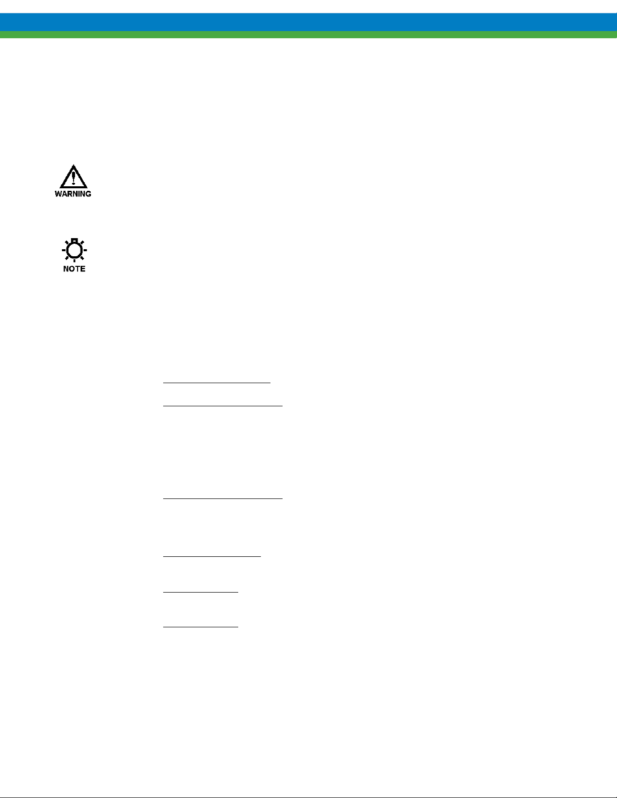
Figure 1
2
Page 9
3. Installation
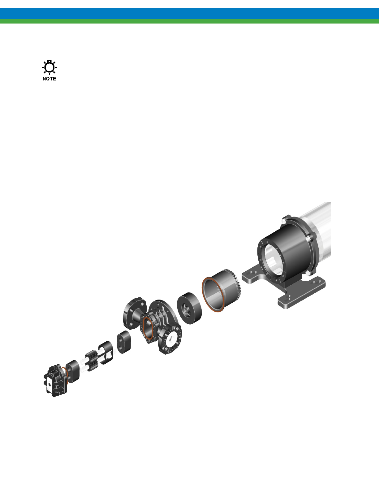
Pump installation site should provide easy access for routine maintenance and protect the pump
from environmental elements and from leaks or drips from nearby process equipment. See
Figure 2 for typical installation diagram.
o Bolt the pump motor down firmly to mounting surface. Provide for air movement and circulation over electric
motor to enhance proper cooling.
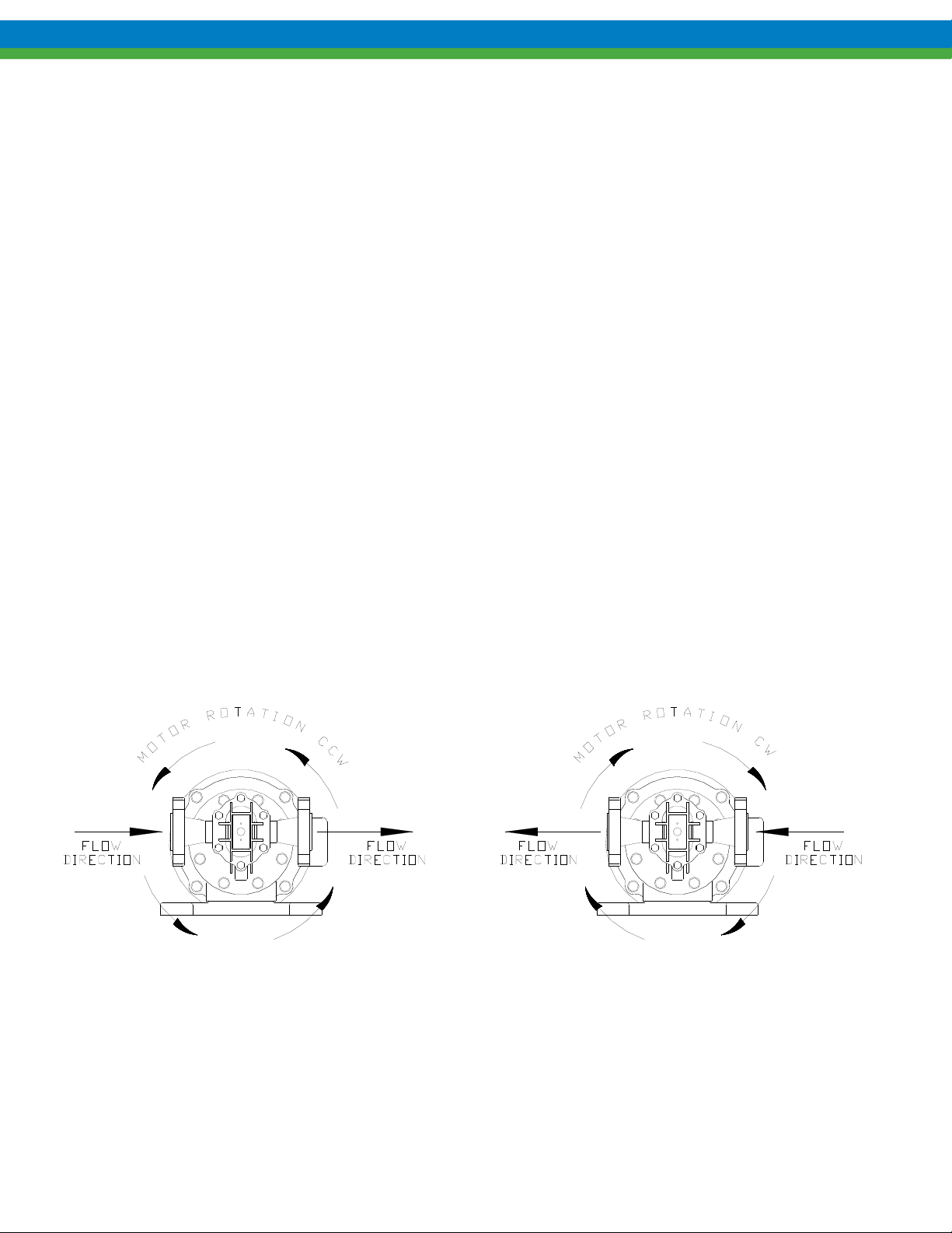
o While looking at the pump from the magnetic drive end, the suction port is to the right when the pump drive
shaft rotates clockwise and is located below the ports. Reversing drive shaft rotation reverses flow and thus
suction and discharge ports. Since the Eclipse Standard/Eclipse Hypo series pumps can be installed both
vertically and horizontally, it is very important to verify proper motor rotation before final piping is
established.
o When installed horizontally, make sure the pump housing drain is on the bottom of the pump. If the pump is
installed with the drain facing upwards, the rotation of the motor will be incorrect and either needs to be
reversed or the pump orientation corrected. Reference the pump drawings in Section 18 of this manual for
drain location.
o Installation of vacuum or pressure gauges in the suction and discharge piping is recommended to properly
monitor system operation.
o Keep suction piping system short and straight to minimize friction loss to the pump. Make sure that the pump
will not run dry. Flooded suction or gravity fed fluid to pump inlet is generally preferred.
o Use only full-bore ball valves or gate valves in the suction piping. If suction strainers are used, size them to
minimize pressure drop and select those of a type that are easily cleaned and maintained.
o Arrange all suction piping and fittings to prevent formation of air pockets. Make sure all joints are airtight.
o Flush and blow out all suction lines prior to mating to pump. Use nipples and unions, for ease of maintenance.
Figure 2a – General Installation
3
Page 10
o Do not force, bend, or spring either suction or discharge piping when mating up to the pump. Use supports or
hangers at intervals as required in an effort to compensate for piping strain due to vector forces and bending
forces. When necessary, install thermal expansion joints or accessories so minimal piping strain is placed
upon the pump.
o Check all bolts and nuts for tightness. Correct any conditions that could cause destructive vibration or
leakage.
o If start-up screens are used, be sure they do not clog and starve suction. Start up screens should be removed
prior to placing system into regular operation.
o If flexible suction lines are used, be sure their selection and installation will prevent wall collapse and thus a
starved suction condition.
o When taking suction from a tank or vessel, avoid entry of sludge or solids into suction line by placing suction
line inlet above maximum expected level of solids.
o Discharge line should be fitted with properly sized pressure relief valve to protect both pump and discharge
system. Pressure relief valve outlet should be piped back to the supply tank.
o When a by-pass system is used to control flow from the pump, the bypassed fluid should be piped back to the
suction vessel to prevent heat build-up due to recirculation cavitation. If it is absolutely necessary to pipe bypass back to the pump suction line, the point of entry should be at least one foot away from the suction inlet.
Provision for cooling should be made in the event of excessive heat buildup through fluid recirculation.
o Where pumped fluids may solidify, cry stallize, or precipitate, provisions should be made to thoroughly flush
pump and piping prior to periods of shutdown. Pay particular attention to proper flushing and draining of the
magnetic coupling area because this area may not completely self drain.
Figure 2b – Flow vs. Motor Rotation
4
Page 11

4. Equipment Setup and Operation
Prior to operation, make sure all suction piping is air tight and clean. Check that electrical service to motor agrees
with nameplate ratings. Jog the motor to check rotation and for signs of binding. To check rotation, observe the
motor fan. Rewire motor if necessary. As noted in Section 3, Installation, Eclipse Standard/Eclipse Hypo Series
pumps are bi-directional, the direction of flow is determined by the direction of motor rotation.
ALTHOUGH THE ECLIPSE STANDARD/ECLIPSE HYPO SERIES PUMPS ARE DESIGNED WITH SOME RUN-
DRY CAPABILITY, IT IS NOT RECOMMENDED THAT ANY MAGNETICALLY DRIVEN PUMP BE RUN DRY. THIS
CONDITION CAN CAUSE SIGNIFICANT TEMPERATURE INCREASES RESULTING IN PREMATURE DAMAGE TO
WEAR SURFACES FROM LACK OF LUBRICATION AND
Pumping fluids containing abrasives should be avoided, as accelerated pump wear will result. Eclipse
Standard/Eclipse Hypo Series gear pumps are designed to handle clear fluids at viscosities up to 10,000 cps.
The pump is designed to self prime if fluid is supplied at the pump inlet. If foot valves are used, the valve should
be of the flapper type and sized to minimize friction loss.
If the pump operates near the boiling point of the pumped fluid, a recirculation loop can be set up between the
discharge and suction connections with provisions for flow control in the recirculation loop.
Power Monitors are strongly recommended for optimum protection of all magnetically driven pumps. Consult
factory for selection and support.
Do not operate the pump against a closed or blocked discharge. Doing so can cause the magnetic drive to
decouple. If decoupling occurs, stop the motor and restart after the obstruction has been cleared.
Operation against closed or blocked discharge can also result in casing pressure that exceeds the pump’s
published safe limits. This can result in damage to the casing parts and/or containment can.
As a safety precaution, a pressure relief valve by-pass system is highly recommended. Ideally, the pressure relief
valve is set for a low pressure at start-up to allow the pump to flood with liquid and evacuate air quickly. It can
then be re-adjusted to a setting appropriate to the application.
Hardware and fasteners can loosen during transportation and installation. All pump hardware should be checked
and verified tight before placing the pump in operation. Consult the table in Section 12 for the recommended
torque values for all pump hardware.
Pump hardware should be checked on a regular basis, especially if the pump is subject to temperature variations
or cycling that might cause it to loosen during operation.
Start pump with discharge and suction valves open and check for proper operation. Excessive noise or vibration
is an indication of harmful cavitation, which may be due to insufficient NPSH (Net Positive Suction Head).
/OR VAPORIZATION OF LIQUID IN THE PUMP.
5
Page 12
5. Maintenance Overview
The timing for maintenance of the pump is established primarily on past performance. Each installation is
different. Therefore, regular inspections, and detailed maintenance records of past performance can be invaluable
for determining future preventative maintenance intervals. For motor maintenance instructions consult the motor
manufacturer.
BEFORE PERFORMING ANY MAINTENANCE REQUIRING PUMP DISASSEMBLY, BE SURE TO FLUSH AND
DRAIN PUMP THOROUGHLY WITH A NEUTRALIZING FLUID
EQUIPMENT WITH PROPER CARE
When changing a pump from one service to another, be sure to check that all wetted parts of the pump are
compatible with the fluid to be handled and that the motor is sufficiently sized for the application. If in doubt
contact your Pulsafeeder representative for assistance.
All magnetic drive couplings have a specific maximum torque limit. If this torque is exceeded
the drive will decouple. Operation in the decoupled mode should be avoided as high
temperatures could be generated.
.
. WEAR PROTECTIVE CLOTHING AND HANDLE
Whenever gear pumps exhibit reduced flow rates, inability to maintain pressures, noisy or otherwise abnormal
operation, first refer to the troubleshooting section at the end of this manual. If the problem cannot be resolved the
pump must be inspected for wear or damage. Eclipse Standard/Eclipse Hypo Series gear pumps can be easily
opened for cleaning and inspection without disturbing piping connections by removing the pump front housing
cover.
Where inspection shows wear, rebuilding the pump using a KOPKit is strongly recommended. Quite often,
original hydraulic performance can be restored by simply changing the KOPKit alone.
Magnets (both drive and driven) can attract small particles of debris during handling. Always visually
inspect the magnetic parts of the pump for cleanliness during re-assembly. Wipe carefully to remove
debris, particles, or other small parts without damaging the surface of the magnets.
6
Page 13

5.1 Recommended Spares
KOPKits – The basic Eclipse Standard/Eclipse Hypo Series KOPKit consists of the following parts, which are
recommended as typical spare parts. The KOPKit provides an easy means to keep the right parts for your Eclipse
Standard/Eclipse Hypo Series pump close at hand.
Drive Gear and Shaft Assembly 1 each
Idler Gear and Shaft Assembly 1 each
Housing Liner 1 each
Bearings 2 each
O-Rings 3 or 4 each
The model number stamped on the pump nameplate identifies the pump type and other details. Refer to the model
number chart if you are unsure of exactly what type of pump you have, or when ordering parts or KOPKits.
Always refer to the full model and serial number in
Drawings and consolidated bill of materials for each size pump are included in this manual. Recommended spare
parts are identified on the consolidated bill of materials.
any correspondence with your Pulsafeeder representative.
5.2 Maintenance precautions for magnet-driven equipment:
Non-magnetic tools and non-magnetic work surfaces are recommended to perform any disassembly or
maintenance of the pump.
Do not wear a wristwatch in the vicinity of the drive or driven magnets, wristwatches may be damaged
by the transmission of magnetic flux.
The strong magnetic field will damage credit cards, security badges, or other magnetic data strips.
Keep them a safe distance from the magnets.
Take precautions in handling pump magnets if you have prosthetic devices, metal or medical inserts
installed in your body. Consult your physician for guidance in handling magnets.
Completely flush and drain pump prior to pump disassembly.
The exposed magnets on the drive magnet assembly are very fragile and will chip easily. Use extreme
care in handling them.
Take care to avoid magnetic particles or objects from attaching themselves to the drive magnets. It is
difficult to remove small particles, and larger objects could be attracted with enough force to break the
magnets.
BE CAREFUL DURING DISASSEMBLY AND REASSEMBLY OF THE DRIVE AND DRIVEN MAGNET
ASSEMBLIES
CLOSE TOGETHER THERE IS A STRONG TENDENCY TO SNAP TOGETHER SUDDENLY
CAUSING INJURY TO FINGERS OR FLESH
. THE MAGNETIC ATTRACTION FORCES ARE HIGH, AND WHEN THE MAGNETS COME
D
O NOT MACHINE THE MAGNETS OR MAGNET CARRIERS IN THE DRIVE OR DRIVEN MAGNET
ASSEMBLIES
. THE MAGNETIC DUST THAT WOULD BE PRODUCED IS HIGHLY FLAMMABLE.
, POTENTIALLY
.
7
Page 14
5.3 KOPKit Maintenance, All Models
All Eclipse Standard/Eclipse Hypo gear pumps are designed for easy access to the regularly serviced internal
components. These components are part of the KOPKit described in Section 5.1.
The KOPKit for an Eclipse Standard/Eclipse Hypo pump can be installed without removing the pump from
service. The pump can be disassembled in the horizontal position while still connected to the process lines.
Special precautions must be taken to ensure the pump is safe to work on.
BEFORE PERFORMING ANY MAINTENANCE REQUIRING PUMP DISASSEMBLY, BE SURE TO RELIEVE
PRESSURE FROM THE PIPING SYSTEM
SHUTOFF
RENDER THE PUMP SAFE TO PERSONNEL AND THE ENVIRONMENT BY CLEANING AND CHEMICALLY
NEUTRALIZING AS APPROPRIATE
The following sections of the IOM review disassembly and assembly of the Eclipse Standard/Eclipse Hypo pump
on the service bench. If you are working on your Eclipse Standard/Eclipse Hypo pump in the field, the same
procedures are used except that your pump will be horizontally mounted, whereas the illustrations in the IOM
sections show the pumps in a vertical position.
/BLOCKING DEVICES, AND, WHERE HAZARDOUS PROCESS MATERIALS ARE INVOLVED,
, ISOLATE THE PUMP FULLY USING THE APPROPRIATE
. WEAR PROTECTIVE CLOTHING AND EQUIPMENT AS REQUIRED.
Figure 3
8
Page 15
6. Disassembly/Assembly, Eclipse Standard/Eclipse Hypo 02
BEFORE PERFORMING ANY MAINTENANCE REQUIRING PUMP DISASSEMBLY, BE SURE TO RELIEVE
PRESSURE FROM THE PIPING SYSTEM AND
RENDER THE PUMP SAFE TO PERSONNEL AND THE ENVIRONMENT BY CLEANING AND CHEMICALLY
NEUTRALIZING AS APPROPRIATE
. WEAR PROTECTIVE CLOTHING AND EQUIPMENT AS APPROPRIATE.
, WHERE HAZARDOUS PROCESS MATERIALS ARE INVOLVED,
6.1 Disassembly
Close all suction and discharge valves.
Disconnect power source to motor.
Flush and drain pump
Remove piping (optional for KOPKit).
NOTE: The can area will not fully drain and will contain some process fluid.
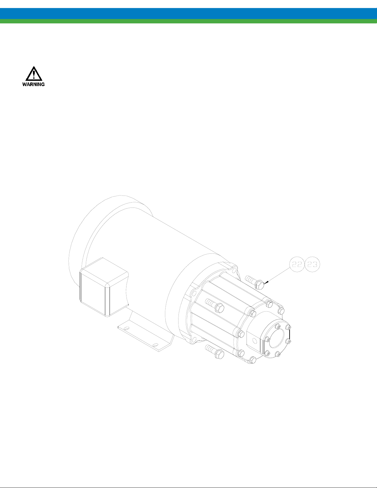
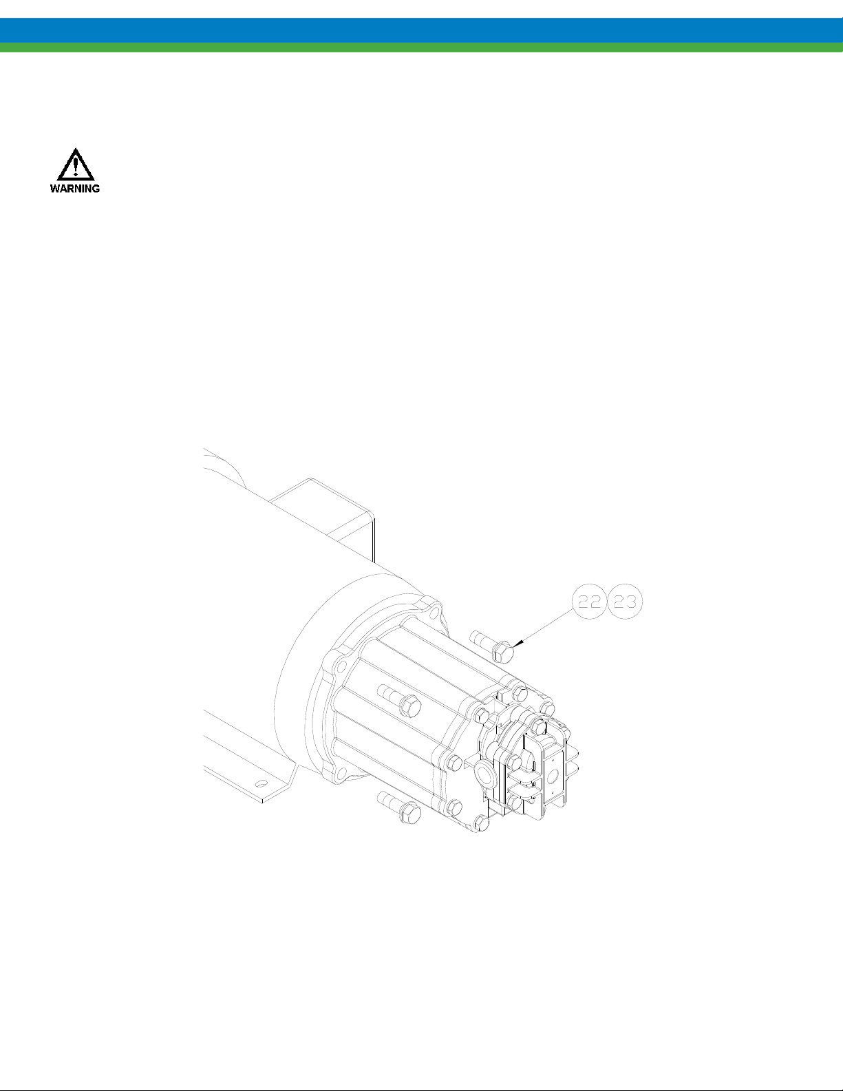
1. Remove the four motor bolts and washers (items 22, 23) and slide the entire pump straight off the motor.
Figure 4
2. Place pump assembly (motor spool down) on the work surface.
9
Page 16
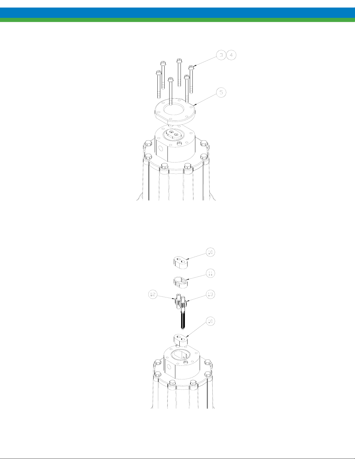
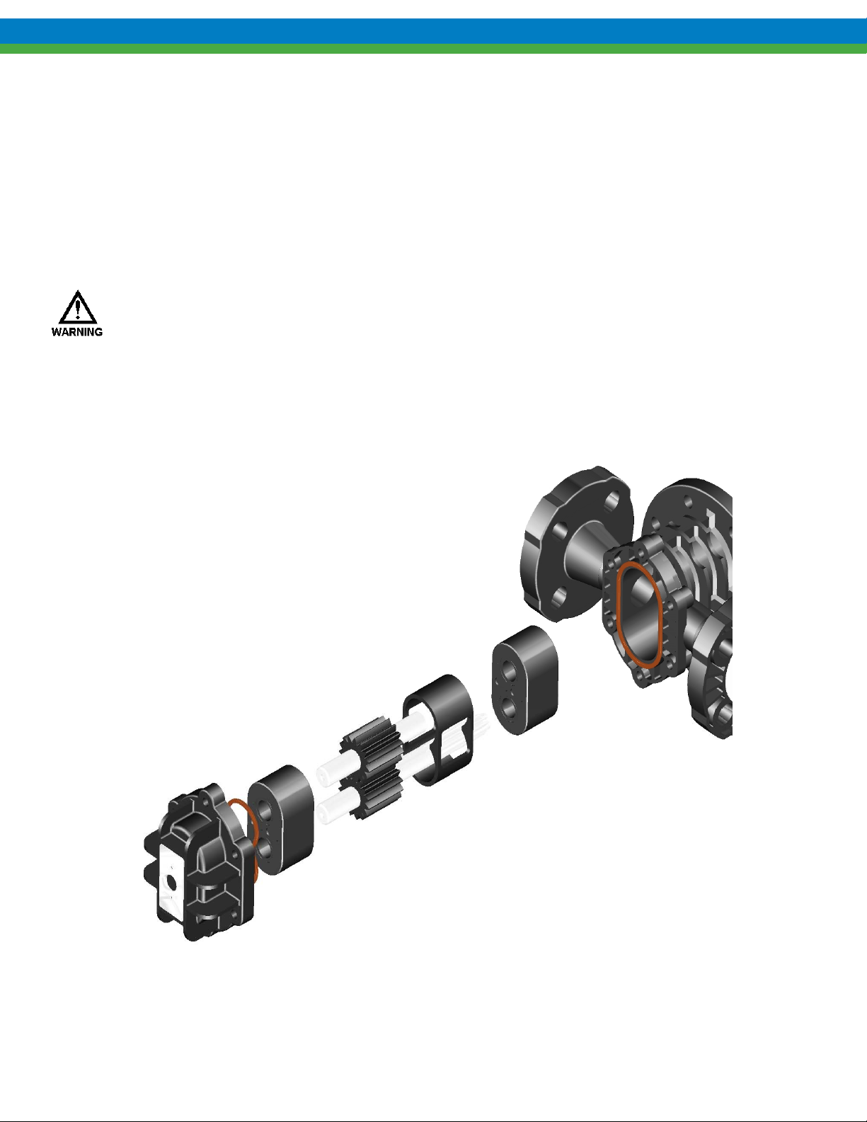
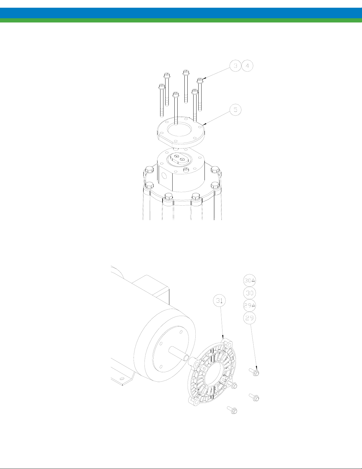
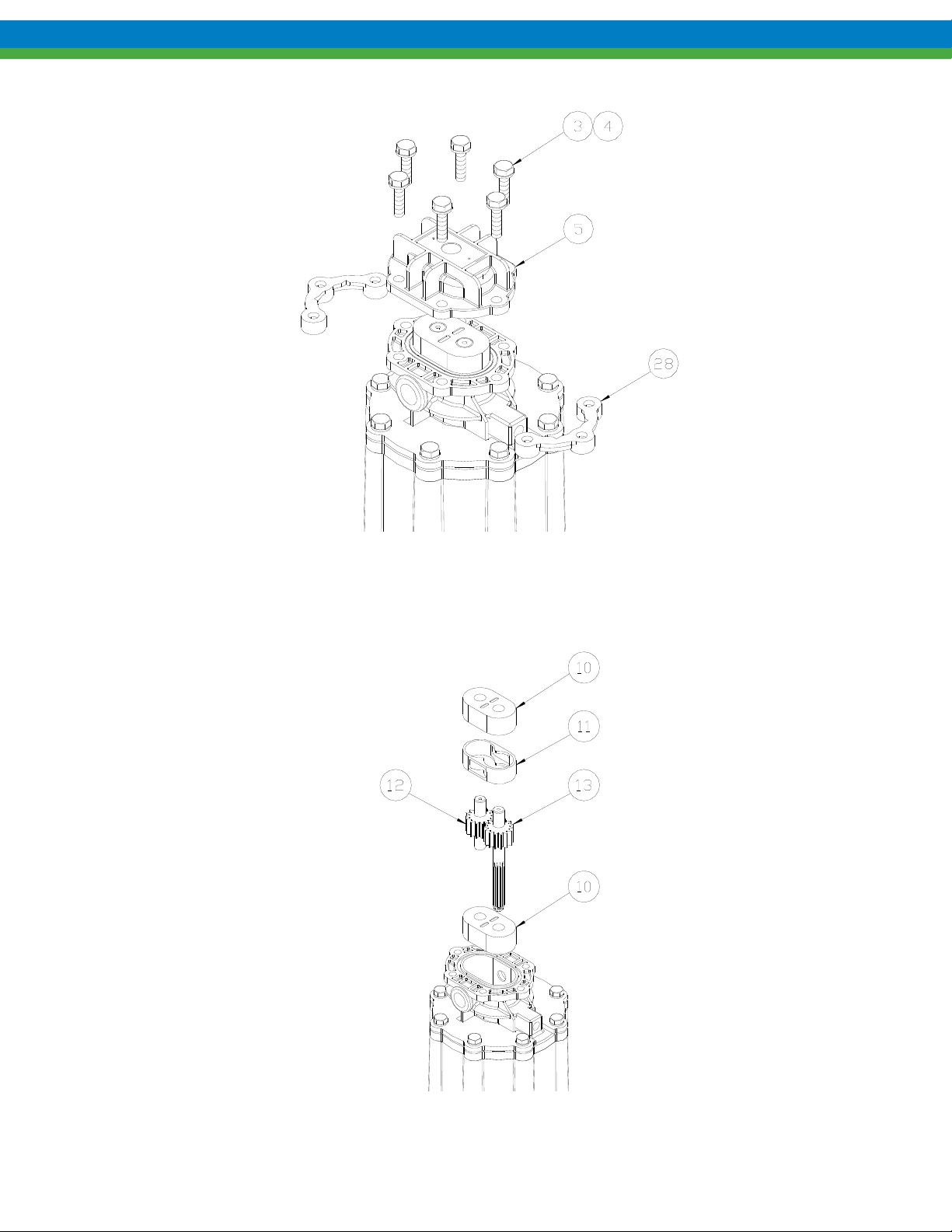
3. Remove the six bolts and flat washers (items 3, 4) and remove front cover (item 5) as shown.
Figure 5
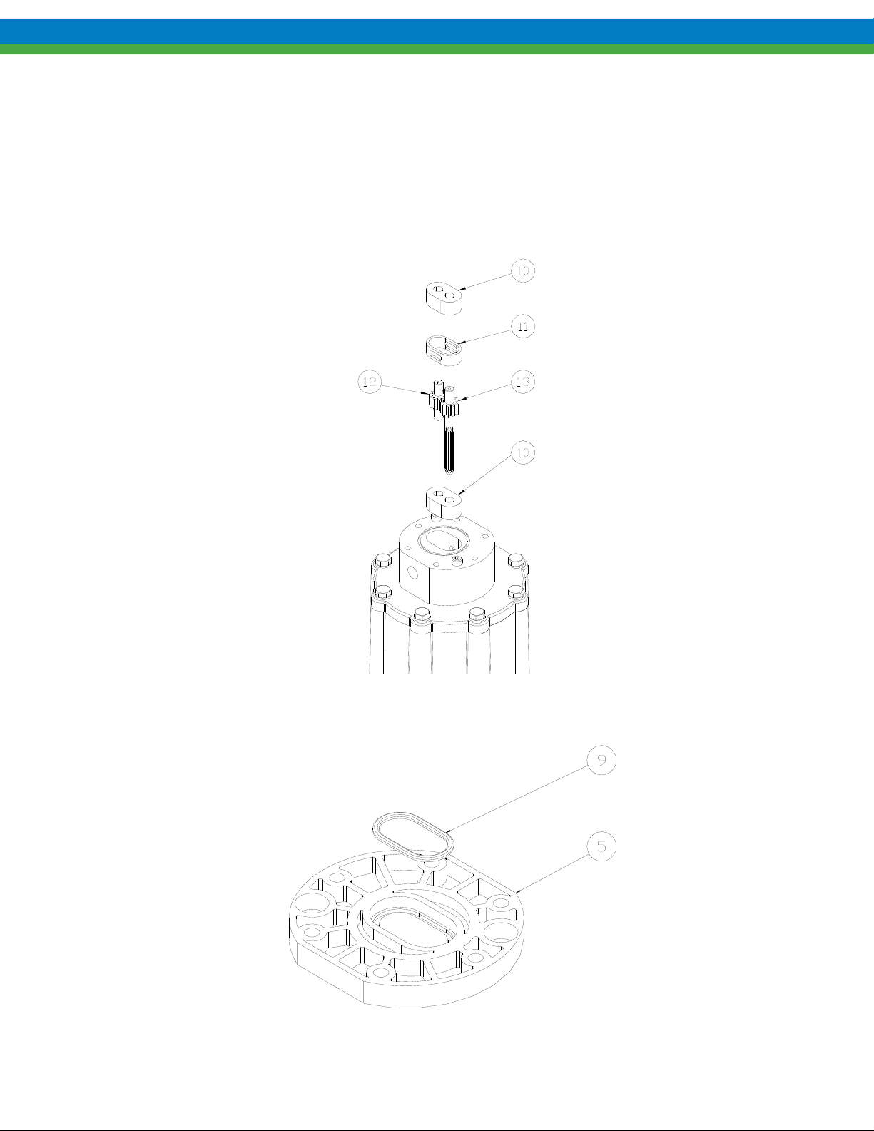
4. Remove bearings (item 10), gear/shaft assemblies (items 12, 13) and housing liner (item11) as shown. These
parts, along with the three o-rings make up a standard Eclipse Standard/Eclipse Hypo Series KOPKit. Check
parts for wear and replace with a KOPKit as required.
Figure 6
10
Page 17
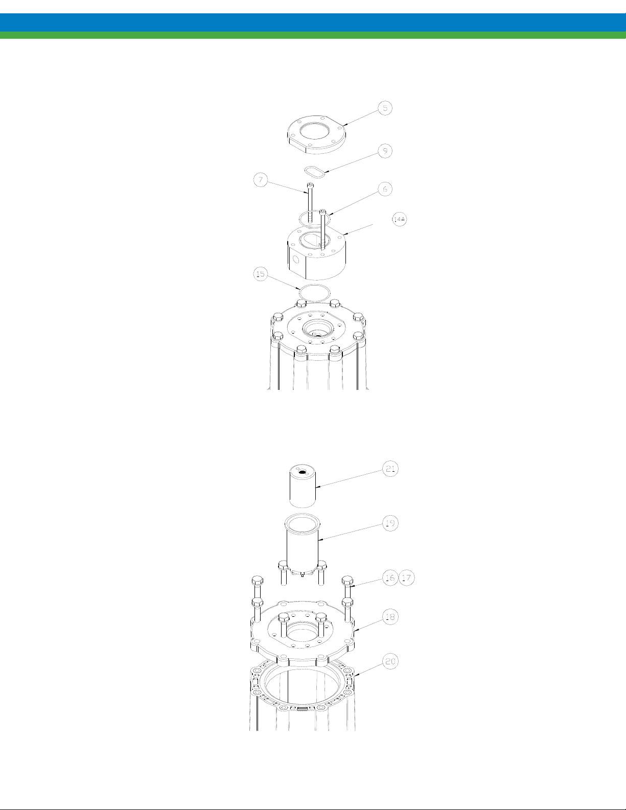
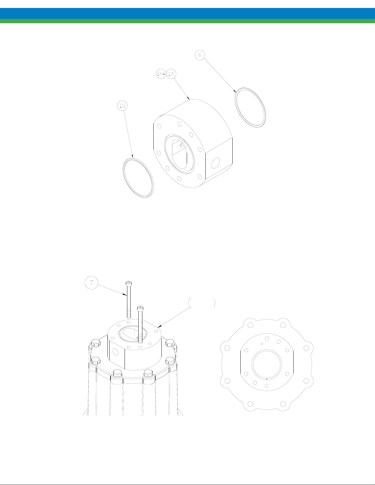
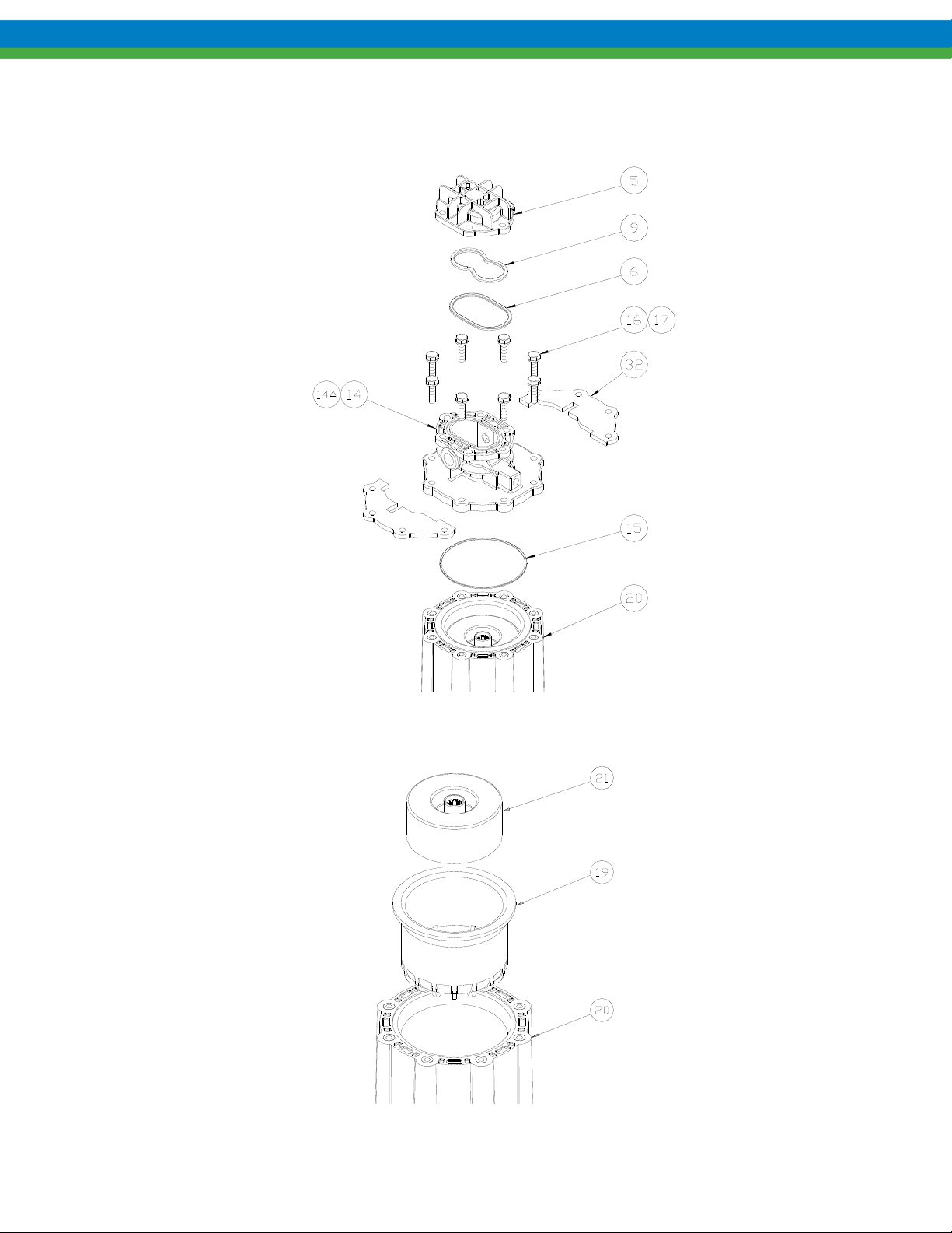
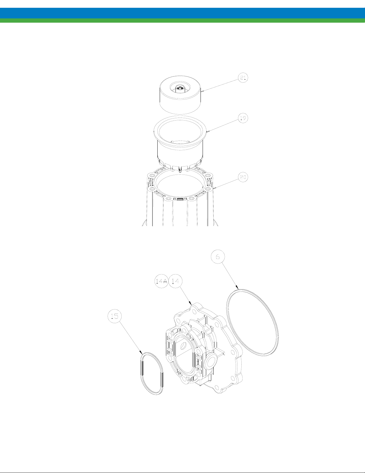
5. Remove the two remaining bolts (item 7) to detach the center housing (item 14).
6. Remove all o-rings from the center housing and front cover. There are two in the center housing (items 6 and 15)
and one in the front cover (item 9) as shown.
Figure 7
7. Remove the eight mounting bolts and washers (items 16, 17) holding the adapter plate (item 18) to the motor
spool (item 20) and detach the adapter plate.
8. Remove driven magnet assembly (item 21) and containment can (item 19) from adapter plate as shown.
Figure 8
11
Page 18
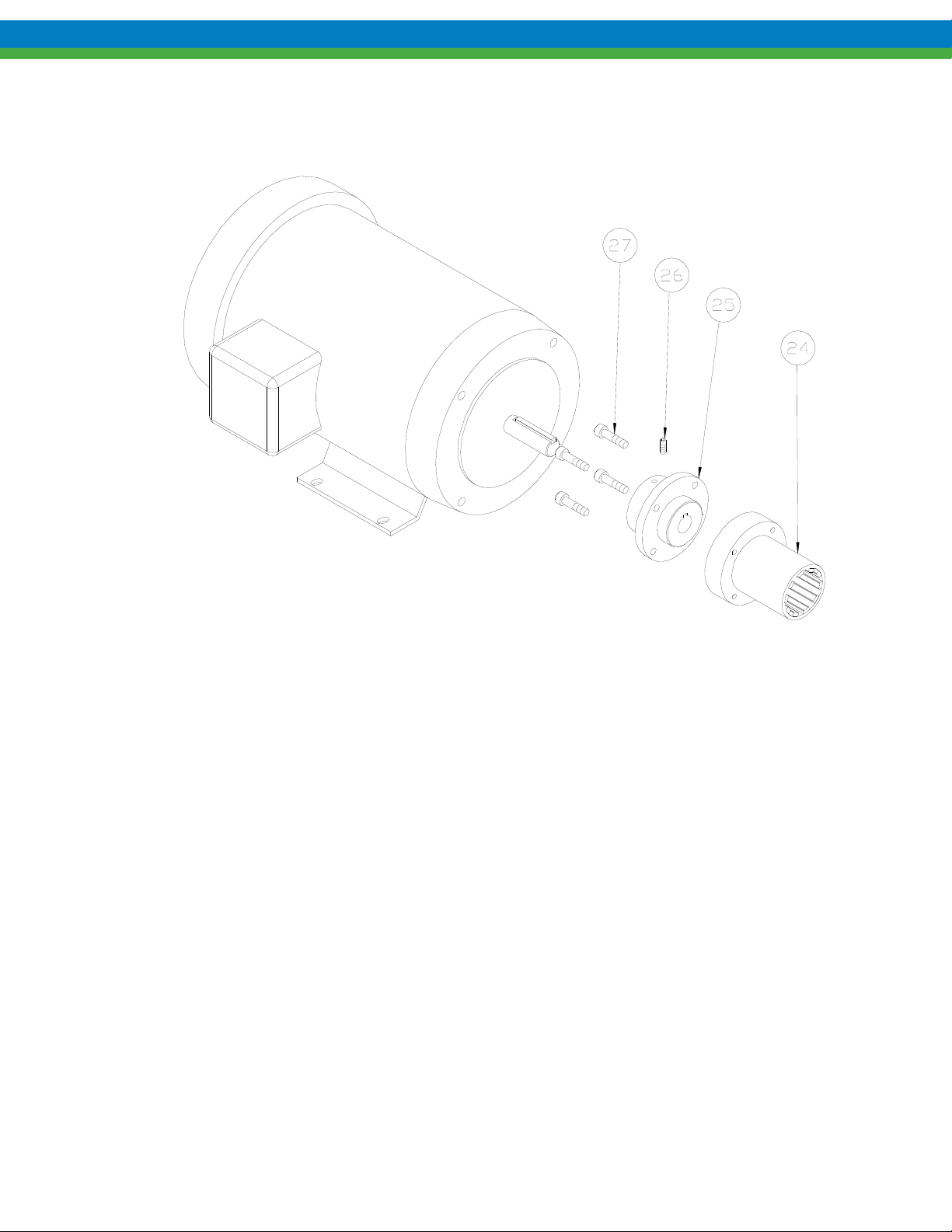
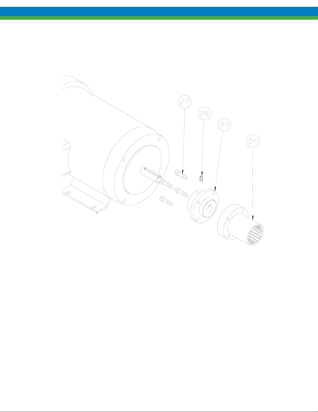
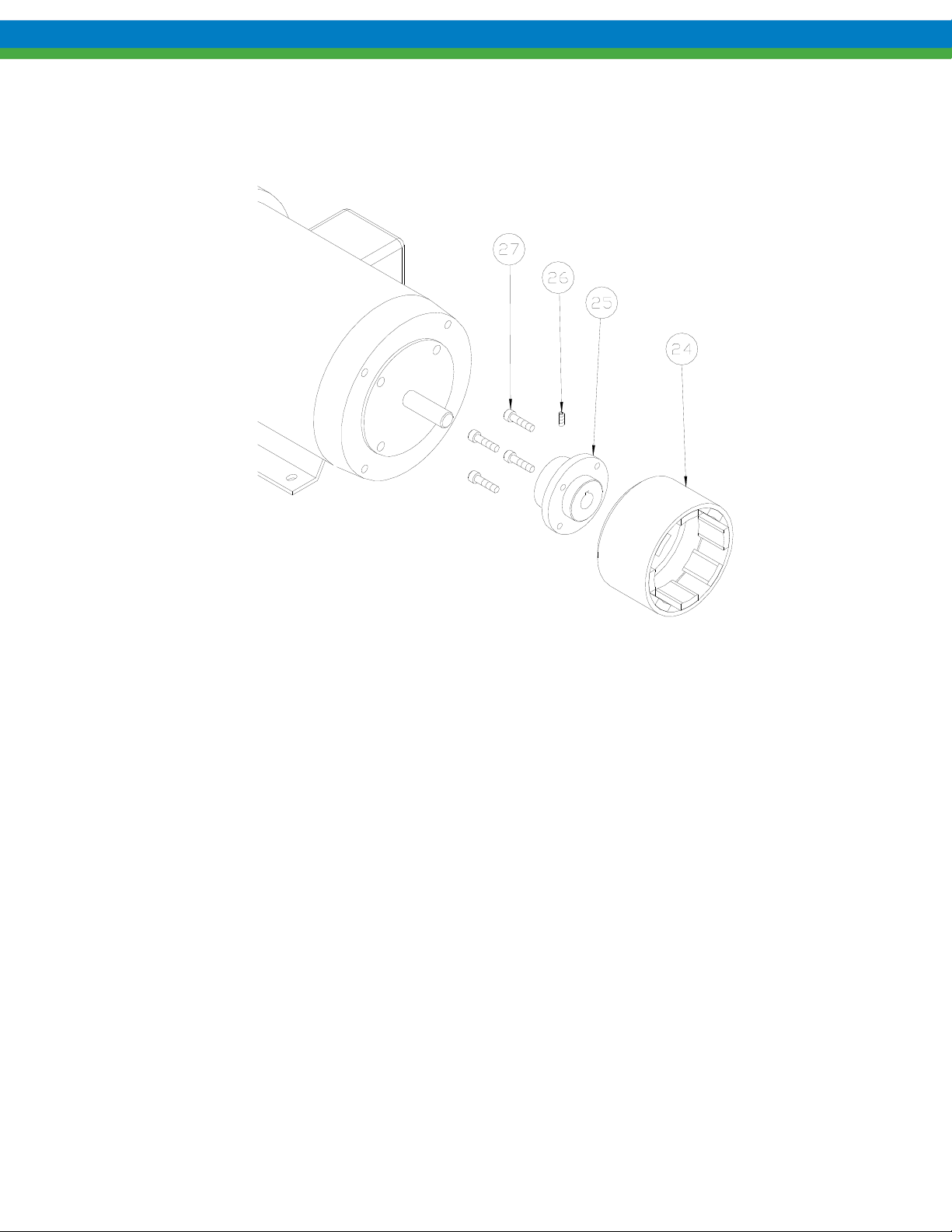
9. Remove drive magnet assembly (item 24) from the motor by loosening the setscrew (item 26) in the magnet hub
and slide off the motor shaft. Retain the key from the motor shaft.
10. If required, the magnet hub (item 25) can be separated from the drive magnet (item 24) by removing the four
screws (item 27) and detaching.
6.2 Inspection
Refer to Section 9, Inspection and Wear Limits, for details.
Figure 9
12
Page 19
6.3 Assembly
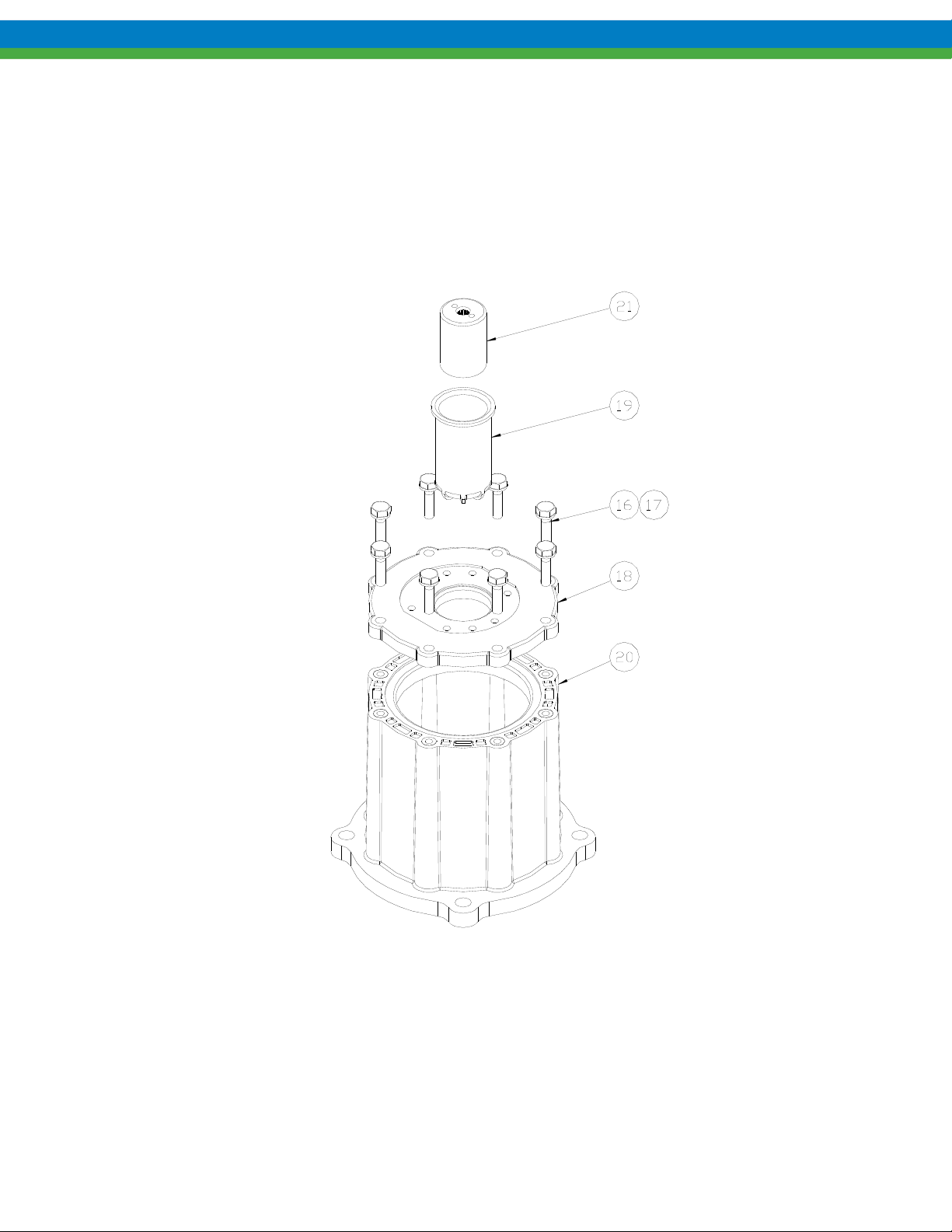
1. Place motor spool (item 20) flat on work surface. Align “molded-in” flats on the spool adapter plate (item 18)
with any two of the motor mounting bolt holes on the motor spool as shown.
2. Set in place and install eight mounting bolts and washers (items 16, 17). Tighten these bolts to the torque
specified in Section 12. Always tighten fasteners in a progressive “crisscross” pattern.
3. Install the containment can (item 19) into the spool adapter plate until it is properly seated into the assembly.
4. Install the driven magnet assembly (item 21) into the containment can. The driven magnet is symmetrical and can
be inserted with either end facing out (orientation does not matter).
Figure 10
5. Inspect all o-rings to be sure there is no damage such as pinching prior to assembly.
13
Page 20
6. Install o-rings (items 6, 15) into grooves on both sides of the center housing. Some o-ring lubricant may help
keep the o-rings in place during assembly. Be sure both o-rings are fully seated into housing grooves.
Figure 11
7. Place the center housing (item 14) with o-rings installed onto the spool adapter plate (open bore facing out),
aligning the flat sides on the center housing to the flat sides on the spool adapter plate as shown. If the center
housing does not sit flat, rotate 180º until it seats into place.
8. Secure the center housing using 2 bolts (item 7) in holes as shown. Tighten these bolts to the torque specified in
Section 12. Always tighten fasteners in a progressive “crisscross” pattern.
Figure 12
14
Page 21
9. Insert a bearing (item 10) into the center housing (item 14) and slide to the bottom of the housing. Bearings are
symmetrical and orientation does not matter.
10. Install the housing liner (item 11) and slide until it seats against the first bearing. Install the idler gear (item 12)
into the top hole in bearing until the gear seats against the first bearing.
11. Install the drive gear (item 13), splined-end first, into the assembly until it bottoms out against the bearing. The
shaft may have to be rotated slightly to properly fit the splined-end into the drive magnet and gear to the idler gear
assembly.
12. Insert the second bearing (item 10) into the housing bore until it rests against the housing liner. Bearings are
symmetrical and orientation does not matter.
Figure 13
13. Install the spacer o-ring (item 9) into front cover as shown. Some o-ring lubricant may help keep the o-rings in
place during assembly.
Figure 14
15
Page 22
14. Install front cover with spacer o-ring using the six bolts and washers. Tighten these bolts to the torque specified
in Section 12. Always tighten fasteners in a progressive “crisscross” pattern.
Figure 15
15. For IEC frame motors only, if it was removed, install the motor adaptor plate (item 31) onto the motor face using
the four bolts and washers (items 29 and 30). Always tighten fasteners in a progressive “crisscross” pattern.
Figure 16
16
Page 23
16. Secure the magnet hub (item 25) to the drive magnet (item 24) using the four screws (item 27). Always tighten
fasteners in a progressive “crisscross” pattern.
Figure 17
17
Page 24
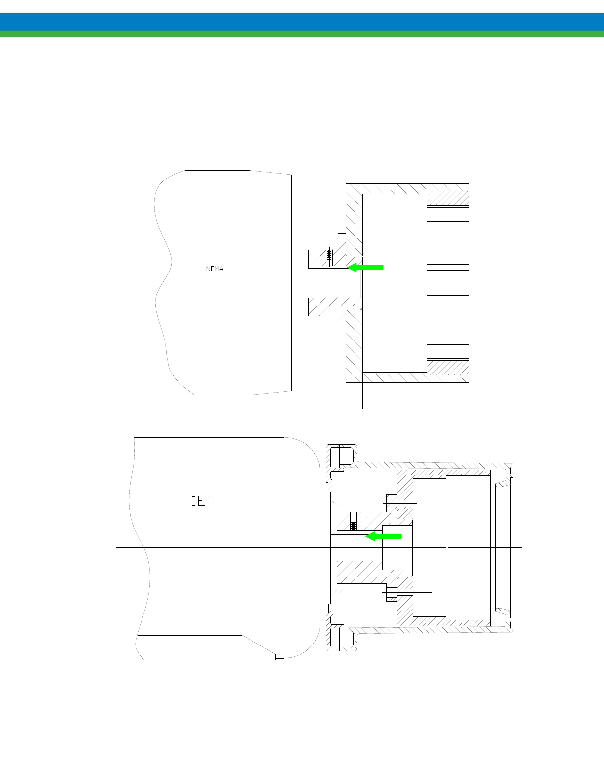
17. Align the keyway, and slide the drive magnet onto the motor shaft until the end of the motor shaft aligns with
faces of the drive magnet motor hub as shown below. Secure with the setscrew (item 26). Application of a noseize compound on the shaft and key will make future maintenance easier.
18. Complete assembly by replacing the assembled pump onto the motor, using care not to allow fingers to get
pinched when the magnets attract. Secure the pump to the motor with the four bolts and washers (items22, 23).
Always tighten fasteners in a progressive “crisscross” pattern.
Figure 18
18
Page 25
7. Disassembly/Assembly, Eclipse Standard/Eclipse Hypo 05/12
BEFORE PERFORMING ANY MAINTENANCE REQUIRING PUMP DISASSEMBLY, BE SURE TO RELIEVE
PRESSURE FROM THE PIPING SYSTEM AND
RENDER THE PUMP SAFE TO PERSONNEL AND THE ENVIRONMENT BY CLEANING AND CHEMICALLY
NEUTRALIZING AS APPROPRIATE
. WEAR PROTECTIVE CLOTHING AND EQUIPMENT AS APPROPRIATE.
, WHERE HAZARDOUS PROCESS MATERIALS ARE INVOLVED,
7.1 Disassembly
Close all suction and discharge valves.
Disconnect power source to motor.
Flush and drain pump
Remove piping (optional for KOPKit).
NOTE: The can area will not fully drain and will contain some process fluid.
1. Remove the four motor bolts and washers (items 22, 23) and slide the entire pump straight off the motor.
Figure 19
2. Place pump assembly (motor spool down) on the work surface.
19
Page 26
3. Remove the six bolts and washers (items 3, 4), remove front cover (item 5) and nut plates (item 28) as shown.
Figure 20
4. Remove bearings (item 10), gear/shaft assemblies (items 12, 13) and housing liner (item 11) as shown. These
parts, along with the four o-rings make up a standard Eclipse Standard/Eclipse Hypo Series KOPKit. Check parts
for wear and replace with a KOPKit as required.
Figure 21
20
Page 27
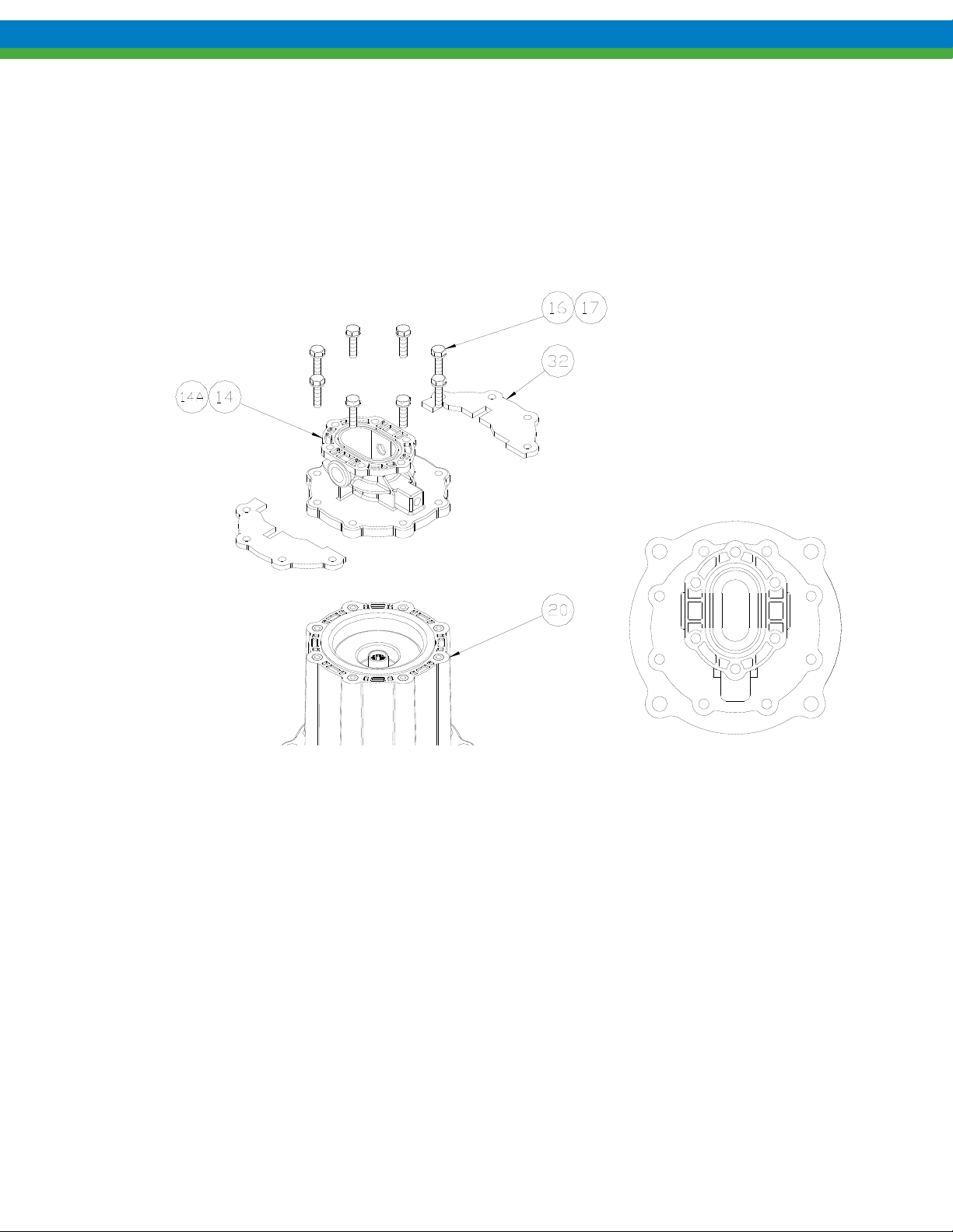
5. Remove the eight mounting bolts and washers (items 16, 17) holding the center housing (item 14) to the motor
spool (item 20). Remove the center housing and retaining plates (item 32).
6. Remove all o-rings from the center housing and front cover. There are two o-rings in the center housing (items 6,
15) and one in the front cover (item 9) as shown.
Figure 22
7. Remove driven magnet assembly (item 21) and containment can (item 19) from the motor spool (item 20) as
shown.
Figure 23
21
Page 28
8. Remove drive magnet assembly from the motor by loosening the setscrew (item 26) in the magnet hub (item 25)
and slide off the motor shaft. Retain the key from the motor shaft.
9. If required, the magnet hub (item 25) can be separated from the drive magnet (item 24) by removing the four
screws (item 27) and detaching.
7.2 Inspection
Refer to Section 9, Inspection and Wear Limits, for details.
Figure 24
22
Page 29
7.3 Assembly
1. Place motor spool (item 20) flat on work surface.
2. Insert the containment can (item 19) and driven magnet (item 21) into the motor spool as shown. The driven
magnet is symmetrical and orientation does not matter.
Figure 25
3. Inspect all o-rings to be sure there is no damage such as pinching prior to assembly.
Figure 26
23
Page 30
4. Install o-rings (items 6, 15) into each side of the center housing (item 14) as shown. Some o-ring lubricant
may help keep the o-rings in place during assembly. Be sure both o-rings are fully seated into housing
grooves.
5. Place the center housing, with o-rings, onto the motor spool, aligning the port connections between any set of
motor spool bolt holes as shown. Add the retaining plates (item 32). Secure with eight bolts and washers
(items 16, 17). Tighten these bolts to the torque specified in Section 12. Always tighten fasteners in a
progressive “crisscross” pattern.
Figure 27
6. Insert a bearing (item 10) into center housing and slide to bottom of bore. Bearings are symmetrical and
orientation does not matter. Install the housing liner (item 11) and slide until it seats against the first bearing.
Install idler gear (item 12) into the top hole in bearing until the gear seats against the first bearing.
7. Install the drive gear (item 13), splined-end first, into the assembly until it bottoms out against the bearing.
The shaft may have to be rotated slightly to properly fit the splined-end into the drive magnet and mesh gear
teeth with the idler gear.
24
Page 31

8. Insert the second bearing (item 10) into the housing bore until it rests against the housing liner. Bearings are
symmetrical and orientation does not matter.
Figure 28
9. Install the spacer o-ring (item 9) into the front cover (item 5) as shown. Some o-ring lubricant may help keep
the o-rings in place during assembly.
Figure 29
25
Page 32

10. Place the front cover (item 5) with o-ring onto the assembled pump. Secure the front cover using the six bolts
and washers (items 3, 4) and two nut plates (item 28) as shown. The flat side of the nut plates mate against
the back of the center housing flange. Tighten these bolts to the torque specified in Section 12. Always
tighten fasteners in a progressive “crisscross” pattern.
Figure 30
11. For IEC frame motors only, if it was removed, install the motor adaptor plate (item 31) onto the motor face
using the four bolts and washers (items 29 and 30). Always tighten fasteners in a progressive “crisscross”
pattern.
Figure 31
26
Page 33

12. Secure the magnet hub (item 25) to the drive magnet (item 24) using the four screws (item 27). Always
tighten fasteners in a progressive “crisscross” pattern.
Figure 32
27
Page 34

13. Align the keyway, and slide the drive magnet onto the motor shaft until the end of the motor shaft aligns with
faces of the drive magnet motor hub as shown below. Secure with the setscrew (item 26). Application of a noseize compound on the shaft and key will make future maintenance easier.
14. Complete assembly by replacing the assembled pump onto the motor, using care not to allow fingers to get
pinched when the magnets attract. Secure the pump to the motor with the four bolts and washers (items
22,23). Always tighten fasteners in a progressive “crisscross” pattern.
Figure 33
28
Page 35

8. Disassembly/Assembly, Eclipse Standard/Eclipse Hypo 25/75/125
BEFORE PERFORMING ANY MAINTENANCE REQUIRING PUMP DISASSEMBLY, BE SURE TO RELIEVE
PRESSURE FROM THE PIPING SYSTEM AND
RENDER THE PUMP SAFE TO PERSONNEL AND THE ENVIRONMENT BY CLEANING AND CHEMICALLY
NEUTRALIZING AS APPROPRIATE
. WEAR PROTECTIVE CLOTHING AND EQUIPMENT AS APPROPRIATE.
, WHERE HAZARDOUS PROCESS MATERIALS ARE INVOLVED,
8.1 Disassembly
Close all suction and discharge valves.
Disconnect power source to motor.
Flush and drain pump
Remove piping (optional for KOPKit).
NOTE: The can area will not fully drain and will contain some process fluid
1. Remove the four motor bolts and washers (items 22, 23) and slide the entire pump straight off the motor.
Figure 34
2. Place pump assembly (motor spool down) on the work surface.
3. Remove the six bolts and washers (items 3, 4), remove front cover (item 5) and nut plates (item 28) as shown.
4. If required, the mounting base (item 32) can be detached by removing the four bolts and washers (items 33,
34) as shown.
29
Page 36

Figure 35
5. Remove bearings (item 10), gear/shaft assemblies (items 12, 13) and housing liner (item 11) as shown. These
parts, along with the four o-rings make up a standard Eclipse Standard/Eclipse Hypo Series KOPKit. Check
parts for wear and replace with a KOPKit as required.
Figure 36
6. Remove the eight mounting bolts and washers (items 16, 17) holding the center housing (item 14) to the
motor spool (item 20). Detach the center housing and retaining plates (item 35).
7. Remove all o-rings from the center housing and front cover. There is one o-ring in the center housing (item
15) and two in the front cover (items 6, 9) as shown.
30
Page 37

Figure 37
8. Remove driven magnet assembly (item 21) and containment can (item 19) from the motor spool (item 20) as
shown.
Figure 38
9. Remove drive magnet assembly from the motor by loosening the setscrew (item 26) in the magnet hub (item
25) and slide off the motor shaft. Retain the key from the motor shaft.
10. If required, the magnet hub (item 25) can be separated from the drive magnet (item 24) by removing the four
screws (item 27) and detaching.
31
Page 38

8.2 Inspection
Refer to Section 9, Inspection and Wear Limits, for details.
Figure 39
32
Page 39

8.3 Assembly
1. Place motor spool flat on work surface.
2. Insert containment can (item 19) and driven magnet (item 21) into motor spool (item 20) as shown. The
driven magnet is symmetrical and orientation does not matter.
Figure 40
3. Inspect all o-rings to be sure there is no damage such as pinching prior to assembly.
Figure 41
33
Page 40

4. Install o-ring (item 15) into the back side of the center housing (item 14) as shown. Some o-ring lubricant
may help keep the o-rings in place during assembly. Be sure the o-ring is fully seated into housing groove.
Figure 42
5. Place the center housing (item 14) onto the motor spool, aligning the port connections with the pump
baseplate as shown. Place the two retaining plates (item 35) onto the center housing and secure with eight
bolts and washers (items 16, 17). Tighten bolts to the torque specified in Section 12. Always tighten fasteners
in a progressive “crisscross” pattern.
6. Insert a bearing (item 10) into center housing (item 14) and slide to bottom of bore. Bearings are symmetrical
and orientation does not matter. Install the housing liner (item 11) and slide until it seats against the first
bearing. Install idler gear (item 12) into the top hole in the bearing until the gear seats against the first
bearing.
7. Install the drive gear (item 13), splined-end first, into the assembly until it bottoms out against the bearing.
The shaft may have to be rotated slightly to properly fit the splined-end into the drive magnet and mesh gear
teeth with the idler gear.
34
Page 41

8. Insert the second bearing into the housing bore until it rests against the housing liner. Bearings are
symmetrical and orientation does not matter.
Figure 43
9. Install the two o-rings (items 6, 9) into the front cover (item 5) as shown. Some o-ring lubricant may help
keep the o-rings in place during assembly.
Figure 44
35
Page 42

10. Place the front cover (item 5) with o-ring onto the assembled pump. Secure the front cover using the six bolts
and washers (items 3, 4) and two nut plates (item 28) as shown. The flat side of the nut plates mates against
the back of the center housing flange. Tighten bolts to the torque specified in Section 12. Always tighten
fasteners in a progressive “crisscross” pattern.
Figure 44
11. Secure the mounting base (item 32) to the motor spool (item 20) using the four bolts and washers (items 33,
34) as shown. Always tighten fasteners in a progressive “crisscross” pattern.
36
Page 43

12. If it was removed, install the motor adaptor plate (item 18) onto the motor face using the four bolts and
washers (items 29 and 30). Always tighten fasteners in a progressive “crisscross” pattern.
NOTE: E125 May use (2) Adaptor Plates, ref #18.
Figure 45
13. Secure the magnet hub (item 25) to the drive magnet (item 24) using the four screws (item 27). Always
tighten fasteners in a progressive “crisscross” pattern.
Figure 46
37
Page 44

14. Align the keyway, and slide the drive magnet onto the motor shaft until the end of the motor shaft aligns with
faces of the drive magnet motor hub as shown below. Secure with the setscrew (item 26). Application of a noseize compound on the shaft and key will make future maintenance easier.
15. Complete assembly by replacing the assembled pump onto the motor, using care not to allow fingers to get
pinched when the magnets attract. Secure the pump to the motor with the four bolts and washers (items 22,
23). Always tighten fasteners in a progressive “crisscross” pattern.
Figure 47
38
Page 45

9. Inspection and Wear Limits
Inspect internal pump components as follows:
9.1.1 Bearings
Inspect bearing bores (2) and end surfaces for wear and scoring. If wear or scoring is present on the end surface
of the bearing, the bearing can be flipped to expose the undamaged face to the gear side. Bearing should be
replaced when both ends show wear and/or scoring, or when the bores have reached the replacement limit (see
chart).
9.1.2 Shafts
Both the idler and the drive shaft should be inspected carefully for scoring, wear, and any signs of cracking or
chips in the surface of the ceramic material. No cracks or chips are allowed. Shafts should be replaced if they
show signs of cracks or chips anywhere on the surface, if they are deeply scored, or if they have reached their
replacement limit (see chart).
9.1.3 Gears
Gears can be measured for dimensional change to their length and outside diameter. Gear teeth should also be
visually inspected for wear and damage. Gear teeth can be damaged due to solids moving through the pump,
which will affect only some teeth, or excessive pressure, which will distort the outside tips of all teeth. Gears that
have reached their replacement limits (see chart) or show signs of physical damage or distortion should be
replaced. Backlash can be checked by temporarily inserting the two gear/shaft assemblies into known good
bearings and observing gear tooth mesh and backlash.
9.1.4 Housing Liner
The housing liner should be visually inspected for scoring, wear, and steps on the ID of the two gear bores. See
chart for specific limits.
9.1.5 Special Note, Viscosity
The viscosity of the pumped product will affect the service limits of your Eclipse Standard/Eclipse Hypo pump.
Fluids with higher viscosities will usually be more tolerant of wear and allow longer maintenance intervals.
Fluids with low viscosities will usually require more frequent maintenance, as they are less tolerant of clearances
between the pump’s internal surfaces. Each application is different, and only regular inspection and good records
will determine what the correct maintenance interval is for your application.
39
Page 46

9.1.6 Service and Replacement Limits
Part Pump Model New Spec
Dimension
Bearings
Shafts E02/EH02 OD 0.2916”
Gears
E02/EH02
E05/EH05
E12/EH12
E25/EH25
E75/EH75
E125/EH125
E05/EH05
E12/EH12
E25/EH25 OD 0.625”
E75/EH75
E125/EH125
E02/EH02
ID 0.293”
Length 0.499”
ID 0.439” 0.003 bore wear
ID 0.627” 0.004 bore wear
ID 1.002” 0.005 bore wear
OD 0.437”
OD 1.000”
NOTE: Cracks or chips in shaft surface are not allowed
Length 0.4055”
OD 0.600”
Serviceable Limit Replacement Limit
0.0025 bore wear
end wear – flip over
end wear – flip over
end wear – flip over
end wear – flip over
0.001 smooth wear
0.0005 wear – length
0.003 wear – OD
0.010 Backlash
0.005 bore wear
both ends worn
0.006 bore wear
both ends worn
0.008 bore wear
both ends worn
0.010 bore wear
both ends worn
0.001 deep or rough
scoring
0.001 wear – length
0.006 wear – OD
0.020 Backlash
Housing
Liner
Length 0.624”
E05/EH05
E12/EH12
E25/EH25
E75/EH75
E125/EH125
E02/EH02 n/a 0.002 wear or step 0.004 wear or step
E05/EH05
E12/EH12
E25/EH25 n/a 0.004 wear or step 0.008 wear or step
E75/EH75
E125/EH125
OD 1.063”
Length 1.249”
OD 1.063”
Length 1.499”
OD 1.417”
Length 1.998”
OD 2.125”
Length 2.998”
OD 2.125”
n/a 0.003 wear or step 0.006 wear or step
n/a 0.005 wear or step 0.010 wear or step
0.001 wear – length
0.004 wear – OD
0.015 Backlash
Same as E05/EH05
above
0.002 wear – length
0.005 wear – OD
0.020 Backlash
0.003 wear – length
0.006 wear – OD
0.025 Backlash
0.002 wear – length
0.008 wear – OD
0.030 Backlash
Same as E05/EH05 above
0.004 wear – length
0.010 wear – OD
0.040 Backlash
0.006 wear – length
0.012 wear – OD
0.050 Backlash
40
Page 47

10. Troubleshooting Chart
Symptom Probable Cause Remedy
No Liquid Delivered
Low Liquid
Delivery
Pump not primed. Prime pump. Ensure suction piping and any strainers are
clean and clear of any obstructions.
Motor Incorrectly wired. Check wiring diagram.
Air leak in suction. Locate and repair leak.
Rotation direction
incorrect.
Suction and/or discharge
valves closed.
Suction lift too high. Do not exceed published limits.
Magnetic coupling
decoupled.
Discharge head higher than
calculated.
Air leak in suction. Locate and repair leak.
Rotational speed incorrect. Check speed and wiring. Adjust as required.
Suction pipe restrictions Ensure suction valve is fully open and strainer is clean.
Pressure relief valve open Reset PRV to proper setting based on system pressure.
Pump components worn. Inspect and repair as required.
Reverse motor wiring.
Open valves.
Stop motor, eliminate blockage or jamming and restart.
If no blockage exists verify that operating conditions do
not exceed capabilities of the pump.
Reduce discharge restrictions e.g.: Open throttle valve
or back-pressure valve.
Low Discharge
Pressure
Pump Gradually
Loses Prime
Pump Noisy
Motor Runs Hot or
Overloads
Rotational speed incorrect. Check speed and adjust as required.
Air leak in suction. Repair leak.
Air or gas in liquid. Eliminate air or gas that can be caused by obstructions
in suction piping, leak in suction pipe, or cavitation
and/or boiling of pumped fluid.
Pump components worn Inspect and repair as required.
Air pocket in suction line. Eliminate pocket.
Air entering suction line. Keep suction inlet submerged at all times.
Pump worn or damaged. Inspect and repair as required.
Air or gas in liquid. Eliminate air or gas.
It is normal for motors to
feel hot even when not
overloaded.
Motor wired incorrectly. Check wiring diagram.
Voltage or frequency low. Correct condition.
Motor not sized correctly
for the flow.
Heavy or viscous liquid
being pumped.
Check the actual temperature of the motor housing with
suitable instrumentation. Verify the figures with the
motor manufacturer.
Higher pressures may require more power than the
motor is capable of.
Pumping fluids heavier or more viscous than water
requires a properly sized, higher powered motors.
Binding internal pump
parts.
Inspect and correct condition.
41
Page 48

11. Specifications
11.1 Eclipse Standard/Eclipse Hypo 02 General Specifications
Port Size and Type ¼ inch FNPT or ISO 7-1
Direction of Rotation Bi-directional
Theoretical Displacement 0.033 US gal / 100 rev. (1.2 cc / rev.)
Maximum Differential Pressure 150 psig (10 bar, 1034 kPa)
Maximum Allowable Working Pressure 200 psig (13.8 bar, 1379 kPa)
Maximum Speed 1750 rpm
Maximum Capacity at 0 psig 0.4 US gpm (1.5 LPM)
Maximum Viscosity 5,000 cps
Maximum Process Fluid Temperature 150 F (66 C) at maximum differential pressure
Minimum Process Fluid Temperature -40 F (-40 C)
Fluid pH Range 0-14
Gear Type Compact Spur Gear Design
Bearing Type Sleeve Bearing Integral Wear Plate
Magnetic Torque Rating 22 in-lbs. (2.5 N-m)
Motor Frame Sizes - NEMA 56C and 143/145TC
Motor Frame Sizes - IEC 63 and 80 B14 Face
Pump Housing Materials of Construction Standard: Carbon Reinforced ETFE / Hypo: Kynar
Gear Materials of Construction Modified PTFE
Can Materials of Construction Standard: Carbon Reinforced ETFE / Hypo: Kynar
Magnet Materials of Construction Neodymium Iron
O-ring Seal Materials FKM “A”
Approximate Weight 3.6 lbs. (1.6 kg) less motor
11.2 Eclipse Standard/Eclipse Hypo 05 General Specifications
Port Size and Type
Direction of Rotation Bi-directional
Theoretical Displacement 0.113 US gal / 100 rev. (4.3 cc / rev.)
Maximum Differential Pressure 150 psig (10 bar, 1034 kPa)
Maximum Allowable Working Pressure 200 psi (13.8 bar, 1379 kPa)
Maximum Speed 1750 rpm
Maximum Capacity at 0 psig 1.3 US gpm (4.9 LPM)
Maximum Viscosity 10,000 cps
Maximum Process Fluid Temperature 150 F (66 C) at maximum differential pressure
Minimum Process Fluid Temperature -40 F (-40 C)
Fluid pH Range 0-14
Gear Type Compact Spur Gear Design
Bearing Type Sleeve Bearing Integral Wear Plate
Magnetic Torque Rating 228 in-lbs. (25.7 N-m)
Motor Frame Sizes - NEMA 56C and 143/145TC
Motor Frame Sizes - IEC 63 and 80 B14 Face
Pump Housing Materials of Construction Standard: Carbon Reinforced ETFE / Hypo: Kynar
Gear Materials of Construction Modified PTFE
Can Materials of Construction Standard: Carbon Reinforced ETFE / Hypo: Kynar
Magnet Materials of Construction Neodymium Iron
O-ring Seal Materials FKM “A”
Approximate Weight 8.9 lbs. (4.0 kg) less motor
3
/8 inch FNPT or ISO 7-1
42
Page 49

11.3 Eclipse Standard/Eclipse Hypo 12 General Specifications
Port Size and Type ¾” FNPT or ISO 7-1
Direction of Rotation Bi-directional
Theoretical Displacement 0.226 US gal / 100 rev. (8.6 cc / rev.)
Maximum Differential Pressure Carbon Bearing 100 psig (6.8 bar, 690 kPa)
Maximum Differential Pressure SiC Bearing 150 psig (10 bar, 1034 kPa)
Maximum Allowable Working Pressure Carbon Brg
and SiC Brg
Maximum Speed 1750 rpm
Maximum Capacity at 0 psig 3.2 US gpm (12.1 LPM)
Maximum Viscosity 10,000 cps
Maximum Process Fluid Temperature 150 F (66 C) at maximum differential pressure
Minimum Process Fluid Temperature -40 F (-40 C)
Fluid pH Range 0-14
Gear Type Compact Spur Gear Design
Bearing Type Sleeve Bearing Integral Wear Plate
Magnetic Torque Rating 228 in-lbs. (25.7 N-m)
Motor Frame Sizes - NEMA 56C and 143/145TC
Motor Frame Sizes - IEC 63 and 80 B14 Face
Pump Housing Materials of Construction Standard: Carbon Reinforced ETFE / Hypo: Kynar
Gear Materials of Construction Modified PTFE
Can Materials of Construction Standard: Carbon Reinforced ETFE / Hypo: Kynar
Magnet Materials of Construction Neodymium Iron
O-ring Seal Materials FKM “A”
Approximate Weight 10.0 lbs. (4.5 kg) less motor
200 psi (13.8 bar, 1379 kPa)
11.4 Eclipse Standard/Eclipse Hypo 25 General Specifications
Port Size and Type 1 inch ANSI 150# / DIN 20/25 Flanged
Direction of Rotation Bi-directional
Theoretical Displacement 0.479 US gal / 100 rev. (18.1 cc / rev.)
Maximum Differential Pressure 150 psig (10 bar, 1034 kPa)
Maximum Allowable Working Pressure 200 psi (13.8 bar, 1379 kPa)
Maximum Speed 1750 rpm
Maximum Capacity at 0 psig 6.5 US gpm (24.6 LPM, 1.5 m3/hr)
Maximum Viscosity 10,000 cps
Maximum Process Fluid Temperature 150 F (66 C) at maximum differential pressure
Minimum Process Fluid Temperature -40 F (-40 C)
Fluid pH Range 0-14
Gear Type Compact Spur Gear Design
Bearing Type Sleeve Bearing Integral Wear Plate
Magnetic Torque Rating 474 in-lbs. (53.5 N-m)
Motor Frame Sizes - NEMA 56C, 143/145TC and 182/184TC
Motor Frame Sizes - IEC 100/112 B14 Face
Pump Housing Materials of Construction Standard: Carbon Reinforced ETFE / Hypo: Kynar
Gear Materials of Construction Modified PTFE
Can Materials of Construction Standard: Carbon Reinforced ETFE / Hypo: Kynar
Inner Magnet Materials of Construction Neodymium Iron
O-ring Seal Materials FKM “A”
Approximate Weight 26.0 lbs. (11.8 kg) less motor
43
Page 50

11.5 Eclipse Standard/Eclipse Hypo 75 General Specifications
Port Size and Type 1.5 inch ANSI 150# / DIN 32/40 Flanged
Direction of Rotation Bi-directional
Theoretical Displacement 1.423 US gal / 100 rev. (53.9 cc / rev.)
Maximum Differential Pressure 150 psig (10 bar, 1034 kPa)
Maximum Allowable Working Pressure 200 psi (13.8 bar, 1379 kPa)
Maximum Speed 1750 rpm
Maximum Capacity at 0 psig 20 US gpm (75 LPM, 4.5 m3/hr)
Maximum Viscosity 10,000 cps
Maximum Process Fluid Temperature 150 F (66 C) at maximum 125 psi differential pressure
Minimum Process Fluid Temperature -40 F (-40 C)
Fluid pH Range 0-14
Gear Type Compact Spur Gear Design
Bearing Type Sleeve Bearing Integral Wear Plate
Magnetic Torque Rating 668 in-lbs. (75.4 N-m)
Motor Frame Sizes - NEMA 143/145TC and 182/184TC
Motor Frame Sizes - IEC 100/112 B14 Face
Pump Housing Materials of Construction Standard: Carbon Reinforced ETFE / Hypo: Kynar
Gear Materials of Construction Modified PTFE
Can Materials of Construction Standard: Carbon Reinforced ETFE / Hypo: Kynar
Inner Magnet Materials of Construction Neodymium Iron
O-ring Seal Materials FKM “A”
Approximate Weight 43.7 lbs. (19.8 kg) less motor
11.6 Eclipse Standard/Eclipse Hypo 125 General Specifications
Port Size and Type 1.5 inch ANSI 150# / DIN 32/40 Flanged
Direction of Rotation Bi-directional
Theoretical Displacement 2.135 US gal / 100 rev. (80.82 cc / rev.)
Maximum Differential Pressure Carbon Bearing 80 psig (5.5 bar, 552 kPa)
Maximum Differential Pressure SiC Bearing 100 psig (6.8 bar, 689 kPa)
Maximum Allowable Working Pressure Carbon Brg
and SiC Brg
Maximum Speed 1750 rpm
Maximum Capacity at 0 psig 33 US gpm (12.1 LPM)
Maximum Viscosity
Maximum Process Fluid Temperature 150 F (66 C) at maximum differential pressure
Minimum Process Fluid Temperature -40 F (-40 C)
Fluid pH Range 0-14
Gear Type Compact Spur Gear Design
Bearing Type Sleeve Bearing Integral Wear Plate
Magnetic Torque Rating 668 in-lbs. (75.4 N-m)
Motor Frame Sizes - NEMA 143/145TC, 182/184TC, 213/215TC, 254/256TC
Motor Frame Sizes - IEC 100/112 B14 Face, 132 B14 Face
Pump Housing Materials of Construction Standard: Carbon Reinforced ETFE / Hypo: Kynar
Gear Materials of Construction Modified PTFE
Can Materials of Construction Standard: Carbon Reinforced ETFE / Hypo: Kynar
Magnet Materials of Construction Neodymium Iron
O-ring Seal Materials FKM “A”, EPDM, FEP
Approximate Weight Approx. 44.7 lbs. (20.3 kg)
200 psi (13.8 bar, 1379 kPa)
10,000cps
44
Page 51

Maximum Sound Levels
Pump Size Sound Level (dB)
Eclipse Standard/Eclipse Hypo 02 80
Eclipse Standard/Eclipse Hypo 05 81
Eclipse Standard/Eclipse Hypo 12 82
Eclipse Standard/Eclipse Hypo 25 83
Eclipse Standard/Eclipse Hypo 75 85
Eclipse Standard/Eclipse Hypo 125 95
Maximum Flange Loads
Pump Size Flange Loads lb (N) Flange Loads Ft-lb (N-m)
Eclipse Standard/Eclipse Hypo 02 25 (111) 10 (13.5)
Eclipse Standard/Eclipse Hypo 05 25 (111) 20 (27)
Eclipse Standard/Eclipse Hypo 12 25 (111) 25 (33)
Eclipse Standard/Eclipse Hypo 25 30 (133) 20 (27)
Eclipse Standard/Eclipse Hypo 75, & 125 50 (222) 25 (34)
Maximum Suction Lift (Dry or Wetted Pump)
Pump Size Feet (m)
Eclipse Standard/Eclipse Hypo 02 3 (0.9)
Eclipse Standard/Eclipse Hypo 05 3 (0.9)
Eclipse Standard/Eclipse Hypo 12 3 (0.9)
Eclipse Standard/Eclipse Hypo 25 5 (1.5)
Eclipse Standard/Eclipse Hypo 75, & 125 5 (1.5)
NPSH Required
NPSHr = 2 ft (0.6m) at 1750rpm – All Sizes
Vacuum Systems – Flooded Suction
Maximum vacuum of 28 in-Hg (14 psi- gauge) or 0.1mm Hg (Absolute)
Solids Handling Capability
Size: 70 Microns / 0.003 inches / 0.07 mm
Maximum Concentrations: 10%
200 Mesh strainer recommended
45
Page 52

Recommended
Pump Size Bolt Position Bolt Size
in-lbs N-m
Front Cover / Housing 10 - 32 15 1.7
Housing Adaptor -to- Spool 1/4 - 20 48 .4
Spool -to- Motor Adaptor or
Eclipse Standard/Eclipse Hypo
02
Eclipse Standard/Eclipse Hypo
05 and 12
Eclipse Standard/Eclipse Hypo
25
Eclipse Standard/Eclipse Hypo
75 and 125
Motor 3/8 - 16 72 8.1
Motor Adaptor -to- Motor
56C 3/8 - 16 72 8.1
63 B14 M5 - 0.80 24 2.7
80 B14 M6 - 1.00 48 5.4
Front Cover 1/4 - 20 60 6.8
Housing -to- Spool 1/4 - 20 60 6.8
Spool -to- Motor Adaptor or
Motor 3/8 - 16 72 8.1
Motor Adaptor -to- Motor
56C 3/8 - 16 72 8.1
143TC - 182C 3/8 - 16 72 8.1
63 B14 M5 - 0.80 24 2.7
80 B14 M6 - 1.00 48 5.4
Front Cover 1/4 - 20 72 8.1
Housing -to- Spool 3/8 - 16 120 13.6
Spool -to- Motor Adaptor 3/8 - 16 120 13.6
Base Mount -to- Spool 3/8 - 16 120 13.6
Flange Bolts (min. to seal) Varies 120 13.6
Motor Adaptor -to- Motor
56C 72 8.1
143TC - 182C 3/8 - 16 120 13.6
100 - 112 B14 M8 - 1.25 120 13.6
Front Cover 3/8 - 16 120 13.6
Housing -to- Spool 3/8 - 16 120 13.6
Spool -to- Motor Adaptor 3/8 - 16 120 13.6
Base Mount -to- Spool 3/8 - 16 120 13.6
Flange Bolts (min. to seal) Varies 120 13.6
Motor Adaptor -to- Motor
143TC - 182C 3/8 - 16 120 13.6
1182TC - 184TC 1/2 - 13 120 13.6
2213TC - 215TC
2254TC - 256TC
1/2 - 13
1/2 - 13
Torque
120 13.6
120 13.6
1100 - 112 B14 M8 - 1.25 120 13.6
1132 B34 M8 - 1.25 120 13.6
46
Page 53

12. Model Identification – Eclipse Standard
Position Sample Specifies Options
1 E
2 and 3 02
4 E
5 L
6 V
7 F
8 -
9 X
In the above example, the Eclipse Standard pump E02ELVF-X is a Model 02 pump, ETFE base materials, FNPT process connections,
carbon bearings, FKM O-rings, and a NEMA 56 motor mounting.
and Connections
E - Eclipse Standard
Size
Base Material E - ETFE, FNPT
F - ETFE,Flange
Bearings L – Carbon Graphite
B - Silicon-Carbide
O-rings V – FKM “A”
Motor F - NEMA 56C
Mounting O - NEMA 143TC-182C
R - NEMA 182-184TC
H - IEC B3/B14 63
J - IEC B3/B14 71 (special order)
position 8 is a dash
Options X – Complete Pump (No Options)
A – Bearing Flush Ports
N – Pump Wet End Only
B – Options A and N
02
05
12
25
75
125
B - ETFE,
E – EPDM
K – Kalrez
W - NEMA 213TC – 215TC
Z – NEMA 254TC – 256TC
K - IEC B3/B14 80
L - IEC B3/B14 90 (special order
E125 only)
P - IEC B3/B14 100/112
V - IEC B3/B14 132
Y - No motor mount kit
ISO 7-1
47
Page 54

13. Model Identification – Eclipse Hypo
Position Sample Specifies Options
1 and 2 EH
3 and 4 02
5 K
6 L
7 V
8 F
P - IEC B3/B14 100/112
Y - No motor mount kit
9 -
10 X
In the above example, the Eclipse Standard pump EH02KBVF-X is a Model 02 pump, Carbon filled PVDF base materials, FNPT
process connections, Silicon-Carbide bearings, FKM O-rings, and a NEMA 56 motor mounting.
Options Description for both Eclipse Standard/Eclipse Hypo:
and Connections B – Carbon filled PVDF, BSPT, ISO 7-1
EH - Eclipse Hypo
Size
Base Material K – Carbon filled PVDF, FNPT
N – Carbon filled PVDF, Flanged
Bearings B - Silicon-Carbide
O-rings V – FKM “A”
Motor F - NEMA 56C
Mounting O - NEMA 143TC-182C
R - NEMA 182-184TC
W - NEMA 213TC – 215TC
H - IEC B3/B14 63
J - IEC B3/B14 71 (special order)
K - IEC B3/B14 80
position 9 is a dash
Options X – Complete Pump (No Options)
A – Bearing Flush Ports
N – Pump Wet End Only
B – Options A and N
02
05
12
25
75
125
L - IEC B3/B14 90 (special order
E125 only)
Complete pump model number with no magnet options (“X” or “A” in position 9 (Standard) / position 10 (Hypo)) inclu des drive
magnet and all necessary motor mounting hardware for a specified motor size.
Option “Y” in position 7 (Standard) / position 8 (Hypo) is for a bare pump with drive magnet, but no motor mounting hardware
(magnet hub, motor adapter when applicable). This will typically be used as a spare pump or as inventory until a specific motor size is
identified.
Option “N” in position 9 (Standard) / position 10 (Hypo) is for a bare pump without the drive magnet. This will typically only be used
as a “wet end” repair kit for an existing unit when the drive magnet is not required with the new pump. This option can only be used
in combination with a “Y” code in position 7 (Standard)/position 8 (Hypo).
Consult factory for availability of option combinations not covered in the above chart.
48
Page 55

14. Parts Diagram and List, Eclipse Standard 02
49
Page 56

Eclipse Standard Pump Series Size 02
Consolidated Bill of Material – Eclipse Standard
Position 4 Base Pump Material and Port
Position 1,2,3,4 - Base Pump Material/Ports
(* Denotes recommended spares) ETFE
E02 Description Item Part Number: Material Qty
Screw 3 W770274-188 Stainless Steel 6
Washer 4 W771006-188 Stainless Steel 6
Screw 7 W770274-188 Stainless Steel 2
Cover, Front 5 NG020001-FTE ETFE 1
Name Plate 1 NG550001-304 Stainless Steel 1
Can, Containment 19 NG210004-FTE ETFE 1
Common Parts
E
B
Driven Magnet Assembly 21 NG200030-TEF Neo / ETFE 1
Drive Magnet 24 NG200034-STL Neo / Steel 1
Adapter, Spool 20 NG110010-PET Polyester 1
Adapter, Can 18 NG110012-PET Polyester 1
Bolt 16 W770403-188 Stainless Steel 8
Washer 17 NG990018-188 Stainless Steel 8
Plug, Drain NG990014-FTE ETFE 1
Tape for Name Plate -- NG990016-000 3M VHB FOAM 1 sq. in.
Housing, Center FNPT
Housing, Center FBSPT NG040020-FTE Carbon-filled ETFE
Connection
(E) or (B)
NG040019-FTE Carbon-filled ETFE
14
1
Position 5 - Bearing Materials
Description Item Part Number: Material Qty
Liner, Housing * 11 NG220002-FTE ETFE 1
Common Parts
L
B
Gear Assembly, Drive * 13 NG010014-FTE ETFE / ALA 1
Gear Assembly, Idler * 12 NG010013-FTE ETFE / ALA 1
Bearing *
Bearing * NG080001-SIC Silicon Carbide
Position 6 - O-ring Material Selection
Description Item Part Number: Material Qty
O-ring Containment Can * 15 NG440029-VTA Viton A 1
V
E
K
O-ring Cover * 6 NG440029-VTA Viton A 1
O-ring Compression * 9 NG440020-VTA Viton A 1
O-ring Drain Plug * NG440012-VTA Viton A 1
O-ring Containment Can * 15 W078452-N0R EPDM 1
O-ring Cover * 6 W078452-N0R EPDM 1
O-ring Compression * 9 NG440020-N0R EPDM 1
O-ring Drain Plug * W059100-N0R EPDM 1
O-ring Containment Can * 15 NG440029-KLZ Kalrez 1
O-ring Cover * 6 NG440029-KLZ Kalrez 1
O-ring Compression * 9 NG440020-KLZ Kalrez 1
O-ring Drain Plug * NG440012-KLZ Kalrez 1
NG080001-CBN Carbon -92
10
2
50
Page 57

Position 7 - NEMA C-Face and IEC B34 Metric Frame Magnetic Coupling Arrangement
56C NEMA frame components Item Part Number: Material Qty
Coupling Hub 25 NG940002-STL Steel 1
Set Screw 26 W771004-031 Steel 1
F
Motor Mount Kit # E02XXXF
Bolt 22 W770425-188 Stainless Steel 4
Washer 23 NG990019-188 Stainless Steel 4
Screw 27 W770021-188 Stainless Steel 4
63 IEC B34 frame components
Coupling Hub 25A NG940004-STL Steel 1
Set Screw 26A NP991004-017 Steel 1
Adapter, Motor 31 NG110005-PET Polyester 1
H
Motor Mount Kit # E02XXXH
71 IEC B34 frame components
J
Motor Mount Kit # E02XXXJ
Bolt 29 NP990418-188 Stainless Steel 4
Washer 30 NP991016-188 Stainless Steel 4
Bolt 22 W770426-188 Stainless Steel 4
Washer 23 NG990019-188 Stainless Steel 4
Screw 27 W770021-188 Stainless Steel 4
Coupling Hub 25A NG940011-STL Steel 1
Set Screw 26A NG990027-1 88 Steel 1
Adapter, Motor 31 NG110019-ALU Aluminum 1
Bolt 29 W770546-188 Stainless Steel 4
Bolt 22 W770426-188 Stainless Steel 4
Washer 23 NG990019-188 Stainless Steel 4
Screw 27 W770021-188 Stainless Steel 4
Item Part Number: Material Qty
Item Part Number: Material Qty
80 IEC B34 frame components
Coupling Hub 25B NG940005-STL Steel 1
Set Screw 26B NP991004-001 Steel 1
Adapter, Motor 31 NG110005-PET Polyester 1
K
Motor Mount Kit # E02XXXK
Bolt 29A W770546-188 Stainless Steel 4
Washer 30A NP991017-188 Stainless Steel 4
Bolt 22 W770426-188 Stainless Steel 4
Washer 23 NG990019-188 Stainless Steel 4
Screw 27 W770021-188 Stainless Steel 4
Item Part Number: Material Qty
51
Page 58

KOPKits
Kit # Description Item Part Number: Material Qty
E02XLx-LTE or
E02XBx-LTE
V
E
K
LTE Kit Reference:
Bearing Not Included
E02Xx(x) – O-Ring Material Code
Example: E02XBE-LTE
Kit # Description Item Part Number: Material Qty
E02Xxx-STD
L
B
V
E
K
STD Kit Reference:
E02X(x) – Bearing Material Code
E02Xx(x) – O-Ring Material Code
Example: E02XBE-STD
Liner, Housing 11 NG220002-FTE ETFE 1
Gear Assembly, Drive 13 NG010014-FTE ETFE / ALA 1
Gear Assembly, Idler 12 NG010013-FTE ETFE / ALA 1
O-ring Cover 6 NG440029-VTA Viton A 1
O-ring Cover 6 W078452-N0R EPDM 1
O-ring Cover 6 NG440029-KLZ Kalrez 1
Liner, Housing 11 NG220002-FTE ETFE 1
Gear Assembly, Drive 13 NG010014-FTE ETFE / ALA 1
Gear Assembly, Idler 12 NG010013-FTE ETFE / ALA 1
Bearing 10 NG080001-CBN Carbon -92 2
Bearing 10 NG080001-SIC Silicon Carbide 2
O-ring Cover 6 NG440029-VTA Viton A 1
O-ring Compression 9 NG440020-VTA Viton A 1
O-ring Cover 6 W078452-N0R EPDM 1
O-ring Compression 9 NG440020-N0R EPDM 1
O-ring Cover 6 NG440029-KLZ Kalrez 1
O-ring Compression 9 NG440020-KLZ Kalrez 1
Kit # Description Item Part Number: Material Qty
Liner, Housing 11 NG220002-FTE ETFE 1
Gear Assembly, Drive 13 NG010014-FTE ETFE / ALA 1
E02Xxx-PRO
L
B
V
E
K
PRO Kit Reference:
E02X(x) – Bearing Material Code
E02Xx(x) – O-Ring Material Code
Example: E02XBE-PRO
Gear Assembly, Idler 12 NG010013-FTE ETFE / ALA 1
Screw 3 W770274-188 Stainless Steel 6
Washer 4 W771006-188 Stainless Steel 6
Bearing 10 NG080001-CBN Carbon -92 2
Bearing 10 NG080001-SIC Silicon Carbide 2
O-ring Cover 6 NG440029-VTA Viton A 1
O-ring Compression 9 NG440020-VTA Viton A 1
O-ring Cover 6 W078452-N0R EPDM 1
O-ring Compression 9 NG440020-N0R EPDM 1
O-ring Cover 6 NG440029-KLZ Kalrez 1
O-ring Compression 9 NG440020-KLZ Kalrez 1
52
Page 59

15. Parts Diagram and List, Eclipse Standard 05
53
Page 60

Eclipse Standard Pump Series Size 05
Consolidated Bill of Material – Eclipse Standard
Position 4 Base Pump Material
Position 1,2,3,4 - Base Pump Material/Ports
(* Denotes recommended spares) ETFE
E05 Description Item Part Number: Material Qty
Bolt 3 W770403-188 Stainless Steel 6
Washer 4 NG990018-188 Stainless Steel 6
Plate, Nut 28 NG990009-188 Stainless Steel 2
Cover, Front 5 NG020002-FTE ETFE 1
Plate, Reinforcement 32 NG120006-188 Stainless Steel 2
Bolt 16 W770403-188 Stainless Steel 8
Common Parts
E
B
Washer 17 NG990018-188 Stainless Steel 8
Name Plate 1 NG550003-304 Stainless Steel 1
Drive Screw 2 W771000-188 Stainless Steel 2
Can, Containment 19 NG210005-FTE ETFE 1
Driven Magnet Assembly 21 NG200031-TEF Neo / ETFE 1
Drive Magnet 24 NG200035-STL Neo / Steel 1
Adapter, Spool 20 NG110010-PET Polyester 1
Plug, Drain 34 NG990014-FTE ETFE 1
Housing, Center FNPT
Housing, Center FBSPT (B) NG040022-FTE ETFE
and Port Connection
(E) or (B)
14
NG040021-FTE ETFE
1
Position 5 - Bearing Materials
Description Item Part Number: Material Qty
Liner, Housing * 11 NG220003-FTE ETFE 1
Common Parts
L
B
Gear Assembly, Drive * 13 NG010016-FTE ETFE / ALA 1
Gear Assembly, Idler * 12 NG010015-FTE ETFE / ALA 1
Bearing * 10 NG080002-CBN Carbon -92 2
Bearing * 10 NG080002-SIC Silicon Carbide 2
Position 6 - O-ring Material Selection
Description Item Part Number: Material Qty
O-ring Containment Can * 15 NG440154-VTA Viton A 1
V
E
K
O-ring Cover * 6 NG440137-VTA Viton A 1
O-ring Drain Plug * 33 NG440012-VTA Viton A 1
O-ring Compression * 9 NG440129-VTA Viton A 1
O-ring Containment Can * 15 NG440154-N0R EPDM 1
O-ring Cover * 6 NG440137-N0R EPDM 1
O-ring Drain Plug * 33 W059100-N0R EPDM 1
O-ring Compression * 9 NG440129-N0R EPDM 1
O-ring Containment Can * 15 NG440154-KLZ Kalrez 1
O-ring Cover * 6 NG440137-KLZ Kalrez 1
O-ring Drain Plug * 33 NG440012-KLZ Kalrez 1
O-ring Compression * 9 NG440129-KLZ Kalrez 1
54
Page 61

Position 7 - NEMA C-Face and IEC B34 Metric Frame Magnetic Coupling Arrangement
56C NEMA frame components
Coupling Hub 25 NG940002-STL Steel 1
Set Screw 26 W771004-031 Steel 1
F
Motor Mount Kit # E05XXXF
Bolt 22 W770425-188 Stainless Steel 4
Washer 23 NG990019-188 Stainless Steel 4
Screw 27 W770021-188 Stainless Steel 4
Item Part Number: Material Qty
143TC - 182C NEMA frame components
Coupling Hub 25 NG940003-STL Steel 1
Set Screw 26 W771004-031 Steel 1
O
Motor Mount Kit # E05XXXO
63 IEC B34 frame components
H
Motor Mount Kit # E05XXXH
71 IEC B34 frame components
J
Motor Mount Kit # E05XXXJ
Bolt 22 W770425-188 Stainless Steel 4
Washer 23 NG990019-188 Stainless Steel 4
Screw 27 W770021-188 Stainless Steel 4
Coupling Hub 25A NG940004-STL Steel 1
Set Screw 26A NP991004-017 Steel 1
Adapter, Motor 31 NG110005-PET Polyester 1
Bolt 29 NP990418-188 Stainless Steel 4
Washer 30 NP991016-188 Stainless Steel 4
Bolt 22 W770426-188 Stainless Steel 4
Washer 23 NG990019-188 Stainless Steel 4
Screw 27 W770021-188 Stainless Steel 4
Coupling Hub 25A NG940011-STL Steel 1
Set Screw 26A NG990027-188 Steel 1
Adapter, Motor 31 NG110019-ALU Aluminum 1
Bolt 29 W770546-188 Stainless Steel 4
Bolt 22 W770426-188 Stainless Steel 4
Washer 23 NG990019-188 Stainless Steel 4
Screw 27 W770021-188 Stainless Steel 4
Item Part Number: Material Qty
Item Part Number: Material Qty
Item Part Number: Material Qty
80 IEC B34 frame components
Coupling Hub 25B NG940005-STL Steel 1
Set Screw 26B NP991004-001 Steel 1
Adapter, Motor 31 NG110005-PET Polyester 1
K
Motor Mount Kit # E05XXXK
Bolt 29A W770546-188 Stainless Steel 4
Washer 30A NP991017-188 Stainless Steel 4
Bolt 22 W770426-188 Stainless Steel 4
Washer 23 NG990019-188 Stainless Steel 4
Screw 27 W770021-188 Stainless Steel 4
Item Part Number: Material Qty
55
Page 62

OPTIONS Position 9
A
(FLUSH OPTION)
(only part number affecting options shown here)
Description Item Part Number: Material Qty
Front cover with bearing flush 5 NG020005-FTE ETFE 1
Drain plug for cover 34 NG990014-FTE ETFE 1
Drain plug o-ring (match o-ring
material selected for the
pump)
33
NG440012-VTA Viton A
W059100-N0R EPDM
NG440012-KLZ Kalrez
1
KOPKits
Kit # Description Item Part Number: Material Qty
E05XLx-LTE or
E05XBx-LTE
V
E
K
LTE Kit Reference:
Bearing Not Included
E05Xx(x) – O-Ring Material Code
Example: E05XLV-LTE
Kit # Description Item Part Number: Material Qty
E05Xxx-STD
L
B
V
E
K
STD Kit Reference:
E05X(x)x - Bearing Material Code
E05Xx(x) – O-Ring Material Code
Example: E05XLV-STD
Liner, Housing 11 NG220003-FTE ETFE 1
Gear Assembly, Drive 13 NG010016-FTE ETFE / ALA 1
Gear Assembly, Idler 12 NG010015-FTE ETFE / ALA 1
O-ring Cover 6 NG440137-VTA Viton A 1
O-ring Cover 33 NG440137-N0R EPDM 1
O-ring Cover 9 NG440137-KLZ Kalrez 1
Liner, Housing 11 NG220003-FTE ETFE 1
Gear Assembly, Drive 13 NG010016-FTE ETFE / ALA 1
Gear Assembly, Idler 12 NG010015-FTE ETFE / ALA 1
Bearing 10 NG080002-CBN Carbon -92 2
Bearing 10 NG080002-SIC Silicon Carbide 2
O-ring Cover 6 NG440137-VTA Viton A 1
O-ring Compression 9 NG440129-VTA Viton A 1
O-ring Cover 33 NG440137-N0R EPDM 1
O-ring Compression 9 NG440129-N0R EPDM 1
O-ring Cover 9 NG440137-KLZ Kalrez 1
O-ring Compression 9 NG440129-KLZ Kalrez 1
56
Page 63

Kit # Description Item Part Number: Material Qty
Liner, Housing 11 NG220003-FTE ETFE 1
Gear Assembly, Drive 13 NG010016-FTE ETFE / ALA 1
E05Xxx-PRO
L
B
V
E
K
PRO Kit Reference:
E05X(x)x - Bearing Material Code
E05Xx(x) – O-Ring Material Code
Example: E05XLV-PRO
Gear Assembly, Idler 12 NG010015-FTE ETFE / ALA 1
Bolt 3 W770403-188 Stainless Steel 6
Washer 4 NG990018-188 Stainless Steel 6
Plate, Nut 28 NG990009-188 Stainless Steel 2
Bearing 10 NG080002-CBN Carbon -92 2
Bearing 10 NG080002-SIC Silicon Carbide 2
O-ring Cover 6 NG440137-VTA Viton A 1
O-ring Compression 9 NG440129-VTA Viton A 1
O-ring Cover 33 NG440137-N0R EPDM 1
O-ring Compression 9 NG440129-N0R EPDM 1
O-ring Cover 9 NG440137-KLZ Kalrez 1
O-ring Compression 9 NG440129-KLZ Kalrez 1
57
Page 64

16. Parts Diagram and List, Eclipse Standard 12
58
Page 65

Eclipse Standard Pump Series Size 12
Consolidated Bill of Material – Eclipse Standard
Position 4 Base Pump Material
Position 1,2,3,4 - Base Pump Material/Ports
(* Denotes recommended spares) ETFE
E12 Description Item Part Number: Material Qty
Bolt 3 W770403-188 Stainless Steel 6
Washer 4 NG990018-188 Stainless Steel 6
Plate, Nut 28 NG990009-188 Stainless Steel 2
Cover, Front 5 NG020002-FTE ETFE 1
Plate, Reinforcement 32 NG120006-188 Stainless Steel 2
Bolt 16 W770403-188 Stainless Steel 8
Common Parts
E
B
Washer 17 NG990018-188 Stainless Steel 8
Name Plate 1 NG550003-304 Stainless Steel 1
Drive Screw 2 W771000-188 Stainless Steel 2
Can, Containment 19 NG210005-FTE ETFE 1
Driven Magnet Assembly 21 NG200031-TEF Neo / ETFE 1
Drive Magnet 24 NG200035-STL Neo / Steel 1
Adapter, Spool 20 NG110010-PET Polyester 1
Plug, Drain 34 NG990014-FTE ETFE 1
Housing, Center FNPT 14
Housing, Center BSPT, ISO 7-1 14A
and Port Connection
NG040028-FTE ETFE 1
NG040028-FTE ETFE 1
(E) or (B)
Position 5 - Bearing Materials
Description Item Part Number: Material Qty
Liner, Housing * 11 NG220006-FTE ETFE 1
Common Parts
L
B
Gear Assembly, Drive * 13 NG010022-FTE ETFE / ALA 1
Gear Assembly, Idler * 12 NG010021-FTE ETFE / ALA 1
Bearing * 10 NG080002-CBN Carbon -92 2
Bearing * 10 NG080002-SIC Silicon Carbide 2
Position 6 - O-ring Material Selection
Description Item Part Number: Material Qty
O-ring Containment Can * 15 NG440154-VTA Viton A 1
V
E
K
O-ring Cover * 6 NG440137-VTA Viton A 1
O-ring Drain Plug * 33 NG440012-VTA Viton A 1
O-ring Compression * 9 NG440129-VTA Viton A 1
O-ring Containment Can * 15 NG440154-N0R EPDM 1
O-ring Cover * 6 NG440137-N0R EPDM 1
O-ring Drain Plug * 33 W059100-N0R EPDM 1
O-ring Compression * 9 NG440129-N0R EPDM 1
O-ring Containment Can * 15 NG440154-KLZ Kalrez 1
O-ring Cover * 6 NG440137-KLZ Kalrez 1
O-ring Drain Plug* 33 NG440012-KLZ Kalrez 1
O-ring Compression * 9 NG440129-KLZ Kalrez 1
59
Page 66

Position 7 - NEMA C-Face and IEC B34 Metric Frame Magnetic Coupling Arrangement
56C NEMA frame components
Coupling Hub 25 NG940002-STL Steel 1
Set Screw 26 W771004-031 Steel 1
F
Motor Mount Kit # E12XXXF
Bolt 22 W770425-188 Stainless Steel 4
Washer 23 NG990019-188 Stainless Steel 4
Screw 27 W770021-188 Stainless Steel 4
Item Part Number: Material Qty
143TC - 182C NEMA frame components
Coupling Hub 25 NG940003-STL Steel 1
Set Screw 26 W771004-031 Steel 1
O
Motor Mount Kit # E12XXXO
63 IEC B34 frame components
H
Motor Mount Kit # E12XXXH
71 IEC B34 frame components
J
Motor Mount Kit # E12XXXJ
Bolt 22 W770425-188 Stainless Steel 4
Washer 23 NG990019-188 Stainless Steel 4
Screw 27 W770021-188 Stainless Steel 4
Coupling Hub 25A NG940004-STL Steel 1
Set Screw 26A NP991004-017 Steel 1
Adapter, Motor 31 NG110005-PET Polyester 1
Bolt 29 NP990418-188 Stainless Steel 4
Washer 30 NP991016-188 Stainless Steel 4
Bolt 22 W770426-188 Stainless Steel 4
Washer 23 NG990019-188 Stainless Steel 4
Screw 27 W770021-188 Stainless Steel 4
Coupling Hub 25A NG940011-STL Steel 1
Set Screw 26A NG990027-188 Steel 1
Adapter, Motor 31 NG110019-ALU Aluminum 1
Bolt 29 W770546-188 Stainless Steel 4
Bolt 22 W770426-188 Stainless Steel 4
Washer 23 NG990019-188 Stainless Steel 4
Screw 27 W770021-188 Stainless Steel 4
Item Part Number: Material Qty
Item Part Number: Material Qty
Item Part Number: Material Qty
80 IEC B34 frame components
Coupling Hub 25B NG940005-STL Steel 1
Set Screw 26B NP991004-001 Steel 1
Adapter, Motor 31 NG110005-PET Polyester 1
K
Motor Mount Kit # E12XXXK
Bolt 29A W770546-188 Stainless Steel 4
Washer 30A NP991017-188 Stainless Steel 4
Bolt 22 W770426-188 Stainless Steel 4
Washer 23 NG990019-188 Stainless Steel 4
Screw 27 W770021-188 Stainless Steel 4
Item Part Number: Material Qty
60
Page 67
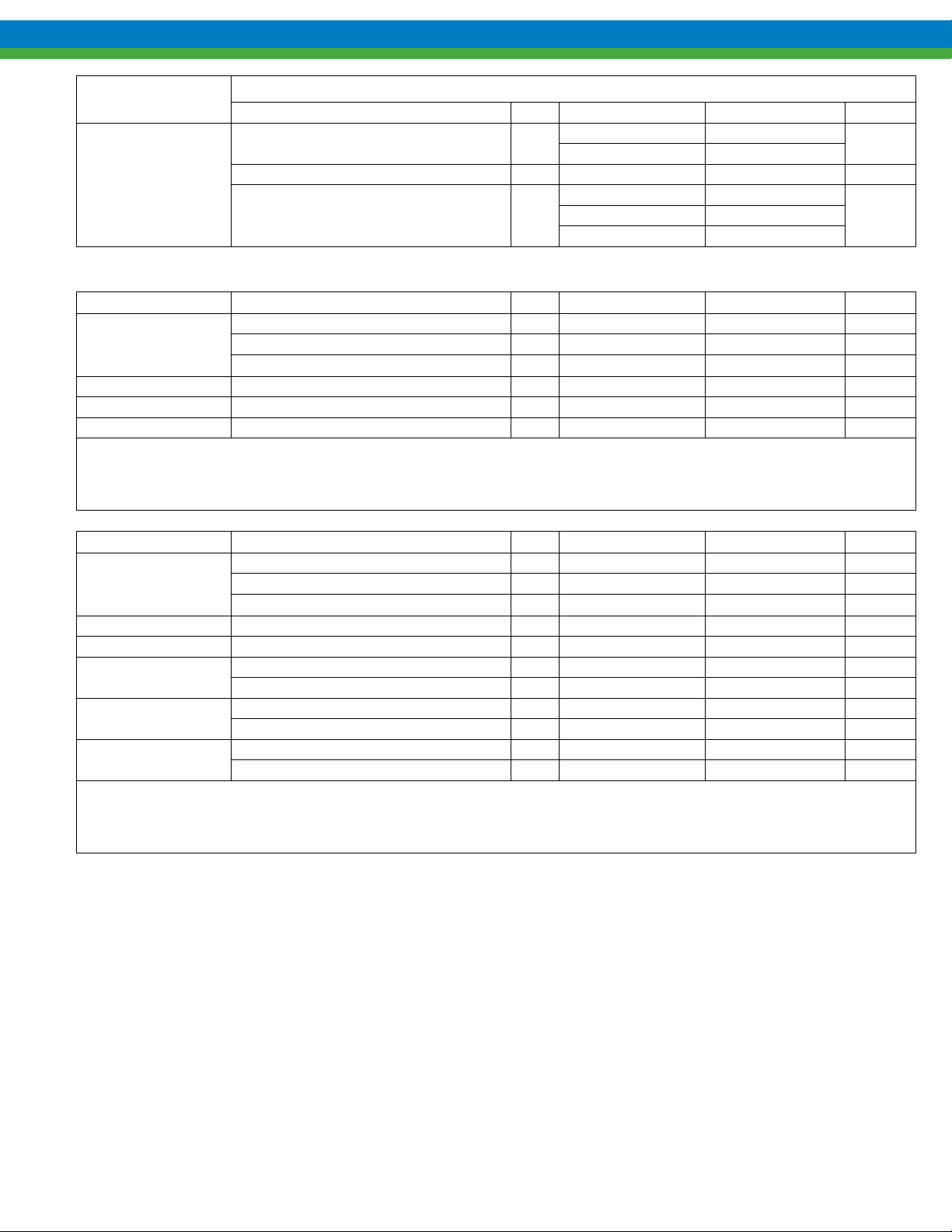
OPTIONS
Position 9
(FLUSH OPTION)
A
KOPKits
Kit # Description Item Part Number: Material Qty
E12XLx-LTE or
E12XBx-LTE
V
E
K
LTE Kit Reference:
Bearing Not Included
E12Xx(x) – O-Ring Material Code
Example: E12XLV-LTE
Kit # Description Item Part Number: Material Qty
E12Xxx-STD
L
B
V
E
K
STD Kit Reference:
Bearing Not Included
E12Xx(x) – O-Ring Material Code
Example: E12XLV-STD
(only part number affecting options shown here)
Description Item Part Number: Material Qty
Front cover with bearing flush
(match material selected for cover)
Drain plug for cover 34 NG990014-FTE ETFE 1
Drain plug o-ring (match o-ring
material selected for the pump)
Liner, Housing 11 NG220006-FTE ETFE 1
Gear Assembly, Drive 13 NG010022-FTE ETFE / ALA 1
Gear Assembly, Idler 12 NG010021-FTE ETFE / ALA 1
O-ring Cover 6 NG440137-VTA Viton A 1
O-ring Cover 6 NG440137-N0R EPDM 1
O-ring Cover 6 NG440137-KLZ Kalrez 1
Liner, Housing 11 NG220006-FTE ETFE 1
Gear Assembly, Drive 13 NG010022-FTE ETFE / ALA 1
Gear Assembly, Idler 12 NG010021-FTE ETFE / ALA 1
Bearing 10 NG080002-CBN Carbon -92 2
Bearing 10 NG080002-SIC Silicon Carbide 2
O-ring Cover 6 NG440137-VTA Viton A 1
O-ring Compression 9 NG440129-VTA Viton A 1
O-ring Cover 6 NG440137-N0R EPDM 1
O-ring Compression 9 NG440137-N0R EPDM 1
O-ring Cover 6 NG440137-KLZ Kalrez 1
O-ring Compression 9 NG440129-KLZ Kalrez 1
5
33
NG020005-FTE ETFE
NG020005-PPL Polypropylene
NG440012-VTA Viton A
W059100-N0R EPDM
NG440012-KLZ Kalrez
1
1
61
Page 68

Kit # Description Item Part Number: Material Qty
Liner, Housing 11 NG220006-FTE ETFE 1
Gear Assembly, Drive 13 NG010022-FTE ETFE / ALA 1
E12Xxx-PRO
L
B
V
E
K
PRO Kit Reference:
Bearing Not Included
E12Xx(x) – O-Ring Material Code
Example: E12XLV-PRO
Optional Kits:
Kit # Description Part Number: Material Qty
E12FXE
E12 Flg Adapt Kit
EPDM
Sub - Kit #
Gear Assembly, Idler 12 NG010021-FTE ETFE / ALA 1
Bolt 3 W770403-188 Stainless Steel 6
Washer 4 NG990018-188 Stainless Steel 6
Plate, Nut 28 NG990009-188 Stainless Steel 2
Bearing 10 NG080002-CBN Carbon -92 2
Bearing 10 NG080002-SIC Silicon Carbide 2
O-ring Cover 6 NG440137-VTA Viton A 1
O-ring Compression 9 NG440129-VTA Viton A 1
O-ring Cover 6 NG440137-N0R EPDM 1
O-ring Compression 9 NG440137-N0R EPDM 1
O-ring Cover 6 NG440137-KLZ Kalrez 1
O-ring Compression 9 NG440129-KLZ Kalrez 1
E12 FLG ADAPT .75-150#/DIN15-20 NG990034-PVD Carbon-Filled PVDF 2
E12 FLG RING .75-150#/DIN15-20 NG990035-188 Stainless Steel 2
GASKET, FLG, E12 .75-150# NG130004-TFE Teflon 2
GASKET, O-RING 2-124 NG440124-N0R EPDM 2
GASKET, O-RING 2-124 NG440124-N0R EPDM 2
E12F Common Parts
Kit # Description Part Number: Material Qty
E12 FLG ADAPT .75-150#/DIN15-20 NG990034-PVD Carbon-Filled PVDF 2
E12FXV
E12 Flg Adapt Kit
Viton A
E12 FLG RING .75-150#/DIN15-20 NG990035-188 Stainless Steel 2
GASKET, FLG, E12 .75-150# NG130004-TFE Teflon 2
GASKET, O-RING 2-124 NG440124-N0R EPDM 2
GASKET, O-RING 2-124 NG440124-VTA Viton A 2
Sub - Kit #
Kit # Description Part Number: Material Qty
E12 FLG ADAPT .75-150#/DIN15-20 NG990034-PVD Carbon-Filled PVDF 2
E12FXT
E12 Flg Adapt Kit
FEP
E12 FLG RING .75-150#/DIN15-20 NG990035-188 Stainless Steel 2
GASKET, FLG, E12 .75-150# NG130004-TFE Teflon 2
GASKET, O-RING 2-124 NG440124-N0R EPDM 2
GASKET, O-RING 2-124 NG440124-001 FEP Encapsulated 2
Sub - Kit #
E12F Common Parts
E12F Common Parts
62
Page 69

17. Parts Diagram and List, Eclipse Standard 25
63
Page 70

Eclipse Standard Pump Series Size 25
Consolidated Bill of Material – Eclipse Standard
Position 1,2,3,4 - Base Pump Material/Ports
(* Denotes recommended spares)
E25 Description Item Part Number:
Bolt 3 W770404-188 Stainless Steel 6
Washer 4 NG990018-188 Stainless Steel 6
Plate, Nut 28 NG990010-188 Stainless Steel 2
Cover, Front 5 NG020003-FTE ETFE 1
Plate, Reinforcement 35 NG120007-188 Stainless Steel 2
Bolt 16 W770426-188 Stainless Steel 8
Washer 17 NG990019-188 Stainless Steel 8
Kit, Flange Gaskets / O-rings NG450001-VTA Teflon/Viton 2
…….O-ring Gasket 38 NG440129-VTA Viton A 4 REF
…….O-ring Gasket NG440137-VTA Viton A 2 REF
Common Parts
F
…….Flange Gasket 31 NG130001-TFE Teflon 2 REF
Name Plate 1 NG550003-304 Stainless Steel 1
Drive Screw 2 W771000-188 Stainless Steel 2
Can, Containment 19 NG210006-FTE ETFE 1
Driven Magnet Assembly 21 NG200032-TEF Neo / ETFE 1
Drive Magnet 24 NG200036-STL Neo / Steel 1
Adapter, Spool 20 NG110009-ALU Aluminum 1
Base 32 NG970001-PET Polyester 1
Bolt 33 W770425-188 Stainless Steel 4
Plug, Drain 37 NG990014-FTE ETFE 1
Washer 34 NG990019-188 Stainless Steel 4
Housing, Center Flanged 14 NG040023-FTE ETFE 1
Position 4 Base Pump Material and Port
Connection
ETFE (F)
Material
Qty
Position 5 - Bearing Materials
Description Item Part Number: Material Qty
Common Parts
L
B
Liner, Housing* 11 NG220004-FTE ETFE 1
Gear Assembly, Drive * 13 NG010018-FTE ETFE / ALA 1
Gear Assembly, Idler * 12 NG010017-FTE ETFE / ALA 1
Bearing * 10 NG080003-CBN Carbon -92 2
Bearing * 10 NG080003-SIC Silicon Carbide 2
64
Page 71
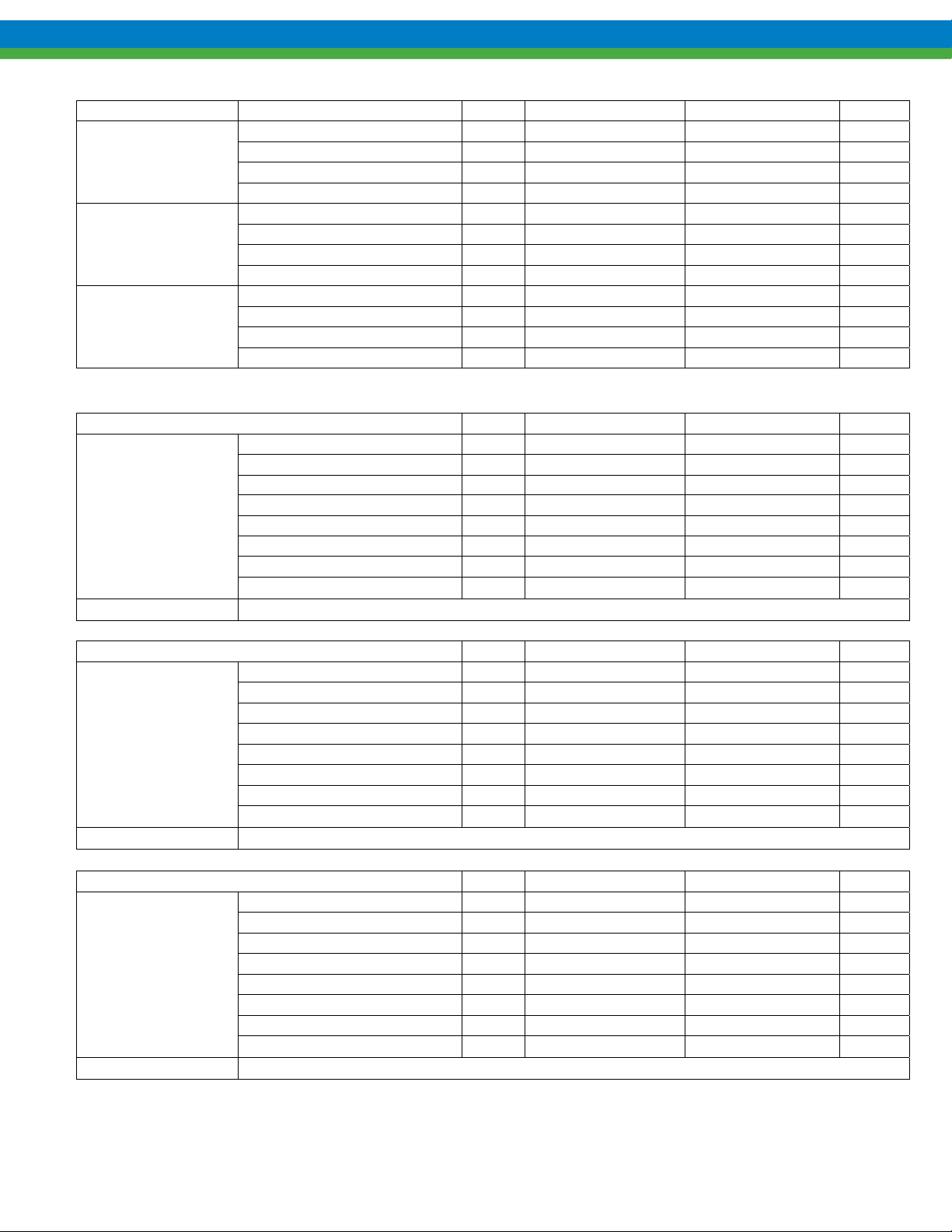
Position 6 - O-ring Material Selection
Description Item Part Number: Material Qty
V
E
K
O-ring Containment Can * 15 NG440158-VTA Viton A 1
O-ring Cover * 6 NG440147-VTA Viton A 1
O-ring Drain Plug * 36 NG440012-VTA Viton A 1
O-ring Compression * 9 NG440138-VTA Viton A 1
O-ring Containment Can * 15 NG440158-N0R EPDM 1
O-ring Cover * 6 NG440147-N0R EPDM 1
O-ring Drain Plug * 36 W059100-N0R EPDM 1
O-ring Compression * 9 NG440138-N0R EPDM 1
O-ring Containment Can * 15 NG440158-KLZ Kalrez 1
O-ring Cover * 6 NG440147-KLZ Kalrez 1
O-ring Drain Plug * 36 NG440012-KLZ Kalrez 1
O-ring Compression * 9 NG440138-KLZ Kalrez 1
Position 7 - NEMA C-Face and IEC B34 Metric Frame Magnetic Coupling Arrangement
56C NEMA frame components Item Part Number: Material Qty
Coupling Hub 25 NG940002-STL Steel 1
Adaptor, Motor 18 NG110006-PET Polyester 1
Set Screw 26 W771004-031 Steel 1
F
Motor Mount Kit # E25XXXF
143TC - 182C NEMA frame components Item Part Number: Material Qty
O
Motor Mount Kit # E25XXXO
Bolt 29 W770425-188 Stainless Steel 4
Washer 30 NG990019-188 Stainless Steel 4
Bolt 22 W770426-188 Stainless Steel 4
Washer 23 NG990019-188 Stainless Steel 4
Screw 27 W770021-188 Stainless Steel 4
Coupling Hub 25 NG940003-STL Steel 1
Adaptor, Motor 18 NG110006-PET Polyester 1
Set Screw 26 W771004-031 Steel 1
Bolt 29 W770425-188 Stainless Steel 4
Washer 30 NG990019-188 Stainless Steel 4
Bolt 22 W770426-188 Stainless Steel 4
Washer 23 NG990019-188 Stainless Steel 4
Screw 27 W770021-188 Stainless Steel 4
100/112 IEC B34 frame components Item Part Number: Material Qty
Coupling Hub 25A NG940006-STL Steel 1
Adaptor, Motor 18 NG110006-PET Polyester 1
Set Screw 26A NP991004-018 Steel 1
P
Motor Mount Kit # E25XXXP
Bolt 29A W770534-188 Stainless Steel 4
Washer 30A NP991018-188 Stainless Steel 4
Bolt 22 W770426-188 Stainless Steel 4
Washer 23 NG990019-188 Stainless Steel 4
Screw 27 W770021-188 Stainless Steel 4
65
Page 72

80 IEC B34 frame components Item Part Number: Material Qty
Coupling Hub 80 25A NG940005-STL Steel 1
Adaptor, Motor 26A NG110020-ALU Aluminum 1
Set Screw 26A NP991004-001 Steel 1
K
Motor Mount Kit # E25XXXK
90 IEC B34 frame components Item Part Number: Material Qty
L
Motor Mount Kit # E25XXXL
Bolt 29A NP999121-188 Stainless Steel 4
Washer 30A NP991017-188 Stainless Steel 4
Bolt 22 W770426-188 Stainless Steel 4
Washer 23 NG990019-188 Stainless Steel 4
Screw 27 W770021-188 Stainless Steel 4
Coupling Hub 90 25A NG940013-STL Steel 1
Adaptor 26A NG110020-ALU Aluminum 1
Set Screw 26A NP991004-018 Steel 1
Bolt 29A NP999004-188 Stainless Steel 4
Washer 30A NP991018-188 Stainless Steel 4
Bolt 22 W770426-188 Stainless Steel 4
Washer 23 NG990019-188 Stainless Steel 4
Screw 27 W770021-188 Stainless Steel 4
OPTIONS
Position 9
(FLUSH OPTION)
A
(only part number affecting options shown here)
Description Item Part Number: Material Qty
Front cover with bearing flush
(match selected pump
material)
Drain plug for cover 37 NG990014-FTE ETFE 1
Drain plug o-ring (match o-
ring material selected for the
pump)
5
36
NG020006-FTE ETFE
NG020006-PPL PPL
NG440012-VTA Viton A
W059100-N0R EPDM
NG440012-KLZ Kalrez
KOPKits
Kit # Description Item Part Number: Material Qty
E25XLx-LTE or
E25XBx-LTE
V
E
K
LTE Kit Reference:
Bearing Not Included
E25Xx(x) – O-Ring Material Code
Example: E25XLV-LTE
Liner, Housing 11 NG220004-FTE ETFE 1
Gear Assembly, Drive 13 NG010018-FTE ETFE / ALA 1
Gear Assembly, Idler 12 NG010017-FTE ETFE / ALA 1
O-ring Cover 6 NG440147-VTA Viton A 1
O-ring Cover 6 NG440147-N0R EPDM 1
O-ring Cover 6 NG440147-KLZ Kalrez 1
1
1
66
Page 73

Kit #
Liner, Housing 11 NG220004-FTE ETFE 1
E25Xxx-STD
L
B
V
E
K
STD Kit Reference:
E25X(x)x – Bearing Material Code
E25Xx(x) – O-Ring Material Code
Example: E25XLV-STD
Gear Assembly, Drive 13 NG010018-FTE ETFE / ALA 1
Gear Assembly, Idler 12 NG010017-FTE ETFE / ALA 1
Bearing 10 NG080003-CBN Carbon -92 2
Bearing 10 NG080003-SIC Silicon Carbide 2
O-ring Cover 6 NG440147-VTA Viton A 1
O-ring Compression 9 NG440138-VTA Viton A 1
O-ring Cover 6 NG440147-N0R EPDM 1
O-ring Compression 9 NG440138-N0R EPDM 1
O-ring Cover 6 NG440147-KLZ Kalrez 1
O-ring Compression 9 NG440138-KLZ Kalrez 1
Description Item Part Number: Material Qty
Kit #
Liner, Housing 11 NG220004-FTE ETFE 1
Gear Assembly, Drive 13 NG010018-FTE ETFE / ALA 1
E25Xxx-PRO
L
B
V
E
K
PRO Kit Reference:
E25X(x)x – Bearing Material Code
E25Xx(x) – O-Ring Material Code
Example: E25XLV-PRO
Gear Assembly, Idler 12 NG010017-FTE ETFE / ALA 1
Bolt 3 W770404-188 Stainless Steel 6
Washer 4 NG990018-188 Stainless Steel 6
Plate, Nut 28 NG990010-188 Stainless Steel 2
Bearing 10 NG080003-CBN Carbon -92 2
Bearing 10 NG080003-SIC Silicon Carbide 2
O-ring Cover 6 NG440147-VTA Viton A 1
O-ring Compression 9 NG440138-VTA Viton A 1
O-ring Cover 6 NG440147-N0R EPDM 1
O-ring Compression 9 NG440138-N0R EPDM 1
O-ring Cover 6 NG440147-KLZ Kalrez 1
O-ring Compression 9 NG440138-KLZ Kalrez 1
Description Item Part Number: Material Qty
67
Page 74

18. Parts Diagram and List, Eclipse Standard 75
68
Page 75

Eclipse Standard Series Size 75
Consolidated Bill of Material – Eclipse Standard
Position 1,2,3,4 - Base Pump Material/Ports
(* Denotes recommended spares)
E75 Description Item Part Number: Material Qty
Bolt 3 W770428-188 Stainless Steel 6
Washer 4 NG990019-188 Stainless Steel 6
Plate, Nut 28 NG990011-188 Stainless Steel 2
Cover, Front 5 NG020004-FTE ETFE 1
Plate, Reinforcement 35 NG120008-188 Stainless Steel 2
Bolt 16 W770428-188 Stainless Steel 8
Washer 17 NG990019-188 Stainless Steel 8
KIT, Flange Gaskets / O-rings 31 NG450002-VTA Teflon/Viton A 2
…….O-ring Gasket 38 NG440138-001 Viton A 4 REF
…….O-ring Gasket NG440150-VTA Viton A 2 REF
Common Parts
F
…….Flange Gaskets 31 NG130002-TFE Teflon 2 REF
Name Plate 1 NG550004-304 Stainless Steel 1
Drive Screw 2 W771000-188 Stainless Steel 2
Can, Containment 19 NG210007-FTE ETFE 1
Driven Magnet Assembly 21 NG200033-TEF Neo / ETFE 1
Drive Magnet 24 NG200037-STL Neo / Steel 1
Adapter, Spool 20 NG110011-ALU Aluminum 1
Base 32 NG970001-PET Polyester 1
Bolt 33 W770425-188 Stainless Steel 4
Drain Plug 37 NG990014-FTE ETFE 1
Washer 34 NG990019-188 Stainless Steel 4
Housing, Center Flanged 14 NG040024-FTE ETFE 1
Position 4 Base Pump Material and Port
Connection
ETFE (F)
Position 5 - Bearing Materials
Description Item Part Number: Material Qty
Liner, Housing * 11 NG220005-FTE ETFE 1
Common Parts
L
B
Gear Assembly, Drive * 13 NG010020-FTE ETFE / ALA 1
Gear Assembly, Idler * 12 NG010019-FTE ETFE / ALA 1
Bearing * 10 NG080004-CBN Carbon -92 2
Bearing * 10 NG080004-SIC Silicon Carbide 2
69
Page 76

Position 6 - O-ring Material Selection
Description Item Part Number: Material Qty
O-ring Containment Can * 15 NG440163-VTA Viton A 1
V
E
K
O-ring Cover * 6 NG440155-VTA Viton A 1
O-ring Drain Plug * 36 NG440012-VTA Viton A 1
O-ring Compression * 9 NG440152-VTA Viton A 1
O-ring Containment Can * 15 NG440163-N0R EPDM 1
O-ring Cover * 6 NG440155-N0R EPDM 1
O-ring Drain Plug * 36 W059100-N0R EPDM 1
O-ring Compression * 9 NG440152-N0R EPDM 1
O-ring Containment Can * 15 NG440163-KLZ Kalrez 1
O-ring Cover * 6 NG440155-KLZ Kalrez 1
O-ring Drain Plug * 36 NG440012-KLZ Kalrez 1
O-ring Compression * 9 NG440152-KLZ Kalrez 1
Position 7 - NEMA C-Face and IEC B14/B34 Metric Frame Magnetic Coupling Arrangement
80 IEC B14/B34 frame components
Coupling Hub 80 25A NG940005-STL Steel 1
Adaptor, Motor 26A NG110024-ALU Aluminum 1
Set Screw 26A NP991004-001 Steel 1
K
Motor Mount Kit # E75XXXK
Bolt 29A NP999121-188 Stainless Steel 4
Washer 30A NP991017-188 Stainless Steel 4
Bolt 22 W770427-188 Stainless Steel 4
Washer 23 NG990019-188 Stainless Steel 4
Screw 27 W770021-188 Stainless Steel 4
Item Part Number: Material Qty
90 IEC B14/B34 frame components Item Part Number: Material Qty
Coupling Hub 90 25A NG940013-STL Steel 1
Adaptor, Motor 26A NG110024-ALU Aluminum 1
Set Screw 26A NP991004-018 Steel 1
L
Motor Mount Kit # E75XXXL
143TC - 182C NEMA frame components
O
Motor Mount Kit # E75XXXO
Bolt 29A NP999004-188 Stainless Steel 4
Washers 30A NP991018-188 Stainless Steel 4
Bolt 22 W770427-188 Stainless Steel 4
Washer 23 NG990019-188 Stainless Steel 4
Screw 27 W770021-188 Stainless Steel 4
Item Part Number: Material Qty
Coupling Hub 25A NG940003-STL Steel 1
Set Screw 26A W771004-031 Steel 1
Bolt 29A W770425-188 Stainless Steel 4
Washer 30A NG990019-188 Stainless Steel 4
Bolt 22 W770428-188 Stainless Steel 4
Washer 23 NG990019-188 Stainless Steel 4
Adapter, Motor 18 NG110008-PET Polyester 1
Screw 27 W770021-188 Stainless Steel 4
70
Page 77

182TC - 184TC NEMA frame components Item Part Number: Material Qty
Coupling Hub 25 NG940007-STL Steel 1
Set Screw 26 W771004-046 Steel 1
Bolt 29 W770438-188 Stainless Steel 4
R
Motor Mount Kit # E75XXXR
Washer 30 W771035-188 Stainless Steel 4
Bolt 22 W770428-188 Stainless Steel 4
Washer 23 NG990019-188 Stainless Steel 4
Adapter, Motor 18 NG110008-PET Polyester 1
Screw 27 W770021-188 Stainless Steel 4
213TC - 215TC NEMA frame components
Coupling Hub 25B NG940015-000 Steel 1
Set Screw 26B W771004-041 Steel 1
Adapter, Motor 18 NG110008-PET Polyester 2
Mate, Motor Adaptor 18A NG110023-STL Steel 1
W
Motor Mount Kit # E75XXXW
254TC - 256TC NEMA frame components
Z
Motor Mount Kit # E75XXXZ
Bolt (motor) 29 W770438-18 8 Stainless Steel 4
Washer (motor) 30 W771035-188 Stainless Steel 4
Bolt – spool 22 W770062-188 Stainless Steel 4
Washer – spool 23 NG990019-188 Stainless Steel 4
Screw 27 W770021-188 Stainless Steel 4
Coupling Hub 25B NG940012-STL Steel 1
Set Screw 26B W771004-041 Steel 1
Adapter, Motor 18 NG110008-PET Polyester 2
Mate, Motor Adaptor 18A NG110023-STL Steel 1
Bolt 29B W770438-188 Stainless Steel 4
Washer 30B W771035-188 Stainless Steel 4
Bolt – spool 22 W770062-188 Stainless Steel 4
Washer – spool 23 NG990019-188 Stainless Steel 4
Screw 27 W770021-188 Stainless Steel 4
Item Part Number: Material Qty
Item Part Number: Material Qty
100/112 IEC B14/B34 frame components Item Part Number: Material Qty
Coupling Hub 25B NG940006-STL Steel 1
Set Screw 26B NP991004-018 Steel 1
Bolt 29B W770534-188 Stainless Steel 4
P
Motor Mount Kit # E75XXXP
Washer 30B NP991018-188 Stainless Steel 4
Bolt 22 W770428-188 Stainless Steel 4
Washer 23 NG990019-188 Stainless Steel 4
Adapter, Motor 18 NG110008-PET Polyester 1
Screw 27 W770021-188 Stainless Steel 4
71
Page 78

132 IEC B14/B34 frame components Item Part Number: Material Qty
Coupling Hub 25B NG940014-STL Steel 1
Set Screw 26B NP992570-188 Steel 1
Bolt 29B W770547-STL Stainless Steel 4
V
Motor Mount Kit # E75XXXV
Washer 30B NP991018-188 Stainless Steel 4
Bolt – spool 22 W770428-188 Stainless Steel 4
Adaptor, 132 Motor 18 NG110022-ALU Aluminum 1
Washer – spool 23 NG990019-188 Stainless Steel 4
Screw 27 W770021-188 Stainless Steel 4
OPTIONS
Position 9
A
(FLUSH OPTION)
(only part number affecting options shown here)
Front cover with bearing flush
(match selected pump material)
Drain plug for cover 37 NG990014-FTE ETFE 1
Drain plug o-ring (match o-ring
material selected for the pump)
Description Item Part Number: Material Qty
5
36
NG020007-FTE ETFE 1
NG020007-PPL PPL 1
NG440012-VTA Viton A 1
W059100-N0R EPDM 1
NG440012-KLZ Kalrez 1
KOPKits
Kit # Description Item Part Number: Material Qty
E75XLx-LTE or
E75XBx-LTE
V
E
K
LTE Kit Reference:
Bearing Not Included
E75Xx(x) – O-Ring Material Code
Example: E75XLV-LTE
Kit # Description Item Part Number: Material Qty
E75Xxx-STD
L
B
V
E
K
STD Kit Reference:
E75X(x)x – Bearing Material Code
E75Xx(x) – O-Ring Material Code
Example: E75XLV-STD
Liner, Housing 11 NG220005-FTE ETFE 1
Gear Assembly, Drive 13 NG010020-FTE ETFE/ALA 1
Gear Assembly, Idler 12 NG010019-FTE ETFE/ALA 1
O-ring Cover 6 NG440155-VTA Viton A 1
O-ring Cover 6 NG440155-N0R EPDM 1
O-ring Cover 6 NG440155-KLZ Kalrez 1
Liner, Housing 11 NG220005-FTE ETFE 1
Gear Assembly, Drive 13 NG010020-FTE ETFE/ALA 1
Gear Assembly, Idler 12 NG010019-FTE ETFE/ALA 1
Bearing 10 NG080004-CBN Carbon -92 2
Bearing 10 NG080004-SIC Silicon Carbide 2
O-ring Cover 6 NG440155-VTA Viton A 1
O-ring Compression 9 NG440152-VTA Viton A 1
O-ring Cover 6 NG440155-N0R EPDM 1
O-ring Compression 9 NG440152-N0R EPDM 1
O-ring Cover 6 NG440155-KLZ Kalrez 1
O-ring Compression 9 NG440152-KLZ Kalrez 1
72
Page 79

Kit # Description Item Part Number: Material Qty
Liner, Housing 11 NG220005-FTE ETFE 1
Gear Assembly, Drive 13 NG010020-FTE ETFE/ALA 1
E75Xxx-PRO
L
B
V
E
K
PRO Kit Reference:
E75X(x)x – Bearing Material Code
E75Xx(x) – O-Ring Material Code
Example: E75XLV-PRO
Gear Assembly, Idler 12 NG010019-FTE ETFE/ALA 1
Bolt 3 W770428-188 Stainless Steel 6
Washer 4 NG990019-188 Stainless Steel 6
Plate, Nut 28 NG990011-188 Stainless Steel 2
Bearing 10 NG080004-CBN Carbon -92 2
Bearing 10 NG080004-SIC Silicon Carbide 2
O-ring Cover 6 NG440155-VTA Viton A 1
O-ring Compression 9 NG440152-VTA Viton A 1
O-ring Cover 6 NG440155-N0R EPDM 1
O-ring Compression 9 NG440152-N0R EPDM 1
O-ring Cover 6 NG440155-KLZ Kalrez 1
O-ring Compression 9 NG440152-KLZ Kalrez 1
Note, 21 in quantity column denotes a quantity of 2 if the 9th position is option “A” (Bearing Flush)
73
Page 80

19. Parts Diagram and List, Eclipse Standard 125
74
Page 81

Eclipse Standard Series Size 125
Consolidated Bill of Material – Eclipse Standard
Position 1,2,3,4 - Base Pump Material/Ports
(* Denotes recommended spares)
E125 Description Item Part Number: Material Qty
Bolt 3 W770428-188 Stainless Steel 6
Washer 4 NG990019-188 Stainless Steel 6
Plate, Nut 28 NG990011-188 Stainless Steel 2
Cover, Front 5 NG020004-FTE ETFE 1
Plate, Reinforcement 35 NG120008-188 Stainless Steel 2
Bolt 16 W770428-188 Stainless Steel 8
Washer 17 NG990019-188 Stainless Steel 8
Kit, Flange Gaskets / O-rings 31 NG450002-0 01 Teflon/Viton A 2
…….O-ring Gasket 38 NG440138-VTA Viton A 4 REF
…….O-ring Gasket NG440150-VTA Viton A 2 REF
Common Parts
F
…….Flange Gaskets 31 NG130002-TFE Teflon 2 REF
Name Plate 1 NG550004-304 Stainless Steel 1
Drive Screw 2 W771000-188 Stainless Steel 2
Containment Can 19 NG210007-FTE ETFE 1
Driven Magnet Assembly 21 NG200033-TEF Neo / ETFE 1
Drive Magnet 24 NG200037-STL Neo / Steel 1
Adapter, Spool 20 NG110011-ALU Aluminum 1
Bolt (base) 33 W770425-188 Stainless Steel 4
Washer (spool) 34 NG990019-188 Stainless Steel 4
Base 32 NG970001-PET Polyester 1
Plug, Drain 37 NG990014-FTE ETFE 1
Housing, Center Flanged 14 NG040024-FTE ETFE 1
Position 4 Base Pump Material and Port Connection
ETFE (F)
Position 5 - Bearing Materials
Description Item Part Number: Material Qty
Liner, Housing * 11 NG220007-FTE ETFE 1
Common Parts
L
B
Gear Assembly, Drive * 13 NG010025-FTE ETFE / ALA 1
Gear Assembly, Idler * 12 NG010024-FTE ETFE / ALA 1
Bearing * 10 NG080007-CBN Carbon -92 2
Bearing * 10 NG080007-SIC Silicon Carbide 2
75
Page 82

Position 6 - O-ring Material Selection
Description Item Part Number: Material Qty
O-ring Containment Can * 15 NG440163-VTA Viton A 1
V
E
K
O-ring Cover * 6 NG440155-VTA Viton A 1
O-ring Drain Plug * 36 NG440012-VTA Viton A 1
O-ring Compression * 9 NG440152-VTA Viton A 1
O-ring Containment Can * 15 NG440163-N0R EPDM 1
O-ring Cover * 6 NG440155-N0R EPDM 1
O-ring Drain Plug * 36 W059100-N0R EPDM 1
O-ring Compression * 9 NG440152-N0R EPDM 1
O-ring Containment Can * 15 NG440163-KLZ Kalrez 1
O-ring Cover * 6 NG440155-KLZ Kalrez 1
O-ring Drain Plug * 36 NG440012-KLZ Kalrez 1
O-ring Compression * 9 NG440152-KLZ Kalrez 1
Position 7 - NEMA C-Face and IEC B14 Metric Frame Magnetic Coupling Arrangement
143TC - 182C NEMA frame components Item Part Number: Material Qty
Coupling Hub 25A NG940003-STL Steel 1
Set Screw 26A W771004-031 Steel 1
Bolt 29A W770425-188 Stainless Steel 4
O
Motor Mount Kit # E125XXXO
Washer 30A NG990019-188 Stainless Steel 4
Bolt 22 W770428-188 Stainless Steel 4
Washer 23 NG990019-188 Stainless Steel 4
Adapter, Motor 18 NG110008-PET Polyester 1
Screw 27 W770021-188 Stainless Steel 4
182TC - 184TC NEMA frame components Item Part Number: Material Qty
Coupling Hub 25 NG940007-STL Steel 1
Set Screw 26 W771004-046 Steel 1
Bolt (motor) 29 W770438-188 Stainless Steel 4
R
Motor Mount Kit # E125XXXR
Washer (motor) 30 W771035-188 Stainless Steel 4
Bolt (spool) 22 W770428-188 Stainless Steel 4
Adapter, Motor 18 NG110008-PET Polyester 1
Washer (base) 23 NG990019-188 Stainless Steel 4
Screw 27 W770021-188 Stainless Steel 4
213TC - 215TC NEMA frame components Item Part Number: Material Qty
Coupling Hub 25B NG940015-000 Steel 1
Set Screw 26B W771004-041 Steel 1
Adapter, Motor 18 NG110008-PET Polyester 2
Mate, Motor Adaptor 18A NG110023-STL Steel 1
W
Motor Mount Kit # E125XXXW
Bolt (motor) 29 W770438-188 Stainless Steel 4
Washer (motor) 30 W771035-188 Stainless Steel 4
Bolt – spool 22 W770062-188 Stainless Steel 4
Washer - spool 23 NG990019-188 Stainless Steel 4
Screw 27 W770021-188 Stainless Steel 4
76
Page 83

254TC - 256TC NEMA frame components Item Part Number: Material Qty
Coupling Hub 25B NG940012-STL Steel 1
Set Screw 26B W771004-041 Steel 1
Adapter, Motor 18 NG110008-PET Polyester 2
Mate, Motor Adaptor 18A NG110023-STL Steel 1
Z
Motor Mount Kit # E125XXXZ
100/112 IEC B14 frame components Item Part Number: Material Qty
P
Motor Mount Kit # E125XXXP
Bolt 29B W770438-188 Stainless Steel 4
Washer 30B W771035-188 Stainless Steel 4
Bolt – spool 22 W770062-188 Stainless Steel 4
Washer - spool 23 NG990019-188 Stainless Steel 4
Screw 27 W770021-188 Stainless Steel 4
Coupling Hub 25B NG940006-STL Steel 1
Set Screw 26B NP991004-018 Steel 1
Bolt – motor 29B W770534-188 Stainless Steel 4
Washer - motor 30B NP991018-188 Stainless Steel 4
Bolt – spool 22 W770438-188 Stainless Steel 4
Adapter, Motor 18 NG110008-PET Polyester 1
Washer - base 23 NG990019-188 Stainless Steel 4
Screw 27 W770021-188 Stainless Steel 4
132 IEC B14 frame components Item Part Number: Material Qty
Coupling Hub 25B NG940014-STL Steel 1
Set Screw 26B NP992570-188 Steel 1
Bolt 29B W770547-STL Stainless Steel 4
V
Motor Mount Kit # E125XXXV
Washer 30B NP991018-188 Stainless Steel 4
Bolt – spool 22 W770428-188 Stainless Steel 4
Adaptor, 132 Motor 18 NG110022-ALU Aluminum 1
Washer - spool 23 NG990019-188 Stainless Steel 4
Screw 27 W770021-188 Stainless Steel 4
OPTIONS
Position 9
(FLUSH OPTION)
A
(only part number affecting options shown here)
Description Item Part Number: Material Qty
Front cover with bearing
flush (match selected pump
material)
Drain plug for cover 37 NG990014-FTE ETFE 1
Drain plug o-ring (match o-
ring material selected for the
pump)
5
36
NG020007-FTE ETFE
NG020007-PPL PPL
NG440012-VTA Viton A
W059100-N0R EPDM
NG440012-KLZ Kalrez
1
1
77
Page 84

KOPKits
Kit # Description Item Part Number: Material Qty
E125XLx-LTE or
E125XBx-LTE
V
E
K
LTE Kit Reference:
Bearing Not Included
E125Xx(x) – O-Ring Material Code
Example: E125XLV-LTE
Liner, Housing 11 NG220007-FTE ETFE 1
Gear Assembly, Drive 13 NG010025-FTE ETFE / ALA 1
Gear Assembly, Idler 12 NG010024-FTE ETFE / ALA 1
O-ring Cover 6 NG440155-VTA Viton A 1
O-ring Cover 6 NG440155-N0R EPDM 1
O-ring Cover 6 NG440155-KLZ Kalrez 1
Kit #
Liner, Housing 11 NG220007-FTE ETFE 1
E125Xxx-STD
L
B
V
E
K
STD Kit Reference:
E125X(x)x – Bearing Material Code
E125Xx(x) – O-Ring Material Code
Example: E125XLV-STD
Kit #
E125Xxx-PRO
L
B
V
E
K
STD Kit Reference:
E125X(x)x – Bearing Material Code
E125Xx(x) – O-Ring Material Code
Example: E125XLV-STD
Gear Assembly, Drive 13 NG010025-FTE ETFE / ALA 1
Gear Assembly, Idler 12 NG010024-FTE ETFE / ALA 1
Bearing 10 NG080007-CBN Carbon -92 2
Bearing 10 NG080007-SIC Silicon Carbide 2
O-ring Cover 6 NG440155-VTA Viton A 1
O-ring Compression 9 NG440155-VTA Viton A 1
O-ring Cover 6 NG440155-N0R EPDM 1
O-ring Compression 9 NG440155-N0R EPDM 1
O-ring Cover 6 NG440155-KLZ Kalrez 1
O-ring Compression 9 NG440155-KLZ Kalrez 1
Liner, Housing 11 NG220007-FTE ETFE 1
Gear Assembly, Drive 13 NG010025-FTE ETFE / ALA 1
Gear Assembly, Idler 12 NG010024-FTE ETFE / ALA 1
Bolt 3 W770428-188 Stainless Steel 6
Washer 4 NG990019-188 Stainless Steel 6
Plate, Nut 28 NG990011-188 Stainless Steel 2
Bearing 10 NG080007-CBN Carbon -92 2
Bearing 10 NG080007-SIC Silicon Carbide 2
O-ring Cover 6 NG440155-VTA Viton A 1
O-ring Compression 9 NG440155-VTA Viton A 1
O-ring Cover 6 NG440155-N0R EPDM 1
O-ring Compression 9 NG440155-N0R EPDM 1
O-ring Cover 6 NG440155-KLZ Kalrez 1
O-ring Compression 9 NG440155-KLZ Kalrez 1
Description Item Part Number: Material Qty
Description Item Part Number: Material Qty
78
Page 85

20. Parts Diagram and List, Eclipse Hypo 02
79
Page 86

Eclipse Hypo Pump Series Size 02
Consolidated Bill of Material – Eclipse Hypo
Position 5 Base Pump Material
Position 1,2,3,4,5 - Base Pump Material/Ports
(* Denotes recommended spares) PVDF
EH02 Description Item Part Number: Material Qty
Screw 3 W770904-188 Stainless Steel 6
Washer 4 W771006-188 Stainless Steel 6
Screw 7 W770274-188 Stainless Steel 2
Name Plate 1 NG550003-304 Stainless Steel 1
Can, Containment 19 NG210004-PVD Carbon-filled PVDF 1
Driven Magnet Assembly 21 NG200030-TEF Neo / ETFE 1
Common Parts
K
M
Drive Magnet 24 NG200034-STL Neo / Steel 1
Plate, Cover Reinforcement 5A NG120011-188 Stainless Steel 1
Adapter, Spool 20 NG110010-PET Polyester 1
Adapter, Can 18 NG110012-PET Polyester 1
Bolt 16 W770403-188 Stainless Steel 8
Washer 17 NG990018-188 Stainless Steel 8
Plug, Drain 32 NG990014-FTE ETFE 1
Cover, Front 5 NG020001-PVD Carbon-filled PVDF 1
Housing, Center FNPT
Housing, Center FBSPT NG040020-PVD Carbon-filled PVDF
and Port Connection
(K) or (M)
14
NG040019-PVD Carbon-filled PVDF
Position 6 - Bearing Materials
Description Item Part Number: Material Qty
Liner, Housing * 11 NG220002-FTE ETFE 1
Common Parts
B
Gear Assembly, Drive * 13 NG010014-FTE ETFE / ALA 1
Gear Assembly, Idler * 12 NG010013-FTE ETFE / ALA 1
Bearing *
10
NG080001-SIC Silicon Carbide
1
2
Position 7 - O-ring Material Selection
Description Item Part Number: Material Qty
O-ring Containment Can * 15 NG440029-VTA Viton A 1
V
O-ring Cover * 6 NG440029-VTA Viton A 1
O-ring Compression * 9 NG440020-VTA Viton A 1
O-ring Drain Plug * NG440012-VTA Viton A 1
Position 8 - NEMA C-Face and IEC B34 Metric Frame Magnetic Coupling Arrangement
56C NEMA frame components Item Part Number: Material Qty
Coupling Hub 25 NG940002-STL Steel 1
Set Screw 26 W771004-031 Steel 1
F
Motor Mount Kit # E02XXXF
Bolt 22 W770425-188 Stainless Steel 4
Washer 23 NG990019-188 Stainless Steel 4
Screw 27 W770021-188 Stainless Steel 4
80
Page 87

63 IEC B34 frame components
Coupling Hub 25A NG940004-STL Steel 1
Set Screw 26A NP991004-017 Steel 1
Adapter, Motor 31 NG110005-PET Polyester 1
H
Motor Mount Kit # E02XXXH
Bolt 29 NP990418-188 Stainless Steel 4
Washer 30 NP991016-188 Stainless Steel 4
Bolt 22 W770426-188 Stainless Steel 4
Washer 23 NG990019-188 Stainless Steel 4
Screw 27 W770021-188 Stainless Steel 4
Item Part Number: Material Qty
71 IEC B34 frame components
Coupling Hub 25A NG940011-STL Steel 1
Set Screw 26A NG990027-188 Steel 1
Adapter, Motor 31 NG110019-ALU Aluminum 1
J
Motor Mount Kit # E02XXXJ
80 IEC B34 frame components
K
Motor Mount Kit # E02XXXK
Bolt 29 W770546-188 Stainless Steel 4
Bolt 22 W770426-188 Stainless Steel 4
Washer 23 NG990019-188 Stainless Steel 4
Screw 27 W770021-188 Stainless Steel 4
Coupling Hub 25B NG940005-STL Steel 1
Set Screw 26B NP991004-001 Steel 1
Adapter, Motor 31 NG110005-PET Polyester 1
Bolt 29A W770546-188 Stainless Steel 4
Washer 30A NP991017-188 Stainless Steel 4
Bolt 22 W770426-188 Stainless Steel 4
Washer 23 NG990019-188 Stainless Steel 4
Screw 27 W770021-188 Stainless Steel 4
Item Part Number: Material Qty
Item Part Number: Material Qty
81
Page 88

KOPKits
Kit # Description Item Part Number: Material Qty
Liner, Housing 11 NG220002-FTE ETFE 1
EH02XBV-LTE
Kit # Description Item Part Number: Material Qty
EH02XBV-STD
Gear Assembly, Drive 13 NG010014-FTE ETFE / ALA 1
Gear Assembly, Idler 12 NG010013-FTE ETFE / ALA 1
O-ring Cover 15 NG440029-VTA Viton A 1
Bearing 10 NG080001-SIC Silicon Carbide 2
Liner, Housing 11 NG220002-FTE ETFE 1
Gear Assembly, Drive 13 NG010014-FTE ETFE / ALA 1
Gear Assembly, Idler 12 NG010013-FTE ETFE / ALA 1
O-ring Cover 15 NG440029-VTA Viton A 1
O-ring Compression 9 NG440020-VTA Viton A 1
Kit #
EH02XBV-PRO
Bearing 10 NG080001-SIC Silicon Carbide 2
Liner, Housing 11 NG220002-FTE ETFE 1
Gear Assembly, Drive 13 NG010014-FTE ETFE / ALA 1
Gear Assembly, Idler 12 NG010013-FTE ETFE / ALA 1
O-ring Cover 15 NG440029-VTA Viton A 1
O-ring Compression 9 NG440020-VTA Viton A 1
Screw 3 W777904-188 Stainless Steel 6
Washer 4 W771006-188 Stainless Steel 6
Plate, Cover Reinforcement 5A NG120011-188 Stainless Steel 1
Description Item Part Number: Material Qty
82
Page 89

21. Parts Diagram and List, Eclipse Hypo 05
83
Page 90

Eclipse Hypo Pump Series Size 05
Consolidated Bill of Material – Eclipse Hypo
Position 5 Base Pump Material
Position 1,2,3,4,5 - Base Pump Material/Ports
(* Denotes recommended spares) PVDF
EH05 Description Item Part Number: Material Qty
Bolt 3 W770404-188 Stainless Steel 6
Washer 4 NG990018-188 Stainless Steel 6
Plate, Nut 28 NG990009-188 Stainless Steel 2
Cover, Front 5 NG020002-PVD Carbon-filled PVDF 1
Bolt 16 W770403-188 Stainless Steel 8
Washer 17 NG990018-188 Stainless Steel 8
Name Plate 1 NG550003-304 Stainless Steel 1
Common Parts
K
M
Drive Screw 2 W771000-188 Stainless Steel 2
Can, Containment 19 NG210005-PVD Carbon-filled PVDF 1
Driven Magnet Assembly 21 NG200031-TEF Neo / ETFE 1
Drive Magnet 24 NG200035-STL Neo / Steel 1
Plate, Cover Reinforcement 5A NG120012-188 Stainless Steel 1
Adapter, Spool 20 NG110010-PET Polyester 1
Plug, Drain 34 NG990014-FTE ETFE 1
Plate, Reinforcement 32 NG120006-188 Stainless Steel 2
Housing, Center FNPT
Housing, Center FBSPT NG040022-PVD Carbon-filled PVDF
and Port Connection
(K) or (M)
14
NG040021-PVD Carbon-filled PVDF
1
Position 6 - Bearing Materials
Description Item Part Number: Material Qty
Liner, Housing * 11 NG220003-FTE ETFE 1
Common Parts
B
Gear Assembly, Drive * 13 NG010016-FTE ETFE / ALA 1
Gear Assembly, Idler * 12 NG010015-FTE ETFE / ALA 1
Bearing * 10 NG080002-SIC Silicon Carbide 2
Position 7 - O-ring Material Selection
Description Item Part Number: Material Qty
O-ring Containment Can * 15 NG440154-VTA Viton A 1
V
O-ring Cover * 6 NG440137-VTA Viton A 1
O-ring Drain Plug * 33 NG440012-VTA Viton A 1
O-ring Compression * 9 NG440129-VTA Viton A 1
Position 8 - NEMA C-Face and IEC B34 Metric Frame Magnetic Coupling Arrangement
56C NEMA frame components
Coupling Hub 25 NG940002-STL Steel 1
Set Screw 26 W771004-031 Steel 1
F
Motor Mount Kit # E05XXXF
Bolt 22 W770425-188 Stainless Steel 4
Washer 23 NG990019-188 Stainless Steel 4
Screw 27 W770021-188 Stainless Steel 4
Item Part Number: Material Qty
84
Page 91

143TC - 182C NEMA frame components
Coupling Hub 25 NG940003-STL Steel 1
Set Screw 26 W771004-031 Steel 1
O
Motor Mount Kit # E05XXXO
Bolt 22 W770425-188 Stainless Steel 4
Washer 23 NG990019-188 Stainless Steel 4
Screw 27 W770021-188 Stainless Steel 4
Item Part Number: Material Qty
63 IEC B34 frame components
Coupling Hub 25A NG940004-STL Steel 1
Set Screw 26A NP991004-017 Steel 1
Adapter, Motor 31 NG110005-PET Polyester 1
H
Motor Mount Kit # E05XXXH
71 IEC B34 frame components
J
Motor Mount Kit # E05XXXJ
80 IEC B34 frame components
K
Motor Mount Kit # E05XXXK
Bolt 29 NP990418-188 Stainless Steel 4
Washer 30 NP991016-188 Stainless Steel 4
Bolt 22 W770426-188 Stainless Steel 4
Washer 23 NG990019-188 Stainless Steel 4
Screw 27 W770021-188 Stainless Steel 4
Coupling Hub 25A NG940011-STL Steel 1
Set Screw 26A NG990027-188 Steel 1
Adapter, Motor 31 NG110019-ALU Aluminum 1
Bolt 29 W770546-188 Stainless Steel 4
Bolt 22 W770426-188 Stainless Steel 4
Washer 23 NG990019-188 Stainless Steel 4
Screw 27 W770021-188 Stainless Steel 4
Coupling Hub 25B NG940005-STL Steel 1
Set Screw 26B NP991004-001 Steel 1
Adapter, Motor 31 NG110005-PET Polyester 1
Bolt 29A W770546-188 Stainless Steel 4
Washer 30A NP991017-188 Stainless Steel 4
Bolt 22 W770426-188 Stainless Steel 4
Washer 23 NG990019-188 Stainless Steel 4
Screw 27 W770021-188 Stainless Steel 4
Item Part Number: Material Qty
Item Part Number: Material Qty
Item Part Number: Material Qty
85
Page 92

KOPKits
Kit # Description Item Part Number: Material Qty
EH05XBV-LTE
Kit # Description Item Part Number: Material Qty
EH05XBV-STD
Liner, Housing 11 NG220003-FTE ETFE 1
Gear Assembly, Drive 13 NG010016-FTE ETFE / ALA 1
Gear Assembly, Idler 12 NG010015-FTE ETFE / ALA 1
O-ring Cover 6 NG440137-VTA Viton A 1
Bearing 10 NG080002-SIC Silicon Carbide 2
Liner, Housing 11 NG220003-FTE ETFE 1
Gear Assembly, Drive 13 NG010016-FTE ETFE / ALA 1
Gear Assembly, Idler 12 NG010015-FTE ETFE / ALA 1
O-ring Cover 6 NG440137-VTA Viton A 1
O-ring Compression 9 NG440129-VTA Viton A 1
Kit # Description Item Part Number: Material Qty
Bearing 10 NG080002-SIC Silicon Carbide 2
Liner, Housing 11 NG220003-FTE ETFE 1
Gear Assembly, Drive 13 NG010016-FTE ETFE / ALA 1
Gear Assembly, Idler 12 NG010015-FTE ETFE / ALA 1
EH05XBV-PRO
O-ring Cover 6 NG440137-VTA Viton A 1
O-ring Compression 9 NG440129-VTA Viton A 1
Bolt 3 W770404-188 Stainless Steel 6
Washer 4 NG990018-188 Stainless Steel 6
Plate, Nut 28 NG990009-188 Stainless Steel 2
Plate, Cover Reinforcement 5A NG120012-188 Stainless Steel 1
Optional Kit:
Kit # Description Part Number: Material Qty
E05 FLG ADAPT .50-150#/DIN10-15 NG990032-PVD Carbon-filled PVDF 2
E05FXV
E05 Flg Adapt Kit
Viton A
Sub-Kit # E05F Common Parts
E05 FLG RING .50-150#/DIN10-15 NG990033-188 Stainless Steel 2
GASKET, FLG, E05 .50-150# NG130003-TFE Teflon 2
GASKET, O-RING 2-120 NG440120-N0R EPDM 2
GASKET, O-RING 2-019 NG440019-VTA Viton A 2
86
Page 93

22. Parts Diagram and List, Eclipse Hypo 12
87
Page 94

Eclipse Hypo Pump Series Size 12
Consolidated Bill of Material – Eclipse Hypo
Position 5 Base Pump Material
Position 1,2,3,4,5 - Base Pump Material/Ports
(* Denotes recommended spares) PVDF
EH12 Description Item Part Number: Material Qty
Bolt 3 W770404-188 Stainless Steel 6
Washer 4 NG990018-188 Stainless Steel 6
Plate, Nut 28 NG990009-188 Stainless Steel 2
Bolt 16 W770403-188 Stainless Steel 8
Washer 17 NG990018-188 Stainless Steel 8
Name Plate 1 NG550003-304 Stainless Steel 1
Drive Screw 2 W771000-188 Stainless Steel 2
Common Parts
K
M
Can, Containment 19 NG210005-PVD Carbon-filled PVDF 1
Driven Magnet Assembly 21 NG200031-TEF Neo / ETFE 1
Drive Magnet 24 NG200035-STL Neo / Steel 1
Plate, Cover Reinforcement 5A NG120012-188 Stainless Steel 1
Adapter, Spool 20 NG110010-PET Polyester 1
Plug, Drain 34 NG990014-FTE ETFE 1
Cover, Front 5 NG020002-PVD Carbon-filled PVDF 1
Plate, Reinforcement 32 NG120006-188 Stainless Steel 2
Housing, Center FNPT 14
Housing, Center BSPT, ISO 7-1 14A
and Port Connection
NG040028-PVD Carbon-filled PVDF 1
NG040028-PVD Carbon-filled PVDF 1
(K) or (M)
Position 6 - Bearing Materials
Description Item Part Number: Material Qty
Liner, Housing * 11 NG220006-FTE ETFE 1
Common Parts
B
Gear Assembly, Drive * 13 NG010022-FTE ETFE / ALA 1
Gear Assembly, Idler * 12 NG010021-FTE ETFE / ALA 1
Bearing * 10 NG080002-SIC Silicon Carbide 2
Position 7 - O-ring Material Selection
Description Item Part Number: Material Qty
O-ring Containment Can * 15 NG440154-VTA Viton A 1
V
O-ring Cover * 6 NG440137-VTA Viton A 1
O-ring Drain Plug * 33 NG440012-VTA Viton A 1
O-ring Compression * 9 NG440129-VTA Viton A 1
Position 8 - NEMA C-Face and IEC B34 Metric Frame Magnetic Coupling Arrangement
56C NEMA frame components
Coupling Hub 25 NG940002-STL Steel 1
Set Screw 26 W771004-031 Steel 1
F
Motor Mount Kit # E12XXXF
Bolt 22 W770425-188 Stainless Steel 4
Washer 23 NG990019-188 Stainless Steel 4
Screw 27 W770021-188 Stainless Steel 4
Item Part Number: Material Qty
88
Page 95

143TC - 182C NEMA frame components
Coupling Hub 25 NG940003-STL Steel 1
Set Screw 26 W771004-031 Steel 1
O
Motor Mount Kit # E12XXXO
63 IEC B34 frame components
H
Motor Mount Kit # E12XXXH
71 IEC B34 frame components
J
Motor Mount Kit # E12XXXJ
Bolt 22 W770425-188 Stainless Steel 4
Washer 23 NG990019-188 Stainless Steel 4
Screw 27 W770021-188 Stainless Steel 4
Coupling Hub 25A NG940004-STL Steel 1
Set Screw 26A NP991004-017 Steel 1
Adapter, Motor 31 NG110005-PET Polyester 1
Bolt 29 NP990418-188 Stainless Steel 4
Washer 30 NP991016-188 Stainless Steel 4
Bolt 22 W770426-188 Stainless Steel 4
Washer 23 NG990019-188 Stainless Steel 4
Screw 27 W770021-188 Stainless Steel 4
Coupling Hub 25A NG940011-STL Steel 1
Set Screw 26A NG990027-188 Steel 1
Adapter, Motor 31 NG110019-ALU Aluminum 1
Bolt 29 W770546-188 Stainless Steel 4
Bolt 22 W770426-188 Stainless Steel 4
Washer 23 NG990019-188 Stainless Steel 4
Screw 27 W770021-188 Stainless Steel 4
Item Part Number: Material Qty
Item Part Number: Material Qty
Item Part Number: Material Qty
80 IEC B34 frame components
Coupling Hub 25B NG940005-STL Steel 1
Set Screw 26B NP991004-001 Steel 1
Adapter, Motor 31 NG110005-PET Polyester 1
K
Motor Mount Kit # E12XXXK
Bolt 29A W770546-188 Stainless Steel 4
Washer 30A NP991017-188 Stainless Steel 4
Bolt 22 W770426-188 Stainless Steel 4
Washer 23 NG990019-188 Stainless Steel 4
Screw 27 W770021-188 Stainless Steel 4
Item Part Number: Material Qty
89
Page 96

KOPKits
EH12XBV-LTE
EH12XBV-STD
EH12XBV-PRO
Kit # Description Item Part Number: Material Qty
Liner, Housing 11 NG220006-FTE ETFE 1
Gear Assembly, Drive 13 NG010022-FTE ETFE / ALA 1
Gear Assembly, Idler 12 NG010021-FTE ETFE / ALA 1
O-ring Cover 6 NG440137-VTA Viton A 1
Kit # Description Item Part Number: Material Qty
Bearing 10 NG080002-SIC Silicon Carbide 2
Liner, Housing 11 NG220006-FTE ETFE 1
Gear Assembly, Drive 13 NG010022-FTE ETFE / ALA 1
Gear Assembly, Idler 12 NG010021-FTE ETFE / ALA 1
O-ring Cover 6 NG440137-VTA Viton A 1
O-ring Compression 9 NG440129-VTA Viton A 1
Bolt 3 W770404-188 Stainless Steel 6
Washer 4 NG990018-188 Stainless Steel 6
Plate, Nut 28 NG990009-188 Stainless Steel 2
Plate, Cover Reinforcement 5A NG120012-188 Stainless Steel 1
Optional Kits:
Kit # Description Part Number: Material Qty
E12 FLG ADAPT .75-150#/DIN15-20 NG990034-PVD Carbon-Filled PVDF 2
E12FXV
E12 Flg Adapt Kit
Viton A
Sub - Kit #
E12 FLG RING .75-150#/DIN15-20 NG990035-188 Stainless Steel 2
GASKET, FLG, E12 .75-150# NG130004-TFE Teflon 2
GASKET, O-RING 2-124 NG440124-N0R EPDM 2
GASKET, O-RING 2-124 NG440124-VTA Viton A 2
E12F Common Parts
90
Page 97

23. Parts Diagram and List, Eclipse Hypo 25
91
Page 98

Eclipse Hypo Pump Series Size 25
Consolidated Bill of Material – Eclipse Hypo
Position 1,2,3,4,5 - Base Pump Material/Port
(* Denotes recommended spares)
EH25 Description Item Part Number:
Bolt 3 W770405-188 Stainless Steel 6
Washer 4 NG990018-188 Stainless Steel 6
Plate, Nut 28 NG990010-188 Stainless Steel 2
Plate, Reinforcement 35 NG120007-188 Stainless Steel 2
Bolt 16 W770426-188 Stainless Steel 8
Washer 17 NG990019-188 Stainless Steel 8
Name Plate 1 NG550003-304 Stainless Steel 1
Drive Screw 2 W771000-188 Stainless Steel 2
Can, Containment 19 NG210006-PVD Carbon filled PVDF 1
Common Parts
N
Driven Magnet Assembly 21 NG200032-TEF Neo / ETFE 1
Drive Magnet 24 NG200036-STL Neo / Steel 1
Adapter, Spool 20 NG110009-ALU Aluminum 1
Base 32 NG970001-PET Polyester 1
Bolt 33 W770425-188 Stainless Steel 4
Washer 34 NG990019-188 Stainless Steel 4
Drain Plug 37 NG990014-FTE ETFE 1
Plate, Cover Reinforcement 5A NG120013-188 Stainless Steel 1
Plate, Flange Reinforcement 40 NG120010-188 Stainless Steel 4
Gasket, Flange 31 NG450001-001 Viton A 2
Housing, Center Flanged 14 NG040023-PVD Carbon filled PVDF 1
Cover, Front 5 NG020003-PVD Carbon filled PVDF 1
Position 5 Base Pump Material and Port
Connection
PVDF Flanged (N)
Material
Qty
Position 6 - Bearing Materials
Description Item Part Number: Material Qty
Liner, Housing * 11 NG220004-FTE ETFE 1
Common Parts
B
Gear Assembly, Drive * 13 NG010018-FTE ETFE / ALA 1
Gear Assembly, Idler * 12 NG010017-FTE ETFE / ALA 1
Bearing * 10 NG080003-SIC Silicon Carbide 2
Position 7 - O-ring Material Selection
Description Item Part Number: Material Qty
O-ring Containment Can * 15 NG440158-VTA Viton A 1
V
O-ring Cover * 6 NG440147-VTA Viton A 1
O-ring Drain Plug * 36 NG440012-VTA Viton A 1
O-ring Compression * 9 NG440138-VTA Viton A 1
92
Page 99

Position 8 - NEMA C-Face and IEC B34 Metric Frame Magnetic Coupling Arrangement
56C NEMA frame components Item Part Number: Material Qty
Coupling Hub 25 NG940002-STL Steel 1
Adaptor, Motor 18 NG110006-PET Polyester 1
Set Screw 26 W771004-031 Steel 1
F
Motor Mount Kit # E25XXXF
143TC - 182C NEMA frame components Item Part Number: Material Qty
O
Motor Mount Kit # E25XXXO
Bolt 29 W770425-188 Stainless Steel 4
Washer 30 NG990019-188 Stainless Steel 4
Bolt 22 W770426-188 Stainless Steel 4
Washer 23 NG990019-188 Stainless Steel 4
Screw 27 W770021-188 Stainless Steel 4
Coupling Hub 25 NG940003-STL Steel 1
Adaptor, Motor 18 NG110006-PET Polyester 1
Set Screw 26 W771004-031 Steel 1
Bolt 29 W770425-188 Stainless Steel 4
Washer 30 NG990019-188 Stainless Steel 4
Bolt 22 W770426-188 Stainless Steel 4
Washer 23 NG990019-188 Stainless Steel 4
Screw 27 W770021-188 Stainless Steel 4
100/112 IEC B34 frame components Item Part Number: Material Qty
Coupling Hub 25A NG940006-STL Steel 1
Adaptor, Motor 18 NG110006-PET Polyester 1
Set Screw 26A NP991004-018 Steel 1
P
Motor Mount Kit # E25XXXP
Bolt 29A W770534-188 Stainless Steel 4
Washer 30A NP991018-188 Stainless Steel 4
Bolt 22 W770426-188 Stainless Steel 4
Washer 23 NG990019-188 Stainless Steel 4
Screw 27 W770021-188 Stainless Steel 4
80 IEC B34 frame components Item Part Number: Material Qty
Coupling Hub 80 25A NG940005-STL Steel 1
Adaptor, Motor 26A NG110020-ALU Aluminum 1
Set Screw 26A NP991004-001 Steel 1
K
Motor Mount Kit # E25XXXK
Bolt 29A NP999121-188 Stainless Steel 4
Washer 30A NP991017-188 Stainless Steel 4
Bolt 22 W770426-188 Stainless Steel 4
Washer 23 NG990019-188 Stainless Steel 4
Screw 27 W770021-188 Stainless Steel 4
93
Page 100

90 IEC B34 frame components Item Part Number: Material Qty
Coupling Hub 90 25A NG940013-STL Steel 1
Adaptor 26A NG110020-ALU Aluminum 1
Set Screw 26A NP991004-018 Steel 1
L
Motor Mount Kit # E25XXXL
Bolt 29A NP999004-188 Stainless Steel 4
Washer 30A NP991018-188 Stainless Steel 4
Bolt 22 W770426-188 Stainless Steel 4
Washer 23 NG990019-188 Stainless Steel 4
Screw 27 W770021-188 Stainless Steel 4
KOPKits
Kit # Description Item Part Number: Material Qty
EH25XBV-LTE
Kit # Description Item Part Number: Material Qty
EH25XBV- STD
Liner, Housing 11 NG220004-FTE ETFE 1
Gear Assembly, Drive 13 NG010018-FTE ETFE / ALA 1
Gear Assembly, Idler 12 NG010017-FTE ETFE / ALA 1
O-ring, Cover 6 NG440147-VTA Viton A 1
Bearing 10 NG080003-SIC Silicon Carbide 2
Liner, Housing 11 NG220004-FTE ETFE 1
Gear Assembly, Drive 13 NG010018-FTE ETFE / ALA 1
Gear Assembly, Idler 12 NG010017-FTE ETFE / ALA 1
O-ring, Cover 6 NG440147-VTA Viton A 1
O-ring, Compression 9 NG440138-VTA Viton A 1
Kit # Description Item Part Number: Material Qty
Bearing 10 NG080003-SIC Silicon Carbide 2
Liner, Housing 11 NG220004-FTE ETFE 1
Gear Assembly, Drive 13 NG010018-FTE ETFE / ALA 1
Gear Assembly, Idler 12 NG010017-FTE ETFE / ALA 1
EH25XBV- PRO
O-ring, Cover 6 NG440147-VTA Viton A 1
O-ring, Compression 9 NG440138-VTA Viton A 1
Bolt 3 W770405-188 Stainless Steel 6
Washer 4 NG990018-188 Stainless Steel 6
Plate, Nut 28 NG990010-188 Stainless Steel 2
Plate, Cover Reinforcement 5A NG120013-188 Stainless Steel 1
94
 Loading...