

Page 1
Installation
Operation
Maintenance
Instruction
Bulletin #: IOM-ECA-0800-Rev G
(s/n 611000-x and higher)
Page 2

Page 3

ECA FACTORY SERVICE POLICY
Your ECA is a state of the art microprocessor-based stroke length control device for use with
PULSAR® Diaphragm Metering Pumps. If you are experiencing a problem with your ECA, consult
the trouble-shooting guide. If the problem is not covered or cannot be solved, please contact your
local PULSA Series Sales Organization or our Technical Service Department at (585) 292-8000 for
further assistance.
Trained individuals are available to diagnose your problem and arrange a solution. Solutions may
include purchasing a replacement unit or returning the ECA to the factory for inspection and repair.
All returns require a Return Material Authorization (R.M.A.) number to be issued by Pulsafeeder.
Parts purchased to correct a warranty issue may be credited after examination of the original parts by
Pulsafeeder personnel. Parts returned for warranty considerations which are good will be sent back
freight collect.
Any field modifications will void the warranty. Out-of-warranty repairs will be subject to
Pulsafeeder's standard bench fees and testing costs associated with replacement components.
This document describes product features controlled by ATEX requirements. Those
features, and this document, can not be changed without notification or approval of the
appropriate agency.
FCC Warning
This equipment generates and uses radio frequency energy. If not installed and used properly, in strict
accordance with the manufacturer’s instructions, it may cause interference to radio communications.
Operation of this equipment in a residential area is likely to cause interference in which case the user,
at his own expense, will be required to take whatever measures necessary to correct the interference.
Copyright
Copyright © 2006 - 2007 Pulsafeeder, Inc. All rights reserved.
Information in this document is subject to change without notice. No part of this publication may be
reproduced, stored in a retrieval system or transmitted in any form or any means electronic or
mechanical, including photocopying and recording for any purpose other than the purchaser’s personal
use without the written permission of Pulsafeeder.
Page 4

Table of Contents
1. INTRODUCTION ................................................................................................................................ 1
1.1 Description .............................................................................................................................. 1
1.2 Standard Features .................................................................................................................. 1
2. SAFETY……………………………………………………………………………………………………….2
2.1 General Safety ......................................................................................................................... 2
2.2 Explosive Atmosphere Safety ............................................................................................... 2
2.3 Electrical Safety ...................................................................................................................... 2
2.4 Hydraulic Safety ...................................................................................................................... 2
3. EQUIPMENT INSPECTION ............................................................................................................... 3
3.1 Storage Instructions ............................................................................................................... 3
3.1.1 Short Term (0 - 12 months)............................................................................................. 3
3.1.2 Long Term (12 months or more)... ................................................................................. 3
4. INSTALLATION ................................................................................................................................. 4
4.1 Location ................................................................................................................................... 4
4.2 Installation Notes .................................................................................................................... 4
4.3 Housing Access ...................................................................................................................... 5
4.4 Electrical Wiring ...................................................................................................................... 7
4.5 AC Supply ................................................................................................................................ 8
4.6 Control Input and Output Connections ................................................................................ 9
4.6.1 Motor Status Input ........................................................................................................... 9
4.6.2 Analog Current Input ...................................................................................................... 9
4.6.3 Analog Current Output ................................................................................................... 9
4.7 System Calibration ................................................................................................................. 10
4.7.1 Analog Input Signal Calibration ..................................................................................... 10
4.7.2 Analog Input Signal Loss ............................................................................................... 10
4.7.3 Analog Output Signal Calibration .................................................................................. 11
4.8 Mechanical Zero Calibration .................................................................................................. 12
4.9 Factory Re-initialization ......................................................................................................... 12
5. DIAGNOSTICS .................................................................................................................................. 13
5.1 Trouble Code Reporting ......................................................................................................... 13
5.2 Trouble Codes ......................................................................................................................... 13
5.3 Self Test Mode ......................................................................................................................... 14
5.4 Error Recovery ........................................................................................................................ 14
6. SPECIFICATIONS ................................................................................................................................... 15
7. POWER-UP OPTIONS SUMMARY ........................................................................................................... 16
8. FIELD WIRING SUMMARY ...................................................................................................................... 16
ii
Page 5
Conventions
For the remainder of this bulletin, the following conventions are in effect.
A WARNING DEFINES A CONDITION THAT COULD CAUSE DAMAGE TO BOTH THE
EQUIPMENT AND THE PERSONNEL OPERATING IT
WARNING
Notes are general information meant to make operating the equipment easier.
Tips have been included within this bulletin to help the operator run the equipment
in the most efficient manner possible. These “Tips” are drawn from the knowledge
and experience of our staff engineers, and input from the field.
Revision History:
. PAY CLOSE ATTENTION TO ANY
.
Rev E (4-20-06)
All sections updated to reflect new circuit board design and operation of new software
on ECA controllers with serial numbers 577000 and higher.
Rev F (10-20-06)
All sections and illustrations updated to reflect new wiring terminal blocks for power
and control for serial numbers 61100 and higher.
Rev G (9-26-07)
Added ATEX control statement, inside front cover
iii
Page 6

Page 7
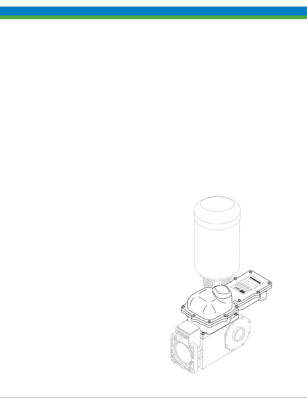
1. INTRODUCTION
The ECA is a microprocessor based stroke length control device for use with the PULSAR diaphragmmetering pump. It has been designed to operate in a variety of industrial environments. This
document describes the ECA controller only. The operation and maintenance of the PULSAR
metering pump is covered in the pump IOM. Please refer to this IOM for important safety and
operational instructions for your PULSAR pump.
1.1 Description
The ECA is an electromechanical servo controller dedicated to the PULSAR diaphragm metering
pump series. The unit is physically attached and integrated into the pump's design. The controller
allows for precise adjustment of output flow of a process media by means of stroke length
positioning.
The ECA is designed for the international industrial market. The analog control signals offer
flexible remote control. They are fully isolated - from each other as well as earth ground - for
improved protection and reliability.
The ECA is designed to simplify and automate the calibration of the analog signals. Analog signal
calibration is accomplished by simple push button entry. Calibration functions must be completed
while the internal circuitry of the unit is accessible, and therefore at a time when the surrounding
environment is non-hazardous.
1.2 Standard Features
NEMA 7 enclosure
4-20mA input and output
EEPROM storage of calibration data.
Diagnostics and Self-Test mode
The ECA is available for 120 or 240 VAC
operation, at either 50 or 60 Hz. Each ECA
controller must be operated on the appropriate
AC supply as per the nameplate ratings.
1
Page 8

2. SAFETY
The ECA is a sophisticated microprocessor based controller for use only with PULSAR diaphragm
metering pumps. It yields tremendous control capacity -- electrical, mechanical and (in conjunction
with the PULSAR pump) hydraulic in nature. In consideration of SAFETY, the user should be
mindful of this relative to his/her safety, that of co-workers and of the process environment. Please
consider the following prior to the installation and operation of an ECA controlled PULSAR metering
pump:
2.1 General Safety
The ECA was designed as a stroke length position actuator for operation solely with the PULSAR
metering pump. Use for any other application is considered un-safe and voids all certification
markings and warranties.
2.2 Explosive Atmosphere Safety
EXPLOSION HAZARD -- DO NOT PERFORM INSTALLATION, CALIBRATION, OR MAINTENANCE OF
ANY KIND ON THIS DEVICE WHILE CIRCUIT IS LIVE AND THE AREA IS KNOWN TO BE HAZARDOUS
R
EMOVAL OF THE ENCLOSURE COVER TO PERFORM SIGNAL CALIBRATIONS MUST BE DONE ONLY
IF THE AREA IS KNOWN TO BE NON-HAZARDOUS. CARE MUST BE TAKEN TO ENSURE PROPER RE-
INSTALLATION OF THE COVER GASKET AND THE COVER BOLTS MUST BE TIGHTENED SECURELY.
.
With the proper marking, this equipment is suitable for use in:
a) Class I, Division 1, Groups C & D
b) Zone 1, Group IIB
c) Non-hazardous locations
2.3 Electrical Safety
The ECA 's electrical installation must conform to all location relevant electrical codes.
INSTALLATION AND ELECTRICAL MAINTENANCE MUST BE PERFORMED BY A QUALIFIED
ELECTRICIAN
.
Before installing or servicing this device, all power must be disconnected from the source at
the main distribution panel. Certain calibration functions must be completed while the electronic
section of the unit is exposed and power is applied to the unit, be certain to ensure that proper
procedures are followed and that fingers, tools, and wiring does not contact exposed circuitry and
components.
The ECA emits electromagnetic energy and generates radio frequency interference. Its use is
restricted to industrial applications. The user bears all responsibility for shielding this
energy/interference.
2.4 Hydraulic Safety
Thoroughly review and adhere to the contents of the PULSAR Installation, Operation, Maintenance
Instruction manual (current version) for hydraulic installation of your PULSAR metering pump.
2
Page 9

3. EQUIPMENT INSPECTION
Check all equipment for completeness against the order and for any evidence of shipping damage.
Shortages or damage must be reported immediately to the carrier and your Pulsafeeder representative.
3.1 Storage Instructions
The ECA can be successfully stored for extended periods. The key to this success is control of
temperature and humidity.
3.1.1 Short Term (0 - 12 months)...
The ECA should be stored in a temperature and humidity controlled environment. It is preferable
to keep the temperature constant in the range of -18 to 60° Celsius (0 to 140° Fahrenheit). The
relative humidity should be 0 to 90% non-condensing.
If the ECA is installed on the pump, it should not be removed during this period - provided the
above conditions can be applied to the pump as well.
If the ECA is removed from the pump eccentric box, it should be stored in the same pump
mounted orientation. After removing the ECA from the eccentric box, seal the opening with a
dust and moisture proof material. If the ECA was shipped in its own carton, it should be stored
in that carton.
3.1.2 Long Term (12 months or more)...
Storage of the ECA for periods of longer than twelve months is not recommended. If extended
storage is unavoidable, the ECA should be stored in accordance with those conditions stipulated
for Short Term Storage. In addition, a porous bag of 85g (3 oz) silica gel or similar desiccant
should be placed within the enclosure. The cover should be re-installed to seal the desiccant
within the enclosure. The two conduit connections must be tightly capped. Inspect the unit
carefully for any signs of damage before placing it into operation.
3
Page 10

4. INSTALLATION
4.1 Location
Review the Safety section prior to installing the ECA. It contains important information required to
properly install and operate the ECA in industrial environments.
The site selected for the installation of your ECA is largely dependent on that of the PULSAR
metering pump. Please review the PULSAR Installation Operation Maintenance Instruction Manual
(current version) provided with your PULSAR metering pump. It details system related issues that
are important to proper operation of the PULSAR metering pump. Be mindful of the following ECA
related issues when selecting a site. Avoid locations where the ECA would be subjected to extreme
cold or heat. Note the warning statement. The installation of this device must comply with national,
state and local codes.
AVOID LOCATIONS WHERE THE ECA WOULD BE SUBJECTED TO EXTREME COLD OR HEAT
[LESS THAN -18° CELSIUS (0° FAHRENHEIT) OR GREATER THAN 40° CELSIUS (104°
FAHRENHEIT)] OR DIRECT SUNLIGHT. FAILURE TO OBSERVE THIS WARNING COULD
DAMAGE THE
ECA AND VOID ITS WARRANTY.
4.2 Installation Notes
1. The ECA is a microprocessor-based controller that uses static sensitive CMOS components. Do
not make any electrical connections (high or low voltage) without adequately grounding the ECA
and the worker to eliminate any electrostatic charge between the two. A conductive wrist strap
worn by the worker and attached to the ECA enclosure is adequate to satisfy this requirement.
2. Conduit connections can carry fluids and vapors into the ECA causing damage and void the
warranty. Care should be taken when installing conduit to protect against fluid/vapor entry. If
necessary, provide sealed entries or conduit drains near the point of entry.
3. All applicable codes and regulations should be adhered to in the installation and wiring of the
ECA, especially if installed in a hazardous environment.
4
Page 11
4.3 Housing Access
All wiring and programming of the ECA must be accomplished through the removal of the
housing cover. Use this procedure for removal and replacement:
THIS PROCEDURE REQUIRES REMOVAL OF THE ENCLOSURE COVER. THIS SHOULD BE
DONE ONLY IF THE AREA IS KNOWN TO BE NON
-HAZARDOUS.
Cover Removal
1. Disconnect power at the source.
2. Loosen and remove the 13 Allen screws holding the cover in place (5mm Allen wrench).
3. Grasp both ends of the cover and lift straight up.
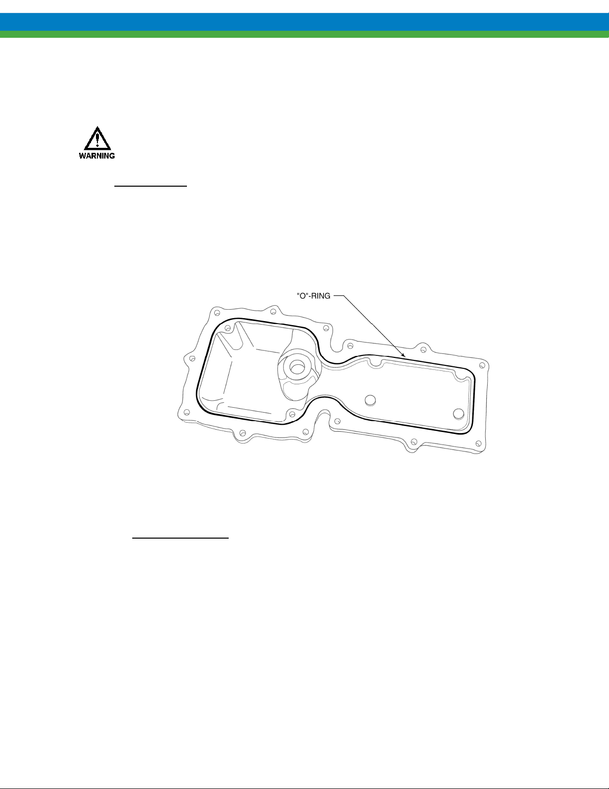
4. Once the cover has been lifted clear of the gear train, rotate the cover 180, and set the cover
aside with the installed “O”-Ring facing up as shown in the illustration below. Be careful to
note the position of the o-ring seal and ensure that it is not misplaced during service.
Figure 1
Cover Reinstallation
1. Inspect the “O”-Ring for any indication of damage. Clean the o-ring carefully.
2. If damage is detected, remove and replace the “O”-Ring.
a. Gently lift the “O”-Ring up and out of the channel.
b. Clean the channel of any remaining residue.
c. Lightly coat the “O”-Ring channel and surrounding mating surfaces with
Super-O-Lube™ or equivalent.
d. Insert the new “O”-Ring in the channel, working the “O”-Ring around the channel
until a proper fit is achieved.
5
Page 12

3. Verify that the mating surface of the lower half of the ECA is clean.
4. Verify the guide pins are in place in the lower half of the ECA housing.
Figure 2
5. Position the housing cover over the lower half and set in place. Do not force the cover as
difficulty in assembly indicates mis-alignment.
6. Insert and hand-tighten the 13 Allen screws at first.
Figure 3
7. Check the cover joint using a 0.0015in (0.038mm) feeler gage. Clearance should be less than
0.0015in (0.038mm) such that the feeler gage will not enter the joint more than 0.125in
(3.2mm) at any point. If necessary, torque the cover bolts to a maximum of 100in-lb (11.3Nm). Use a criss-cross pattern to tighten the bolts to ensure a proper seal around the entire
perimeter.
8. Return the ECA to the desired operating condition.
6
Page 13

)
N
4.4 Electrical Wiring
While the ECA wiring requirements are very simple, always keep in mind that access to these
connectors requires the removal of the cover, and as such this procedure should only be performed
if the area is known to be non-hazardous.
As part of the electrical wiring, a Ferrite core must be used in-line with your connections to meet
EMC emission and immunity standards.
Figure 4
Connections to be made:
1. AC voltage supply. (Each leg is fed separately through part # NP530086-000 once [Line &
Neutral].)
2. Control Cable(s) input (e.g., 4-20mA in, 4-20mA out, and Motor On/Off). (Wire(s) must be
fed through part # NP530087-000 three times.)
FAILURE TO USE THE PROVIDED FERRITE CORES CAN CAUSE EXCESSIVE EMC EMISSIONS
TO BE GENERATED BY THIS DEVICE OR REDUCE ITS IMMUNITY TO EXTERNAL EMISSIONS
WHICH COULD LEAD TO ERRATIC AND POSSIBLY UNSAFE OPERATING CONDITIONS
,
.
Use caution when replacing the cover. If placed improperly, the Ferrite Cores could damage the
motherboard. The example below shows proper core location.
Line
Figure 5
eutral/ Line 2
Control Cable(s
7
Page 14

4.5 AC Supply
THESE PROCEDURES REQUIRES REMOVAL OF THE ENCLOSURE COVER. THIS SHOULD BE
DONE ONLY IF THE AREA IS KNOWN TO BE NON
Connect the proper AC voltage supply to power the ECA at connector J7. Neutral, Earth, and Line
connection points are indicated on the circuit board. For controllers rated at 220VAC, the two line
conductors are wired to the line and neutral inputs. The operating voltage and frequency of the ECA
are factory configured -- an internal motor and capacitor are sized according to voltage and frequency.
If the power supplied to the unit does not match the factory configuration (shown on the nameplate),
the ECA will still operate the internal synchronous motor, eventually causing damage and improper
operation.
To ensure proper operation, the ECA should remain powered at all times. A dry contact input
is provided to provide the ECA with motor status (on vs. off). See Section 4.6.1
High Voltage circuits (e.g., branch) should be run in separate conduit. Do not combine High
Voltage (i.e., greater than 100VAC) lines and Low Voltage (i.e., less than 28VDC) lines in a
common conduit!
-HAZARDOUS.
ref. Section
4.5, AC Supply
ref. Section
4.6.1, Motor
Status Input
Figure 6
8
Page 15
4.6 Control Input and Output Connections
4.6.1 Motor Status Input
The contactor or motor starter controlling the PULSAR motor should be equipped with a normally
open auxiliary contact, which closes to indicate the PULSAR motor is on. This auxiliary contact,
which must be an un-powered, dry contact only, is to be wired to inputs (J4-5 and J4-6) at the
ECA, after removing the factory installed jumper wire. It is critical that the ECA receive this
input, as stroke length should only be adjusted when the pump motor is running. An alternate
contact that represents motor status (for example a relay contact in a local control cabinet) can also
be used for this function.
DAMAGE TO THE ECA MAY OCCUR IF THE STATUS INPUT WIRING RECOMMENDATIONS
ARE NOT FOLLOWED
4.6.2 Analog Current Input
The Analog Input is used for remote control of the pump flow. It accepts current inputs anywhere
in the range of 0 to 25mA (e.g., 4-20mA) provided the “span” (the difference between the high
and low value), is greater than 2mA. Use size AWG 16 to AWG 28 wire for hookup. Attach the
positive lead to J4-1 and the negative lead to J4-2. Position indicators are printed on the circuit
board below the terminal. The ECA will provide approximately 160 ohms of resistance to a
current loop. The Analog Input is isolated from all other inputs, outputs and earth ground.
.
4.6.3 Analog Current Output
The Analog Current Output Channel follows the stroke length position. It can be calibrated to
source current in the 0 to 25 mA range (4-20mA factory default). The output can be calibrated for
reverse acting or split ranging operation. The Current Output can be used to control slave devices
(e.g., ECA 's, ELMA's, PULSAMATICs, etc.) or to fulfill closed loop system requirements. Use
size AWG 16 to AWG 28 wire for hookup. Attach the positive lead to J4-3 and the negative lead
to J4-4. The analog output will drive a maximum load of approximately 700 ohms. The Analog
Output is isolated from all other inputs, outputs, and earth ground.
ref. Section 4.6.3,
Analog Output
ref. Section 4.6.2,
Analog Input
9
Page 16
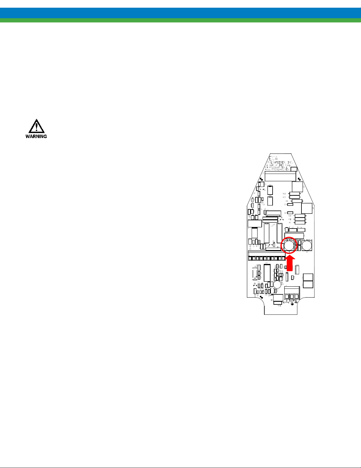
Figure 7
4.7 System Calibration
4.7.1 Analog Input Signal Calibration
The analog input signal should be calibrated to each system. To perform a calibration, the signalgenerating device (e.g., PLC) must be powered up, wired to the ECA and capable of altering its
output from the minimum to the maximum signal. Note that the minimum span, or difference
between low and high values, is 2.0 mA. The ECA will not actuate to change stroke length during
this process.
THIS PROCEDURE REQUIRES REMOVAL OF THE ENCLOSURE COVER. THIS PROCEDURE
SHOULD BE PERFORMED ONLY IF THE AREA IS KNOWN TO BE NON
1. With the cover removed and power supplied to the ECA, press and
release the white Input Cal pushbutton. The Cal Input LED will blink
slowly, indicating the ECA is ready to accept the low (0% stroke)
analog input value.
2. Send the low analog signal to the ECA (generally 4 mA) from the
signal-generating device (e.g., PLC). It is highly recommended that
you use the actual signal the ECA will be receiving during calibration.
3. When the low analog input value has stabilized (allow 10-15 seconds),
press the white Input Cal pushbutton to accept it as the 0% flow
analog signal value. The Cal Input LED will now blink rapidly.
4. Send the desired analog high signal (generally 20 mA).
5. When the high analog input value has stabilized (allow 10-15
seconds), press the white Input Cal pushbutton to accept it as the high
(100% stroke) analog signal value. The Cal Input LED will
extinguish, unless the minimum span of 2.0 mA is violated, then the
ECA will return to step 1 above.
Reverse-acting calibration is accomplished by input of a high signal
(i.e., 20 mA) as the low (0% stroke) analog input value, and a low
signal (i.e. 4 mA) as the high (100% stroke) analog signal.
6. Replace the cover (see Section 4.3) and continue with the output
calibration if that function is being utilized.
-HAZARDOUS.
Figure 8
4.7.2 Analog Input Signal Loss
A failure of the analog input signal is detected if the input signal falls below the calibrated 0%
stroke signal by 0.3 mA. For example, if the ECA is calibrated with a range of 4-20 mA and the
signal falls to 3.6 mA then a failure will be logged. If the calibrated 0% stroke signal is 0.3 mA or
less, no signal loss failure will be generated. Input signals above the calibrated 100% stroke signal
are simply ignored, the stroke position will be driven to 100% and no error condition occurs.
In the event of a loss of analog signal or an abnormally low signal, the ECA will drive to the zero
stroke position. The ECA will recover once a valid analog signal is present and resume control to
the appropriate setpoint.
Jumper J6 should be left in the factory default position. Do not change the position of this jumper.
10
Page 17
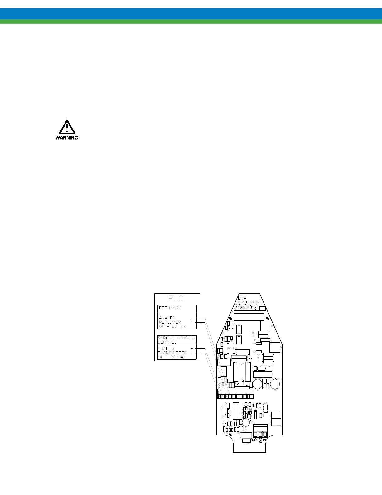
4.7.3 Analog Output Signal Calibration
THIS PROCEDURE REQUIRES REMOVAL OF THE ENCLOSURE COVER. THIS SHOULD BE
DONE ONLY IF THE AREA IS KNOWN TO BE NON
To calibrate the analog output, you need to attach
an ammeter to the output circuit, or have the ECA
wired to the PLC or other device. It is
recommended that you calibrate to the actual
remote equipment and set the analog output values
at whatever is required by that equipment. For
example, the ECA output can be adjusted at the
zero point so that the screen on the PLC system
reads zero %, regardless of the actual mA value of
the signal. The ECA will not actuate to change
stroke length during this process.
-HAZARDOUS.
Figure 9
1. With the cover removed and power supplied to the ECA, press the
black Output Cal pushbutton. The Cal Output LED will blink
slowly and current output will be set to the present analog out low
calibration value. (4 mA factory default)
2. Press and hold the white Input Cal pushbutton to increase current
output until the desired low setpoint is reached. Release and press
again to decrease current output. Current will change in steps of
approximately 0.02 mA, at a rate of 20 steps per second.
3. Press the black Output Cal pushbutton. The Cal Output LED will
blink rapidly and current output will be set to the present analog
out high calibration value. (20 mA factory default)
4. Press and hold the white Input Cal pushbutton to decrease current
output until desired high setpoint is reached. Release and press
again to increase current output. Current will change in steps of
0.125 mA at a rate of 20 steps per second.
5. Press the black Output Cal pushbutton. The Cal Output LED will
extinguish, unless the minimum span of 2.0 mA is violated, then
the ECA will return to step 1 above.
6. Replace the cover (see Section 4.3) and return power to the ECA.
Figure 10
11
Page 18

4.8 Mechanical Zero Calibration
THIS PROCEDURE REQUIRES REMOVAL OF THE ENCLOSURE COVER. THIS SHOULD BE
DONE ONLY IF THE AREA IS KNOWN TO BE NON
If the ECA was shipped with a pump attached, the mechanical zero calibration was performed at the
factory. Typically this setting will not change during the shipping procedure, but performing a
mechanical zero calibration will assure accurate operation of your controller. If the ECA was
shipped without a pump attached, performing the mechanical zero calibration is mandatory to
successful installation/operation. If the ECA controller does not have a valid zero calibration at
power up, a calibration will automatically be performed. The pump should be running during this
process to ensure an accurate zero position is calibrated. Ensure it is safe to operate the pump during
the procedure.
1. Verify that power to the ECA is off
2. Remove the enclosure cover.
3. Press and hold the BLACK pushbutton
4. Apply power to the ECA. (Plug in the power cord or energize power at the main panel.)
5. A mechanical zero calibration routine will begin. Once the ECA begins the routine you may
release the pushbutton.
6. Allow the calibration routine to complete.
7. Replace the cover (see Section 4.3) and return power to the ECA.
-HAZARDOUS.
4.9 Factory Re-initialization
THIS PROCEDURE REQUIRES REMOVAL OF THE ENCLOSURE COVER. THIS SHOULD BE
DONE ONLY IF THE AREA IS KNOWN TO BE NON
A Factory Re-initialization restores all EEPROM calibration settings and mode settings to their
factory default values and is typically not required. The user also needs to keep in mind that once the
Factory Re-Initialization is preformed, all user calibrations are erased. This procedure should be
performed only if the user has reason to believe that the internal ECA memory has become corrupted.
A number of factors could cause this including:
1. Disregard of electrostatic precautions during installation,
2. Improper wiring,
3. Voltage surges, spikes, etc.
The condition usually manifests itself with inconsistent or erratic operation. The pump should be
running during this process to ensure an accurate zero position is calibrated. Ensure it is safe to
operate the pump during the procedure.
1. Verify that power to the ECA is off.
2. Remove the enclosure cover.
3. Press and hold both black and white pushbuttons while applying power to the ECA. (Plug
in the power cord or energize power at the main panel.)
4. Release the CAL pushbuttons and the unit is restored to the factory default settings.
5. The unit will automatically perform a new mechanical zero calibration (see Section 4.8)
as part of the Factory Re-Initialization routine.
6. Perform any additional calibration procedures as required.
7. Replace the cover (see Section 4.3) and return power to the ECA.
-HAZARDOUS.
12
Page 19

5. DIAGNOSTICS
5.1 Trouble Code Reporting
The ECA is designed to be as fault tolerant and self-recovering as possible. However, should certain
conditions occur which make proper operation impossible, it is important to be able to diagnose the
cause of the problem.
When the ECA encounters an abnormal condition, a trouble code is indicated using the CAL LED’s
as follows:
1. Both LED’s will blink once.
2. The Cal Input LED will blink some number of times to signal the first trouble code digit.
3. The Cal Output LED will blink some number of times to signal the second trouble code
digit.
This sequence will repeat until the trouble condition is cleared.
5.2 Trouble Codes
Code Description Definition
The CPU failed to read an encoder pulse, or has not received the expected
11
or
12
Encoder Error
signals in a certain amount of time. Thus, the controller has lost its zero
reference. It then attempts to recover by doing a mechanical zero
calibration. If the mechanical zero calibration is successful, this error is
cleared, and normal operation continues. If further errors prevent successful
mechanical zero calibration, this error is a fatal error and requires user
intervention. Cleared by cycling power.
Failure to reach commanded position within the timeout period (5 minutes).
After 10 minutes, the error will clear and the controller will automatically
13
14
21
22
23
24
33
Position Error
Over Temperature
Signal Loss
Self-Test Signal
Error
Self-Test Signal
Error
Self-Test
Thermistor Error
Self-test passed Refer to Self-Test Mode description for additional information.
retry the position adjustment. If the error continues to occur for ten
consecutive times, no further retries will be attempted, and the error will
become a fatal error requiring user intervention. The error can be cleared by
cycling power.
The motor thermistor indicates the motor case temperature has reached
approximately 90C (194F). This will stop motor operation until the motor
case temperature drops below approximately 80C (176F), when it will
clear automatically. This insures that motor duty cycle is not excessive in
high ambient temperature situations.
The Analog input signal dropped more than 0.3 mA below the low cal point.
This error clears automatically when the analog input signal returns to
normal.
The Analog output signal and analog input signal at 0% stroke position do
not agree (refer to Self-Test Mode description for further details).
The Analog output signal and analog input signal at 100% stroke position do
not agree (refer to Self-Test Mode description for further details).
Thermistor readings are not within specifications. Contact factory for
assistance.
13
Page 20

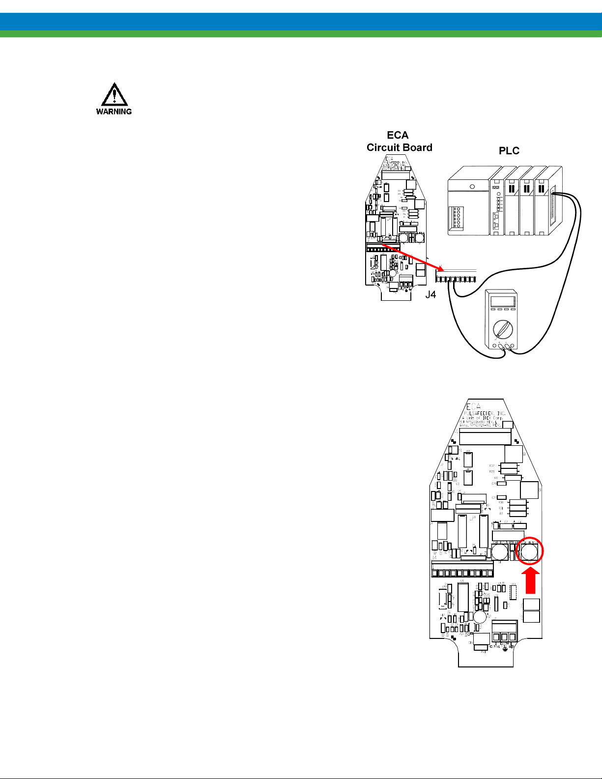
5.3 Self Test Mode
The ECA has a diagnostic test mode which can be used to verify performance and troubleshoot
problems. To initiate the self-test:
1. Remove power from the ECA, and remove the top cover.
2. Disconnect any field wires attached to J4, and connect Analog Out to Analog In. (jumper J4-1 to
J4-3 and J4-2 to J4-4).
Figure 11
3. Press and hold the WHITE button.
4. Apply power to the ECA. The ECA will enter the self-test mode and perform the following tests:
1. Calibrates mechanical zero position, if necessary.
d) Drives to the 0% stroke position, testing the motor drive and the encoder. Both LED’s
will blink if the zero calibration fails.
e) Pauses for 30 seconds, then confirms that the analog output and the analog input are
correct. Sets trouble code 22 if analog ports do not agree.
f) Drives to the 100% stroke position, testing the motor drive and the encoder. Sets the
trouble code to 13 if the 100% position is not attainable.
g) Pauses for 30 seconds, then confirms that the analog output and the analog input are
correct. Sets trouble code 23 if analog ports do not agree.
h) Confirms that the motor thermistor is reading in correct range. Sets trouble code 24 if
thermistor readings are outside specifications.
i) Sets trouble code 33 to indicate test passed.
5. Turn power off to the ECA, and remove the jumpers installed in step 2. Re-connect field wires.
6. Replace the cover (see Section 4.3) and return power to the ECA.
5.4 Error Recovery
In cases of abnormal operation, the following procedure is recommended:
1. First, check all power and process connections to ensure all wiring is secure and properly
connected.
2. Check the internal connections within the ECA, ensure that the molded plugs from the stroke
adjustment motor and encoder are secure.
3. Perform a Factory Re-initialization, as described in Section 4.9. This will also force a new
mechanical zero calibration to be performed. The pump motor should be operating during this
process as the ECA will adjust stroke to re-locate the zero position. Ensure that it is safe to
operate the pump during this step.
4. Perform a new analog input signal calibration as per Section 4.7.1.
5. Perform a new analog output signal calibration as per Section 4.7.3.
14
Page 21

6. Specifications
Input Power
Stroke Length Control
Stroke Adjustment response
Analog Input
Operating Range
Input Impedance
Minimum Span
Isolation
Conditioning
Analog Output
Operating Range
Maximum Load
Minimum Span
Conditioning
Isolation
Status Input
Motor On/Off
Environmental
Rated Ambient Temperature
Storage Ambient Temperature
Enclosure
Approvals
115 Volt/ 60Hz, 115 Volt/ 50Hz, 220 Volt/ 60 Hz, or 220 Volt/
50Hz
0 – 100% control range
Resolution – 0.0625% increments
Approximately 1% per second
0 to 25.5mA (4-20 mA factory default)
160 ohms
2.0 mA
500V from all other inputs, outputs and ground, optically
isolated
8 second running average.
Split Ranging and Reverse Acting accessible via calibration.
0 to 25.5mA (4-20 mA factory default)
700 ohms
2.0 mA
None. Output represents current stroke position.
Split Ranging and Reverse Acting accessible via calibration.
500V from all other inputs, outputs and ground, optically
isolated.
Optically isolated dry contact input. Open contact indicates
motor is off. Controller will then suspend all stroke control
action. Motor starter should provide a contact for connection
here.
-20C to 40C (-4F to 104F)
-25C to 60C (-13F to 140F)
NEMA7, IP66, NEMA4X
UL/ULC - NEMA 7
UL 1203: Class I, Division I, Groups C & D Hazardous
Locations
Cenelec–IP66
Cenelec – XP, Class I, Zone I, Group IIB, (EEx d IIb T6)
(DEMKO)
CE – LVD, EMC
15
Page 22

7. Power-Up Options Summary
Upon application of input power, the ECA will perform certain functions if the pushbuttons are used, as
follows:
Pushbuttons pressed
at power-up
Function Reference
Section
NONE Normal operation, use all calibration data from memory
BLACK key Forces a mechanical zero position calibration
WHITE key Initiates self-test (with jumpers as per Section 5.3)
BOTH keys (WHITE
and BLACK)
Resets all to factory default values, performs an automatic
mechanical zero calibration, analog signals will require recalibration
8. Field Wiring Summary
Connector Location
Line Line connection 115VAC, Line 1 connection 230 VAC
J7
Neutral Neutral connection 115 VAC, Line 2 connection 230 VAC
Ground Earth ground connection 115 or 230 VAC
Function/Connection Reference
4.8
5.3
4.9
Section
4.5
4.5
4.5
Position 1 Analog input (control) signal positive (+)
Position 2 Analog input (control) signal common (-)
J4
Position 3 Analog output (feedback) signal positive (+)
Position 4 Analog output (feedback) signal common (-)
Position 5 Motor enable dry contact
Position 6 Motor enable dry contact
16
4.6.2
4.6.2
4.6.3
4.6.3
4.6.1
4.6.1
Page 23

Bulletin #: IOM-ECA-0800-Rev G
(for s/n 611000-x and higher)
 Loading...