

Page 1

INSTALLATION
OPERATION
MAINTENANCE
INSTRUCTION
BULLETIN No. IOM-PS-DLCM-1101-Rev E
Manufacturer’s of Quality Pumps,
Controls and Systems
Engineered Pump Operations
2883 Brighton-Henrietta Townline Road
Rochester, New York 14623
Telephone: (585) 292-8000 Fax: (585) 424-5619
http://www.pulsa.com
E-mail: pulsa@pulsa.com
Page 2

DLCM™ FACTORY SERVICE POLICY
Your DLCM is a state of the art microprocessor based stroke length and motor speed control for use with
PULSAR Diaphragm Metering Pumps. It includes extensive on-board diagnostics. If you are experiencing
a problem with your DLCM, first review the diagnostic menu, then consult the trouble shooting guide. If
the problem is not covered or cannot be solved, please contact your local PULSA Series Sales Organization
or our Technical Service Department at (585) 292-8000 for further assistance. Do not open or tamper
with your DLCM enclosure as this will void the warranty.
Trained individuals are available to diagnose your problem and arrange a solution. Solutions may include
purchasing a replacement unit or returning the DLCM to the factory for inspection and repair. All returns
require a Return Material Authorization (R.M.A.) number to be issued by Pulsafeeder. Replacements
purchased under a possible warranty situation may be credited after an examination of the original DLCM
by Pulsafeeder personnel.
Certain components may be purchased for replacement. Refer to Section 15 – Spare Parts for more
information and part numbers. Parts purchased to correct a warranty issue may be credited after
examination of the original parts by Pulsafeeder personnel. Parts returned for warranty consideration that
test satisfactorily, will be sent back to the originator freight collect.
Any field modifications will void the Pulsafeeder DLCM warranty. Out-of-warranty repairs will be
subject to Pulsafeeder's standard bench fees and testing costs associated with replacement
components.
DLCM LIMITED WARRANTY
The manufacturer warrants the DLCM, microprocessor-based controller against defects in materials or
workmanship for a period of one year under normal use from date of shipment. The manufacturer's
liability is limited to the repair or replacement of any failed component which is proven defective in
material or workmanship upon manufacturer's examination. This warranty does not include removal or
installation costs and in no event shall the manufacturer's liability exceed the selling price of such
equipment.
This warranty does not extend to damage by corrosion, erosion, mishandling, any force of nature or any
other conditions beyond the seller's reasonable control.
The manufacturer disclaims all liability for damage to its products through improper installation,
maintenance, use or attempts to operate such products beyond their functional capacity, intentionally or
otherwise or any unauthorized repair. The manufacturer is not responsible for consequential or other
damages, injuries or expenses incurred through the use of its products.
The above warranty is in lieu of any other guarantee, either expressed or implied. The manufacturer makes
no warranty of fitness or merchantability. No agent of ours is authorized to make any warranty other than
the above.
FCC Warning
This equipment generates and uses radio frequency energy. If not installed and used properly, in strict
accordance with the manufacturer’s instructions, it may cause interference to radio communications.
Operation of this equipment in a residential area is likely to cause interference in which case the user, at his
own expense, will be required to take whatever measures necessary to correct the interference.
Copyright
Copyright © 2001 Pulsafeeder, Inc. All rights reserved.
Information in this document is subject to change without notice. No part of this publication may be
reproduced, stored in a retrieval system or transmitted in any form or any means electronic or mechanical,
including photocopying and recording for any purpose other than the purchaser’s personal use without the
written permission of Pulsafeeder.
ii
Page 3

Table of Contents
1. I
NTRODUCTION
.....................................................................................................................................1
1.1 Description...............................................................................................................................1
1.2 DLCM Standard Features .......................................................................................................2
1.3 Options.....................................................................................................................................2
1.4 Accessories .............................................................................................................................2
2. S
AFETY CONSIDERATIONS
....................................................................................................................3
2.1 General Safety .........................................................................................................................3
2.1.1 Explosive Atmosphere Safety ........................................................................................ 3
2.1.2 Electrical Safety ...............................................................................................................3
2.1.3 Mechanical Safety............................................................................................................3
2.1.4 Hydraulic Safety...............................................................................................................3
3. E
QUIPMENT INSPECTION
4. S
TORAGE INSTRUCTIONS
.......................................................................................................................4
......................................................................................................................4
4.1 Storage Length ........................................................................................................................4
4.1.1 Short Term (0 - 12 months).............................................................................................4
4.1.2 Long Term (12 months or more) ....................................................................................4
5. I
NSTALLATION
......................................................................................................................................5
5.1 Location ...................................................................................................................................5
5.2 Installation Notes ....................................................................................................................6
5.3 Electrical Wiring ......................................................................................................................6
5.3.1 Getting Started.................................................................................................................7
5.3.2 Finding your way around the Field Wiring Board ........................................................8
5.4 High Voltage Connections .....................................................................................................9
5.4.1 Supply Power ...................................................................................................................9
5.4.2 PULSAR Motor .................................................................................................................11
5.4.3 Alarm Relay ......................................................................................................................12
5.5 Low Voltage Input Connections ............................................................................................12
5.5.1 Analog Inputs...................................................................................................................13
5.5.2 Alarm Input.......................................................................................................................14
5.5.3 Level Input (Remote Start/Stop).....................................................................................14
5.6 Low Voltage Output Connections .........................................................................................15
5.6.1 Current Output ................................................................................................................. 16
5.6.2 Alarm Dry Contact Output ..............................................................................................16
5.6.3 Run Status or Stroke Counter ........................................................................................ 17
5.7 Tachometer Input ....................................................................................................................17
5.8 Motor Thermostat....................................................................................................................19
5.9 Serial Communications Input ................................................................................................19
5.10 Fuse Replacement...................................................................................................................21
6. S
TART UP INSTRUCTIONS
......................................................................................................................22
6.1 Overview ..................................................................................................................................22
6.1.1 User Interface Familiarization. .......................................................................................22
6.1.2 Check Wiring and Close Access cover .........................................................................24
6.1.3 Confirm Correct Incoming Power ..................................................................................25
6.1.4 Confirm Display and Keypad functionality ................................................................... 25
6.1.5 Performing a Factory Re-initialization...........................................................................26
6.1.6 Test Pump Motor .............................................................................................................27
6.1.7 Set Time and Date............................................................................................................28
6.1.8 Flow Calibration (1-point). ..............................................................................................29
6.1.9 Analog Input Calibration.................................................................................................30
6.2 Wrapping up. ...........................................................................................................................31
7. G
ENERAL OPERATION
..........................................................................................................................32
7.1 General Operation Instructions .............................................................................................32
7.1.1 Pump Flow Calibration....................................................................................................32
7.1.2 Analog Input Signal Calibration ..................................................................................... 36
7.1.3 Reverse Acting Analog Input Signal Calibration.......................................................... 39
7.1.4 Analog Output Signal Calibration .................................................................................. 40
iii
Page 4

7.2 Menu .........................................................................................................................................41
7.2.1 Alarm, and Error messages............................................................................................42
7.2.2 Diagnostics ......................................................................................................................43
7.2.3 Set Time and Date............................................................................................................45
7.2.4 Analog Signal Failure Set Up .........................................................................................47
7.2.5 MODBUS Signal Failure Setup ....................................................................................... 50
7.2.6 Analog Output Set Up .....................................................................................................53
7.2.7 Motor Speed Display .......................................................................................................54
7.2.8 End Point Set Up..............................................................................................................55
7.2.9 Leak Detection Failure Set Up........................................................................................58
7.2.10 Level / Remote / Start – Stop Set Up..............................................................................59
7.2.11 Digital Output Set Up.......................................................................................................62
7.2.12 Motor Thermostat Set Up................................................................................................ 64
7.2.13 Over Temperature Set Up ...............................................................................................65
7.2.14 Power Failure Set Up.......................................................................................................66
7.2.15 Alarm Relay ......................................................................................................................67
7.2.16 Analog Mode ....................................................................................................................67
7.2.17 MODBUS Mode ................................................................................................................69
7.2.18 Security............................................................................................................................. 72
7.2.19 Number Format ................................................................................................................73
7.2.20 Contrast Adjust................................................................................................................74
7.2.21 Serial Communications...................................................................................................74
7.2.22 Serial Diagnostics............................................................................................................77
7.2.23 Language..........................................................................................................................79
7.2.24 Factory Default Settings .................................................................................................79
7.3 Units..........................................................................................................................................80
7.4 Varying the Flow Rate - Manually ..........................................................................................81
7.5 Mode .........................................................................................................................................81
7.6 Batch.........................................................................................................................................81
7.6.1 One Time Only .................................................................................................................81
7.6.2 Repeating .........................................................................................................................82
7.6.3 Overlapped .......................................................................................................................82
8. D
IAGRAMS
9. S
PECIFICATIONS
: I
NSTALLATION
/ C
OMPONENT
..............................................................................................86
...................................................................................................................................88
9.1 Overview ..................................................................................................................................88
10. F
ACTORY DEFAULT VALUES
11. T
ROUBLE SHOOTING GUIDE
.................................................................................................................91
..................................................................................................................94
11.1 System Diagnostics ................................................................................................................ 94
11.1.1 Encoder Diagnostics.......................................................................................................101
11.1.2 Tachometer Troubleshooting.........................................................................................102
11.1.3 Tachometer Upgrade Adjustment Instructions ............................................................ 103
12. C
ONVERSION (MANUAL TO
13. G
ENERAL REPAIRS
...............................................................................................................................106
DLCM) .......................................................................................................104
13.1 Emergency Manual Pulsar Operation ...................................................................................106
13.2 DLCM Replacement.................................................................................................................107
14. P
ULSANET SPECIFICATION
...................................................................................................................114
14.1 Introduction .............................................................................................................................114
14.2 Operational Overview .............................................................................................................114
14.3 MODBUS Messaging...............................................................................................................115
14.4 PulsaNet DDE Server Messaging ..........................................................................................115
14.5 Coils..........................................................................................................................................116
14.6 Input Bits (1x references) ....................................................................................................... 116
14.7 Input Registers ........................................................................................................................117
14.8 Holding Registers....................................................................................................................117
15. MODBUS M
.................................................................................................................................123
ODE
15.1 Introduction .............................................................................................................................123
15.2 General Discussion.................................................................................................................123
16. S
PARE PARTS
......................................................................................................................................124
iv
Page 5

D
IAGNOSTIC FORM
......................................................................................................................................125
v
Page 6

Conventions
For the remainder of this bulletin, the following Conventions are in effect.
A
WARNING DEFINES A CONDITION THAT COULD CAUSE DAMAGE TO BOTH
. P
THE EQUIPMENT AND THE PERSONNEL OPERATING IT
ATTENTION TO ANY WARNING
Notes are general information meant to make operating the equipment easier.
Tips have been included within this bulletin to help the operator run the
equipment in the most efficient manner possible. These “Tips” are drawn
from the knowledge and experience of our staff engineers, and input from the
field.
This is a procedure heading. A Procedure Heading indicates the starting
point for a procedure within a specific section of this manual.
.
AY CLOSE
vi
Page 7

1. Introduction
The DLCM is an advanced microprocessor based controller designed for use with the PULSAR diaphragm
metering pump. It controls the output of the pump by varying its stroke rate and the amount of fluid
discharged with each stroke. It has many advanced features that allow it to operate in a wide variety of
industrial environments.
This instruction manual covers all standard features of the DLCM and where applicable, specific options.
1.1 Description
The DLCM integrates a motor speed controller and a stroke length controller into a single pump mounted
package. Its purpose is to precisely adjust the flow of a process media by adjusting the pump motor speed
and stroke length.
The DLCM is designed for the international industrial market. The device is factory configured and
calibrated for the attached pump. The man/machine interface is user friendly. Local setup and control is
achieved through the nine button keypad and a back-lit two-line liquid crystal display. Pump output is
displayed as a percentage of stroke length position and motor speed, or in units of calibrated flow: CMH,
GPH, LPH, CCH, CMM, GPM, LPM, or CCM. In addition, the DLCM display supports any one of four
languages: English, French, German or Spanish.
The DLCM supports a variety of remote control options. These inputs and outputs are fully isolated for
improved protection and reliability. A Batch feature, with up to three independent programs, supplements
the control features and allows for greater flow turn down.
The DLCM includes the PULSAnet Serial Communications system. This allows the DLCM to interface
digitally to other DLC’s, DLCM’s, PLC’s, or PC’s using the MODBUS™ communications protocol over
a 4 wire RS-485 network.
The DLCM is designed to simplify and automate the calibration of pump flow and analog signals. Flow
calibration uses on-screen prompting, automated pump operation, and automatic curve fitting to eliminate
the need for stop-watches, calculators and reduces the possibility of human error. Analog signal
calibration is also accomplished by simple key-pad entry. It includes real-time display of signal levels.
This eliminates the need for external meters.
The DLCM readily accepts PULSAlarm leak detection, Level Input detection or Remote Start/Stop
station inputs that can be configured to stop the pump and/or activate an alarm relay.
The Remote Start/Stop cannot be configured to activate the alarm relay.
Failures are time and date stamped into memory for later retrieval. Other diagnostics include analog
signal failure and line power failure monitoring. These are also time and date stamped and may be preset
to control stroke position or motor status upon detection of a failure.
Security password protection may be activated to prevent tampering. All settings and diagnostics have a
battery back-up for up to 10 years in the absence of power.
The DLCM is available in any combination of 120/240 VAC, 50/60Hz. Protection exists to prevent
damage against over or under voltage conditions in the event the wrong power line source is used.
1
Page 8

1.2 DLCM Standard Features
DC Motor Speed Control with tachometer feedback
i
Manual Stroke Length Control
i
Keypad
i
Back-lit 2 line 16 character LCD display
i
NEMA 4X Enclosure
i
Two 4-20mA inputs for independent speed and stroke length control
i
One 4-20mA output
i
MODBUS RS-485 Serial Communications
i
10-Year Battery Backed Clock
i
Solid State Alarm Relay
i
Level Input/Remote Start-Stop Inputs
i
PULSAlarm Leak Detection Interface
i
Diagnostics
i
1.3 Options
Operating Voltage/Frequency
i
1.4 Accessories
Pulsanet MODBUS DDE Server
i
2
Page 9

2. Safety Considerations
The DLCM is a sophisticated microprocessor based controller for use only with PULSAR diaphragm
metering pumps. It yields tremendous control capacity – electrical, mechanical and (in conjunction with
the PULSAR pump) hydraulic in nature. In consideration of SAFETY, you should be mindful of this
relative to your safety, that of co-workers and of the process environment. Consider the following prior to
the installation and operation of a DLCM controlled PULSAR metering pump.
2.1 General Safety
The DLCM was designed as a motor speed controller and stroke length position actuator for operation
solely with the PULSAR metering pump. Use for any other application is considered un-safe and voids
all certification markings and warranties.
2.1.1 Explosive Atmosphere Safety
Explosion Hazard -- Do not perform installation or maintenance of any kind on this device while
circuit is live and/or the area is known to be hazardous.
With the proper marking, this equipment is suitable for use in Class I, Division 2, Groups C & D; Zone
2, Groups IIA and IIB or non-hazardous locations only.
2.1.2 Electrical Safety
The DLCM can be considered an industrial stroke length controller with an integrated motor speed
controller. Improper application and use can be hazardous. You are solely responsible for its use.
The DLCM's electrical installation must conform to all relevant electrical codes. Installation and
electrical maintenance must be performed by a qualified electrician. Before installing or servicing this
device, all power must be disconnected from the source at the main distribution panel.
The DLCM emits electro-magnetic energy and generates radio frequency interference. Its use is
restricted to industrial applications. You are responsible for shielding this energy/interference.
2.1.3 Mechanical Safety
When properly installed, the device has only one externally accessible moving part – the hand
adjustment knob. This component is under computer control and as such may actuate without warning.
Care should be taken to keep loose clothing away from this component. Hands and fingers should be
kept clear while the knob is turning under DLCM control.
The DLCM was designed to be service free. It contains no user-maintainable components. Removal of
the entire DLCM as an assembly from the pump is permissible. Do not disassemble the DLCM
enclosure unless instructed to do so in Section 12 of this manual. Evidence of disassembly shall void
the warranty.
2.1.4 Hydraulic Safety
Thoroughly review and adhere to the contents of the PULSAR Installation, Operation, Maintenance
and Instruction manual (Bulletin No. PMP-IOM-96) for hydraulic installation of your PULSAR
metering pump. As a microprocessor controlled device, the DLCM may activate the pump motor
without warning – generating hydraulic pressure and fluid flow. Care should be taken to protect both
users and systems should the pump activate.
3
Page 10

3. Equipment Inspection
When you receive your order, check all equipment for:
Completeness against the shipping document / purchase order
i
For any evidence of shipping damage.
i
Shortages or damage should be reported immediately to the carrier and your PULSAFEEDER
representative.
4. Storage Instructions
The DLCM can be successfully stored for extended periods. The key to this success is temperature and
humidity control.
4.1 Storage Length
4.1.1 Short Term (0 - 12 months)
The DLCM should be stored in a temperature and humidity controlled environment. It is preferable to
keep the temperature constant in the range of -18 to 60° Celsius (0 to 140° Fahrenheit). The relative
humidity should be 0 to 90% non-condensing.
The adjustment knob should be rotated in alternate directions by hand one full revolution every six
months.
If the DLCM is installed on the pump, it should not be removed during this period – provided the above
conditions can be applied to the pump as well. If the DLCM is removed from the pump, it should be
stored in the same pump mounted orientation. After removal of the DLCM from the PULSAR
metering pump, seal the eccentric box opening with a dust and moisture proof material. If the DLCM
was shipped in its own carton, it should be stored in that carton.
4.1.2 Long Term (12 months or more)
Storage of the DLCM for periods of longer than twelve months is not recommended. If extended
storage is unavoidable the DLCM should be stored in accordance with those conditions stipulated for
Short Term Storage. In addition, a porous bag of 85g (3 oz) silica gel or similar desiccant should be
placed beneath the wiring access cover. The cover should be re-installed to seal the desiccant within
the enclosure. The three conduit connections must be tightly capped.
4
Page 11
5. Installation
5.1 Location
Review the Safety section prior to installing the DLCM. It contains information required to properly
install and operate the DLCM in an industrial environment.
The site selected for the installation of your DLCM is largely dependent on that of the PULSAR metering
pump. Review the PULSAR Installation Operation Maintenance Instruction Manual (Bulletin No. PMPIOM-96) provided with your PULSAR metering pump. It details system related issues that are important
to proper operation of the PULSAR metering pump. Consider the following DLCM related issues when
selecting a site. The DLCM should be mounted in an area where the operator has access to the front of
the unit and a clear view of the display panel and keyboard. Avoid locations where the DLCM would be
subjected to extreme cold or heat. Note the warning statement on the next page. The installation of this
device must comply with national, state and local codes.
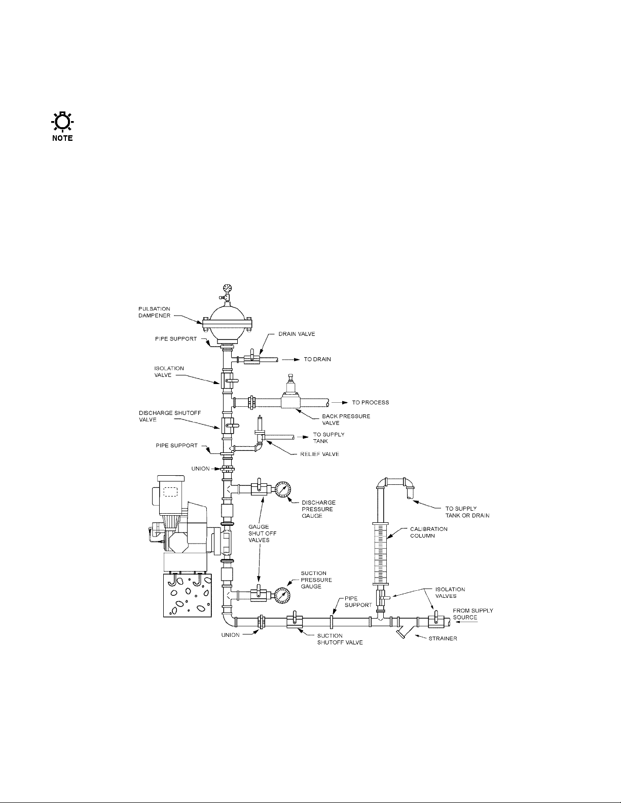
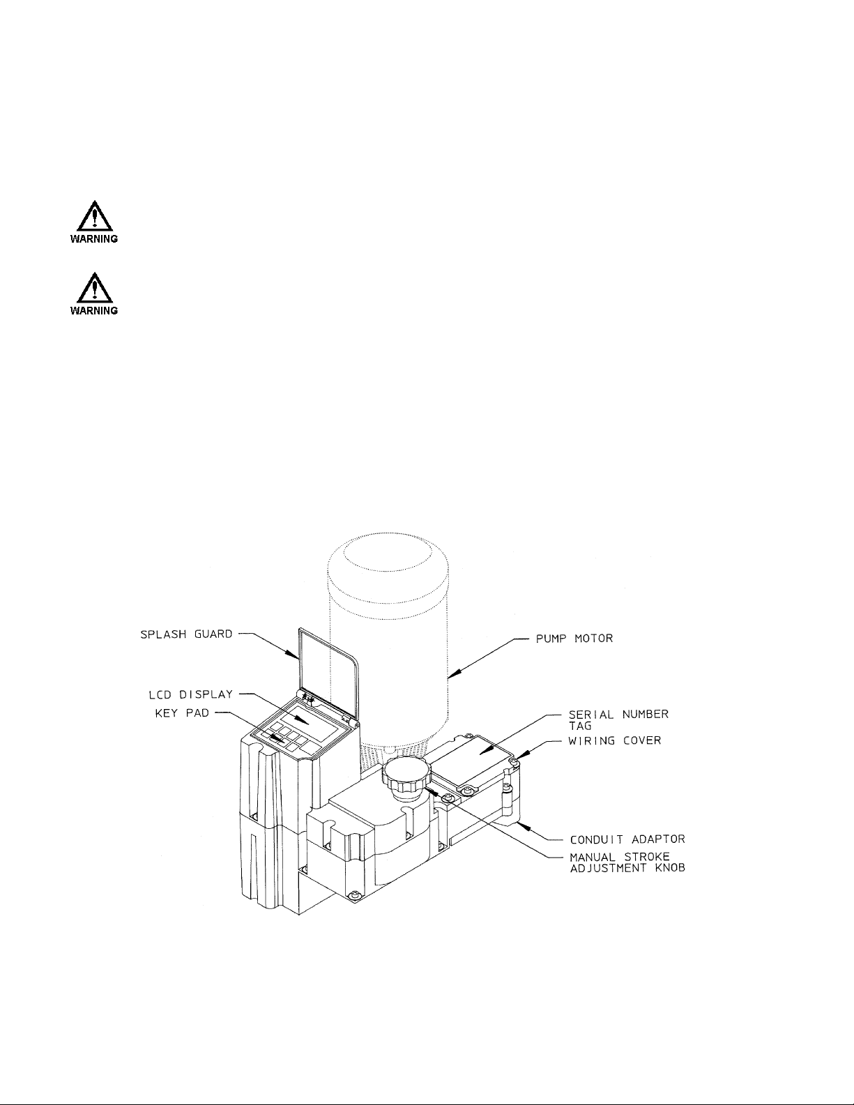
Figure 1 – Typical Installation.
5
Page 12

A
VOID LOCATIONS WHERE THE
[
LESS THAN
F
AHRENHEIT
DLCM
THE
–18
CELSIUS
°
)]
OR DIRECT SUNLIGHT
AND VOID ITS WARRANTY
5.2 Installation Notes
1. The DLCM is a microprocessor based controller that uses electro-static sensitive CMOS components.
Do not make any electrical connections (high or low voltage) without adequately grounding the DLCM
and the worker to eliminate an electro-static charge between the two. A conductive wrist strap worn by
the worker and attached to the DLCM enclosure is adequate to satisfy this requirement.
2. Calibration is an important element of successful DLCM operation. Permanent installation of a
calibration column as depicted in Figure 1 is strongly recommended.
3. Conduit connections can carry fluids and vapors into the DLCM causing damage and void the
warranty. Care should be taken when installing conduit to protect against fluid/vapor entry. If
necessary, provide sealed entries or conduit drains near the point of entry.
5.3 Electrical Wiring
The DLCM has many advanced features that may make wiring the unit appear complicated. Wiring is
actually very simple – one high voltage connection is all that is required to take advantage of a majority
of the DLCM's features. It is highly recommended that you take a step-by-step approach to wiring and
confirming proper DLCM operation:
DLCM
(0
FAHRENHEIT) OR GREATER THAN
°
WOULD BE SUBJECTED TO EXTREME COLD OR HEAT
. F
AILURE TO OBSERVE THIS WARNING COULD DAMAGE
.
40
°
CELSIUS
(104
°
1. Make the high voltage connection. These will allow you to operate the DLCM and attached PULSAR
pump.
2. Power-up and test the DLCM to confirm the connections and check for proper operation.
3. Power-down the DLCM.
4. Decide which low voltage Inputs (e.g., 4-20mA in) will be used and make those connections.
5. Power-up and test the DLCM to confirm the connections and check for proper operation.
6. Power-down the DLCM.
7. Decide which low voltage Outputs (e.g., 4-20mA out) will be used and make those connections.
8. Conduct a final power-up and test the DLCM to confirm the connections and check for proper
operation.
9. Go to the Section 6 – Start Up Instructions for details on how to perform the power-up tests.
6
Page 13
5.3.1 Getting Started
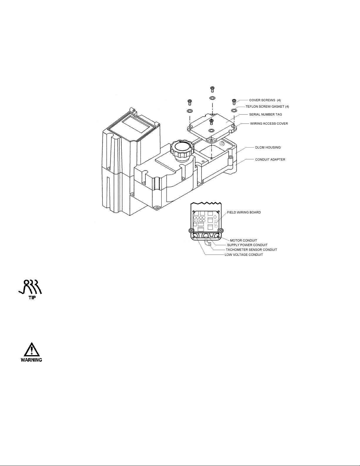
The field wiring of the DLCM is accomplished through a rear access cover at the back of the unit –
near the PULSAR gearbox and motor. The access panel is opened by removing the 4 retaining screws
(Phillips head screw driver required). Removal reveals the Field Wiring Board (refer to Figure 2).
Figure 2 – Accessing the Field Wiring Board
The Field Wiring Access Cover has the Serial Number Tag on it. Keep the cover with the DLCM it
was removed from. The DLCM is marked internally with the Serial Number. The internal marking
will be used for warranty claims.
The Field Wiring Board (refer to Figure 2) contains wiring blocks for making all of the electrical
connections. It is mechanically attached to the Conduit Adapter. The adapter in conjunction with the
Field Wiring Board form a modular connector or plug. This allows the DLCM to be removed from the
PULSAR unit without disturbing the conduit connections.
R
EMOVE THE CONDUIT ADAPTER AND FIELD WIRING BOARD FOR
PURPOSES ONLY
(
REFER TO SECTION
12 – B
ASIC REPAIRS) FOR FURTHER INFORMATION
DLCM
REPAIR/REPLACEMENT
.
7
Page 14

5.3.2 Finding your way around the Field Wiring Board
The electrical connections are segregated on the Field Wiring Board. The high voltage connections are
on the right-half side while the low voltage connections are on the left. Refer to Figure 3, Field
Wiring Board for specific connection and fuse locations.
Figure 3. Field Wiring Board
8
Page 15
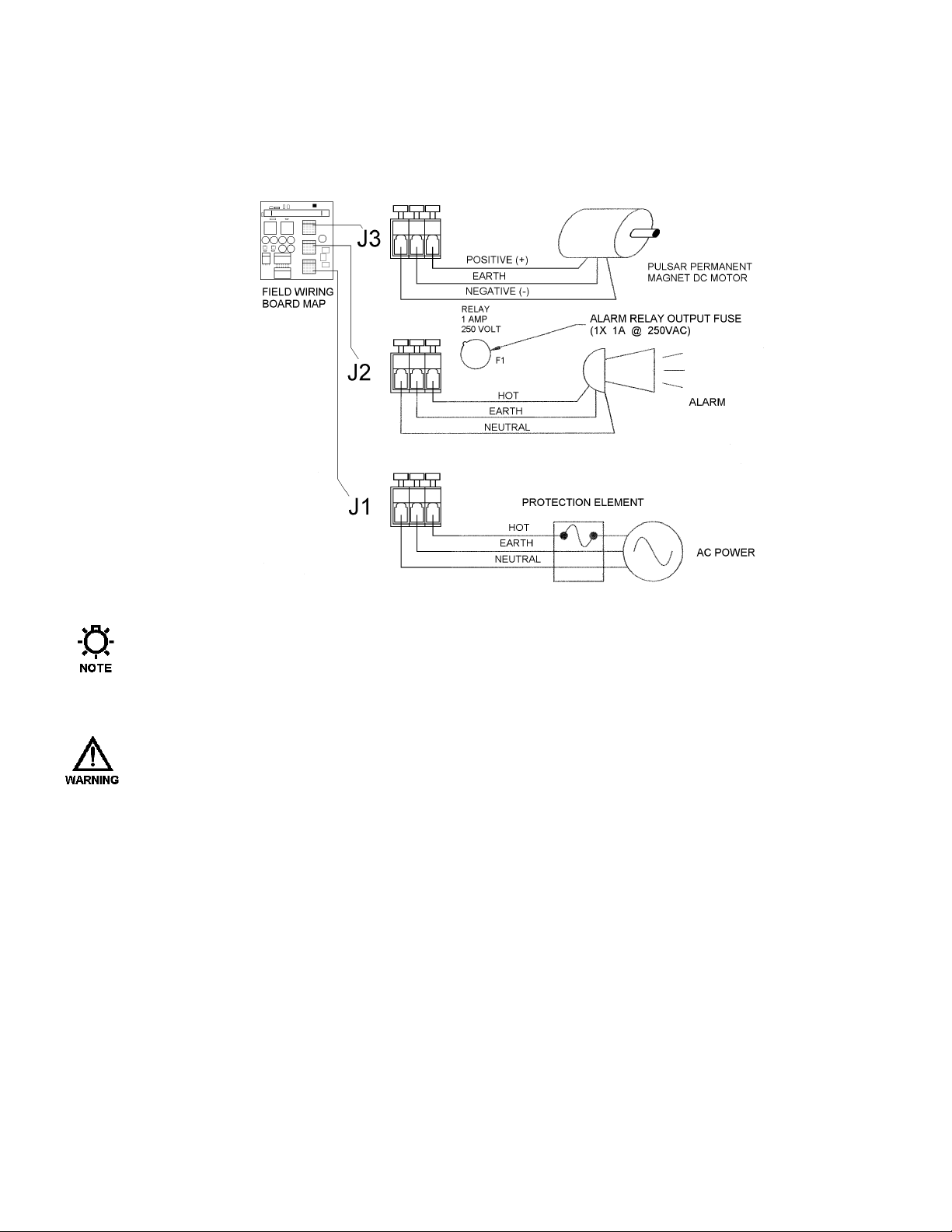
5.4 High Voltage Connections
There are only three high voltage connections to be made on the DLCM: supply power (J1), PULSAR
motor load (J3), and Alarm Relay Load (J2). Only the supply power and PULSAR motor load
connections are required. Refer to Figure 4 for connection location.
The Positive (+) and Negative (-) wires may not be labeled. Do not be concerned with polarity when
hooking up the motor. It does not matter what direction the motor rotates.
5.4.1 Supply Power
T
DLCM
HE
CONNECTION TO POWER ITS OWN SUPPLY
OUTPUT
BRANCH CIRCUIT
The DLCM power supply and attached PULSAR motor are not fuse protected. You are responsible for
correctly sizing the protection element (i.e., fuse or circuit breaker at the distribution panel). Use the
work sheet on the next page for correctly sizing the branch protection element.
REQUIRES ONE CONNECTION TO AN EXTERNAL POWER SOURCE
. Y
OU MUST TAKE THESE EXTERNAL LOADS INTO CONSIDERATION WHEN SIZING THE
.
Figure 4 – High Voltage Connections
,
DC
THE
PUMP MOTOR AND THE ALARM RELAY
. I
T USES THIS SAME
9
Page 16
The DLCM with an attached pump motor and alarm load, should be connected to its own branch
circuit. Size the supply wire and protective element according to local code requirements. Use 14
AWG, 105° C insulation wire or better. Attach the supply to the J1 terminal block labeled 'LINE
POWER IN'. Make 3 connections: Neutral, Earth (ground) and Hot as labeled.
115VAC +/- 10% 50/60Hz 230VAC +/- 10% 50/60Hz
Device Current Requirement (Amp) Device Current Requirement (Amp)
DLCM 1A (1A Max.) DLCM .5A (.5A Max.)
Pump Motor* + (8A Max.) Pump Motor* + (4A Max.)
Alarm Relay* + (1A Max.) Alarm Relay* + (1A Max.)
Total ** = Total ** =
* In-rush current requirements should be considered. All values RMS.
** Calculation is for guideline purposes only. User must consult local electrical codes when sizing branch
circuits. Protection must not exceed 10Amps RMS at 115VAC or 5.5Amps RMS at 230VAC.
Branch Circuit Protective Element Sizing Worksheet.
The operating voltage and frequency of the DLCM are factory configured – an internal motor and
capacitor are sized according to voltage and frequency. If the power supplied to the unit does not
match the factory configuration, the DLCM will display either an {OVER VOLTAGE} or {UNDER
VOLTAGE} diagnostic message on power-up. This is possible because the microprocessor and
display are powered by a switching power supply. It detects the incoming power and self-regulates its
output. This power supply is protected by a 7.4 Joule surge suppression device. The microprocessor
will not operate the internal stroke adjustment motor, potentially causing damage, until the voltage
problem is corrected.
H
IGH VOLTAGE CIRCUITS (E.G
H
COMBINE
LESS THAN
ELECTRICAL INTERFERENCE THAT MAY RESULT IN IMPROPER
OPERATION
IGH VOLTAGE (I.E
32VDC)
LINES IN A COMMON CONDUIT
.
.,
BRANCH) SHOULD BE RUN IN SEPARATE CONDUIT
.,
GREATER THAN
100VAC)
! F
AILURE TO COMPLY WILL RESULT IN
LINES AND LOW VOLTAGE (I.E
(
AND POSSIBLY UNSAFE
. D
O NOT
.,
)
10
Page 17
5.4.2 PULSAR Motor
In most cases the DLCM is supplied with a factory installed DC motor. If a motor was not supplied, it
is important to select the proper type. Refer to the chart below for acceptable DLCM motors (refer to
Section 9 – Specifications for motor details):
Motors must be permanent magnet, SCR drive rated DC motors. The DLCM cannot control motors
with separate field windings.
Part Number Developed
H/P
For 115 Volt line power
NP500059-000 1/4 hp 90 Volts 2.5 amps TENV
NP500050-000 1/3 hp 90 Volts 3.2 amps TENV
CDPWD3330 1/2 hp 90 Volts 4.8 amps TENV
For 230 Volt line power
CDPWD3306 1/4 hp 180 Volts 1.25 amps TENV
NP500051-000 1/3 hp 180 Volts 1.6 amps TENV
CDPWD3326 1/2 hp 180 Volts 2.5 amps TENV
NP500053-000 1.0 hp 180 Volts 5.0 amps TEFC
Armature
Voltage
Full Load
Current
Enclosure
Type
Connect the permanent magnet DC pump motor to the J3 terminal block labeled 'PUMP MOTOR OUT
AC/DC.' Use 14 AWG, 105° C insulation wire size or larger. If the DLCM supply voltage is
115VAC, you must use a 90Volt Armature motor. If the DLCM supply voltage is 230VAC, you must
use a 180Volt Armature motor.
T
DLCM
HE
ALARM
SUPPLY VOLTAGE TO THE ATTACHED DEVICE
BE DISCONNECTED AT THE MAIN BEFORE WORKING ON ELECTRICAL CONNECTIONS OR ANY
MOVING PUMP COMPONENTS
USES SOLID-STATE RELAYS FOR IT'S HIGH VOLTAGE OUTPUTS (I.E
). I
N THE
'OFF'
STATE, THESE DEVICES TYPICALLY LEAK
(
OR TERMINAL BLOCK
(E.G.,
MOTOR, GEAR TRAIN, ETC
.).
20-30MA
)! T
HE SUPPLY POWER MUST
.,
MOTOR AND
OF CURRENT AT THE
D
OUBLE CHECK ALL CONNECTIONS TO CONFIRM GOOD ELECTRICAL CONTACT BETWEEN THE
. M
TERMINAL BLOCK CLAMP AND BARE WIRE
. I
INSULATION
DIVIDERS BETWEEN TERMINALS
NSURE THAT BARE WIRE IS NOT FRAYED AND DOES NOT RISE ABOVE THE
.
AKE SURE THE CLAMP IS ON THE WIRE, NOT THE
At high motor turndown settings the DC motor can overheat under certain conditions. Non-standard
motors must include built-in thermal protection and a dry contact thermal switch for connection to the
DLCM’s Motor Thermostat input. Refer to Section 5.8 – Motor Thermostat for additional
information.
11
Page 18
5.4.3 Alarm Relay
The Alarm Relay is an output that is configured by the operator. Refer to Section 7 – General
Operation for specific instructions on how to activate the Alarm Relay. The Alarm Relay Load must
not exceed 1 Amp at rated voltage. Connect the Alarm load to the J2 terminal block labeled 'ALARM
RELAY OUT.' Use 22 AWG wire size or larger. Make three connections: Neutral, Earth (ground) and
Hot as labeled.
5.5 Low Voltage Input Connections
There are two types of Low Voltage inputs: Current (e.g., 4-20mA) and Dry Contact. The Low Voltage
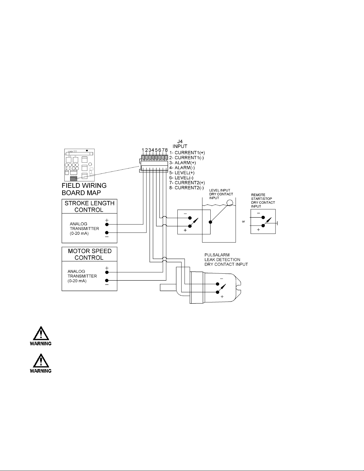
Input connection block is labeled J4 'INPUT' (refer to Figure 5). It contains four pairs of inputs:
Current 1, Alarm, Level and Current 2.
Figure 5 – Low Voltage Input
T
HE DRY CONTACT INPUTS ARE SELF-POWERED
. D
CLOSURE TO ACTIVATE
T
HE WIRE USED TO CONNECT LOW VOLTAGE INPUTS, AND SERIAL COMMUNICATIONS SHOULD
BE RUN IN A CONDUIT SEPARATE FROM THE
V
OLTAGE (I.E
LINES IN A COMMON CONDUIT
INTERFERENCE THAT MAY RESULT IN IMPROPER
.,
GREATER THAN
O NOT ATTACH EXTERNALLY POWERED CIRCUITRY
100VAC)
! F
AILURE TO COMPLY WILL RESULT IN ELECTRICAL
. S
UPPLY ONLY A MECHANICAL SWITCH
H
IGH VOLTAGE POWER
LINES AND LOW VOLTAGE (I.E
(
AND POSSIBLY UNSAFE) OPERATION
. D
.
O NOT COMBINE HIGH
.,
LESS THAN
32VDC)
.
12
Page 19

5.5.1 Analog Inputs
The DLCM can accept either one or two analog input signals. These signals ultimately control the
pump’s flow. Analog Input #1 is used to control either the pump stroke and speed (refer to the note:
below) or the pump stroke only. When Analog Input #2 is used, it controls motor speed only.
The DLCM can operate using only Analog Input #1 to control both Stroke and Motor Speed. If this is
the desired mode of operation, the installed software will determine what Stroke and Speed are required
to produce the desired flow rate (refer to Section 7 – General Operation: End Point Set Up) for further
information.
The Analog input accepts current inputs in the range of 0 to 25mA (e.g., 4-20mA) provided the 'span,'
(the difference between the High and Low value), is greater than 2mA. Voltage signals in the 0-5 volt
range are accepted but displayed as current during Analog Input calibration.
Split-ranging, reverse acting, and ratio control are accomplished in the calibration routine in Section 7
– General Operation. No hardware adjustments are required. The channels are electrically isolated,
surge protected and fused for protection. The inputs are designed to avoid damage in the event high
voltage is inadvertently applied.
To make the Stroke Length Control connection, use 0.32mm2 – 0.52mm2 (22-20 AWG) wire for
hookup. Attach the analog signal generated by an external device (e.g., PLC) to the connection points
labeled '1-CURRENT1(+)' and '2-CURRENT1(-)' on the J4 terminal block labeled 'INPUT' (refer to
Figure 5). Attach the Positive lead to position 1 and the Negative lead to position 2.
To make the Motor Speed Control connection, use 0.32mm2 – 0.52mm2 (22-20 AWG) wire for hookup.
Attach the analog signal generated by an external device (e.g.: PLC) to the connection points labeled '7CURRENT2(+)' and '8-CURRENT2(-)' on the J4 terminal block labeled 'INPUT' (refer to Figure 5).
Attach the Positive lead to position 7 and the Negative lead to position 8.
Position indicators are printed on the circuit board above the terminal. The DLCM will provide
approximately 200 ohms of resistance to a current loop. Each Analog Input is isolated from all other
inputs, outputs and earth ground. Follow the instructions in Section 7 – General Operation for Analog
Input signal calibration and set-up.
13
Page 20

5.5.2 Alarm Input
The Alarm Dry Contact Input is designed to operate with the PULSAlarm leak detection option. It is
software configurable to generate an alarm, activate the alarm relay and/or shut down the PULSAR
motor. The input is internally powered – only a mechanical switch closure is required for activation.
Use 0.32mm
2
– 0.52mm2 (22-20 AWG) wire. Attach one side of the switching device to the position
labeled '3-ALARM(+)' and the other side to the position labeled '4-ALARM(-)' of connector J4-INPUT
(refer to Figure 5). A resistance of 15K ohms or less is required across the two connections for proper
detection. Follow the instructions in Section 7 – General Operation for Alarm Input (Leak Detection)
software set-up.
5.5.3 Level Input (Remote Start/Stop)
The Level Dry Contact Input is designed to monitor a single-point Level Input sensor and generate an
alarm, activate the alarm relay and/or shut down the PULSAR motor. It can also be used with a
Remote Start/Stop station (Dry Contact switch) to start and stop the pump’s motor. The input is
internally powered, only a mechanical switch closure is required for activation. Use 0.32mm
0.52mm
LEVEL(+)' and the other side to the position labeled '6-LEVEL(-) of connector J4-INPUT (refer to
Figure 5). A resistance of 15K ohms or less across the two terminals is required for proper detection.
Follow the instructions in Section 7 – General Operation for Level / Start-Stop set-up.
2
(22-20 AWG) wire. Attach one side of the switching device to the position labeled '5-
2
–
14
Page 21
5.6 Low Voltage Output Connections
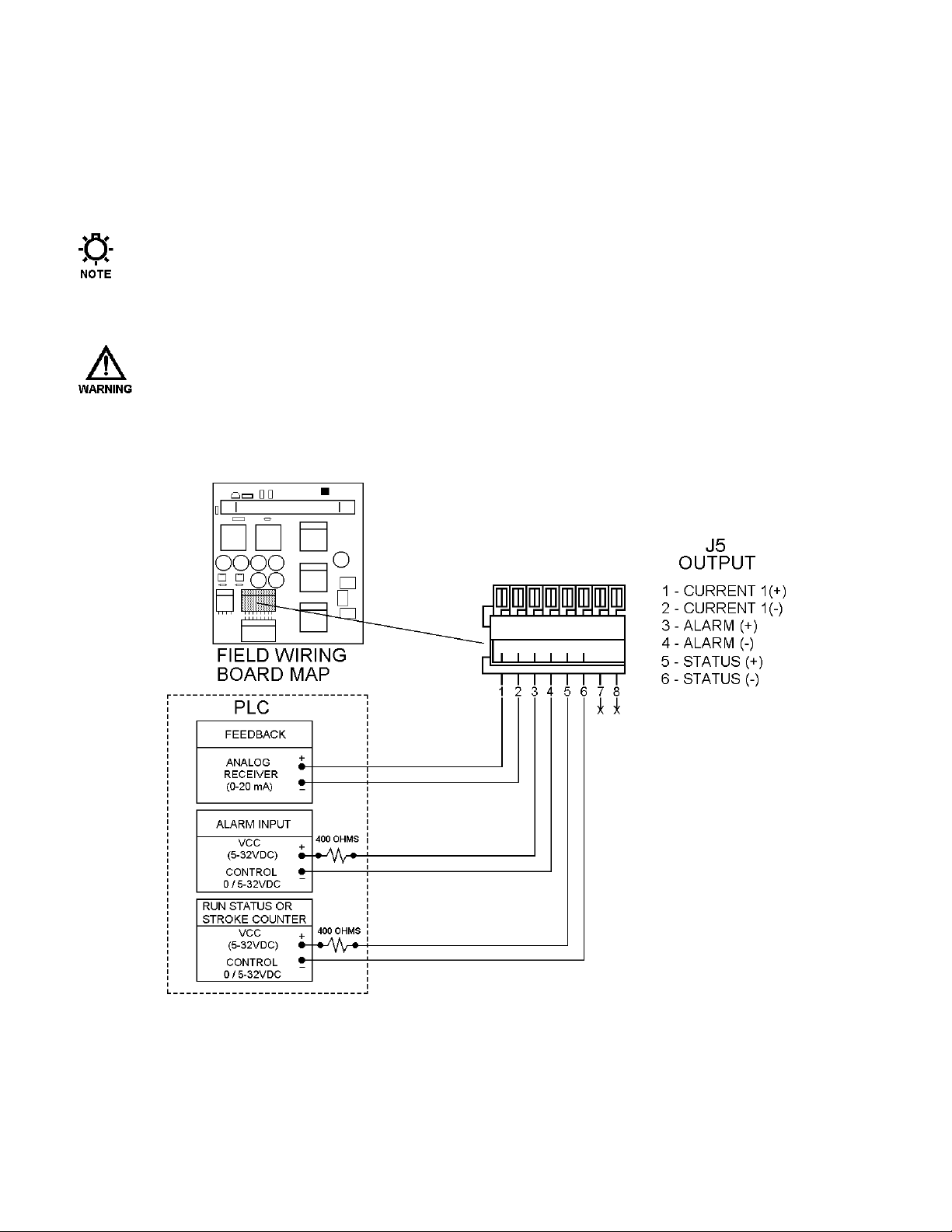
There are two types of Low Voltage outputs: Analog (e.g., 4-20mA) and Transistor based Dry Contact.
The Low Voltage Output connection block is labeled J5 'OUTPUT' (refer to Figure 6). It contains threepairs of outputs: Current, Alarm and Motor Status/Stroke.
The Transistor based Dry Contact outputs are optically isolated. To achieve total isolation, they are
not self powered. The external device must supply and detect a return voltage level (32VDC max).
T
HE WIRE USED TO CONNECT LOW VOLTAGE INPUTS, OUTPUTS AND SERIAL COMMUNICATIONS
SHOULD BE RUN IN A CONDUIT SEPARATE FROM THE
H
COMBINE
THAN
ELECTRICAL INTERFERENCE THAT MAY RESULT IN IMPROPER
OPERATION
IGH VOLTAGE (I.E
32VDC)
LINES IN A COMMON CONDUIT
.
.,
GREATER THAN
100VAC)
! F
AILURE TO COMPLY WILL RESULT IN
H
IGH VOLTAGE POWER
LINES AND LOW VOLTAGE (I.E
(
AND POSSIBLY UNSAFE
. D
O NOT
.,
LESS
)
Figure 6 – Low Voltage Output
15
Page 22

5.6.1 Current Output
The Current Output Channel can follow one of three signals:
a) Calibrated flow
b) Calibrated stroke length
c) True motor speed
It is calibrated to source current in the 0 to 20mA range (e.g., 4-20mA). The output can be calibrated
for reverse acting and split ranging and control. Refer to Section 7 – General Operation: Calibration
for further details.
Current Output is used to control slave devices (e.g., DLCM's, ELMA's, PULSAMATICs, etc.) or to
fulfill closed loop system requirements. Attach the connection points labeled '1-CURRENT(+) and '2CURRENT(-)' on connector J5-OUTPUT (refer to Figure 6) to the external device. Use 0.32mm
0.52mm
2
(22-20 AWG) wire. Attach the Positive lead to position 1 and the Negative lead to position 2.
The analog output will drive against a maximum load of approximately 700 ohms. Thus, a single
DLCM Analog Output could be used to drive two slave DLCM's. They, in turn, could each drive two
additional slaves. The Analog Output is isolated from all other inputs, outputs and earth ground.
Follow the instructions in Section 7 – General Operation: Analog Output Signal Calibration.
5.6.2 Alarm Dry Contact Output
The Alarm output is a solid state transistor closure. It indicates the present state of the alarm relay
output. If the Alarm Relay is on, the Alarm Dry Contact will be closed. If the Alarm Relay is off, the
Alarm Dry Contact will be open. It is commonly used to indicate an alarm status to external control
equipment (i.e., PLC, PC or other Manual controllers). Refer to Figure 6.
2
–
VCC (+5VDC) and Ground are provided on terminals 7 and 8 of connector J5. A 250 ohm resistor
from terminal '7-VCC' to terminal '3-ALARM(+)' will cause a +5VDC signal to appear between
terminals '4-ALARM(-)' and '8-DCGND' when the Alarm Relay is on. This technique is only
recommended if the input on the external device is isolated from all other inputs, outputs and
grounds.
An opto-coupler is used to achieve total isolation of this output. As such, the external control
equipment must generate the supply on the positive output and detect the return of that signal from the
DLCM. In a typical application, use 0.32mm
2
– 0.52mm2 (22-20 AWG) wire to attach the terminal
labeled '3-ALARM(+)' – the collector terminal – to the external equipment's logic supply. Connect the
terminal labeled '4-ALARM(-)' – the emitter terminal – to the positive input of the equipment. The
negative input of the equipment should be connected to its isolated ground. A series resistance of 400
ohms is recommended – especially when sinking current (e.g., a photo-diode of an opto-isolator). The
Alarm output cannot be separately configured in the software, it follows the Alarm Relay output.
16
Page 23
5.6.3 Run Status or Stroke Counter
The Status output can be configured through software to indicate that the pump motor is on or to
generate a pulse with every pump stroke (for use with an external stroke counter). The factory default
for this output is to indicate Pump Motor Status. The Stoke output is not in phase with the pump stroke
but has a 50% duty cycle (e.g., the output is ON for half of the stroke and OFF for the other half.).
An opto-coupler is used to achieve total isolation of this output. As such, the external control
equipment must generate the supply on the positive output and detect the return of that signal from the
DLCM. In a typical application, use 0.32mm
labeled '5-STATUS(+)' – the collector terminal – to the external equipment's logic supply. Connect the
terminal labeled '6-STATUS(-)' – the emitter terminal – to the positive input of the equipment. The
negative input of the equipment should be connected to its isolated ground. A series resistance of 400
ohms is recommended – especially when sinking current (e.g., a photo-diode of an opto-isolator).
There is also an internal stroke counter that is re-settable. Refer to Section 7.2 - Menu –
Diagnostics – Diag. Menu 11/11.
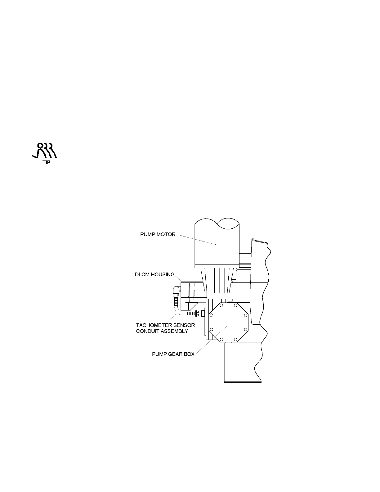
5.7 Tachometer Input
The Tachometer Sensor is connected to the Tachometer Input. It senses motor rotation. This input allows
the DLCM to control motor speed.
2
– 0.52mm2 (22-20 AWG) wire to attach the terminal
Figure 7 – Tachometer Sensor Conduit Assembly
17
Page 24
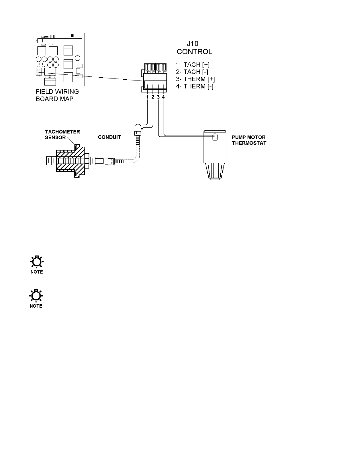
Figure 8 – Tachometer and Pump Motor Thermostat Connections
To connect the Tachometer Input, connect the wire labeled VDC (typically brown) to the connection
point labeled 1–TACH [+] on connector J-10 CONTROL. Connect the wire labeled TACH (typically
blue) to the connection point labeled 2–TACH [-] on connector J-10 CONTROL. Make these
connections using the 22 AWG wire provided with the Tachometer Sensor (refer to Figure 8).
For additional information relating to the Tachometer Sensor, refer to Section 13 – Repairs: DLCM
Replacement.
The Tach input is designed for use with the supplied sensor only. Do not attempt to use any other
device (e.g.: motor based tachometer outputs).
It is permissible to run the pump motor thermostat in the same conduit as the pump motor power.
The signal is conditioned to prevent erroneous operation due to cross-talk.
18
Page 25
5.8 Motor Thermostat
The motor thermostat has been supplied as an equipment safety measure. This allows the DLCM pump
motor to operate without the danger of overheating the motor windings.
In the event that the internal temperature of the motor exceeds the motor manufacturer’s specification,
the DLCM can be configured to:
a) Turn the motor off.
b) Sound an alarm.
c) Restart the motor when the temperature lowers to a safe level.
For more information about the Motor Thermostat settings, refer to Section 7 – General Operation:
Motor Thermostat Setup .
To connect the Motor Thermostat to the DLCM, connect the two thermostat wires (typically these
wires are a smaller gauge wire) coming from the pump motor to the connection point labeled ‘3–
THERM [+]’ and ‘4–THERM [-]’ on connector J–10 CONTROL (refer to Figure 8).
5.9 Serial Communications Input
The Serial Communications input is used to communicate digitally with the DLCM. It allows remote
control and, if so configured, can be used to replace the analog input and output to allow one or more
DLCM’s to be slaved to a single DLC, DLCM, PLC, or PC master.
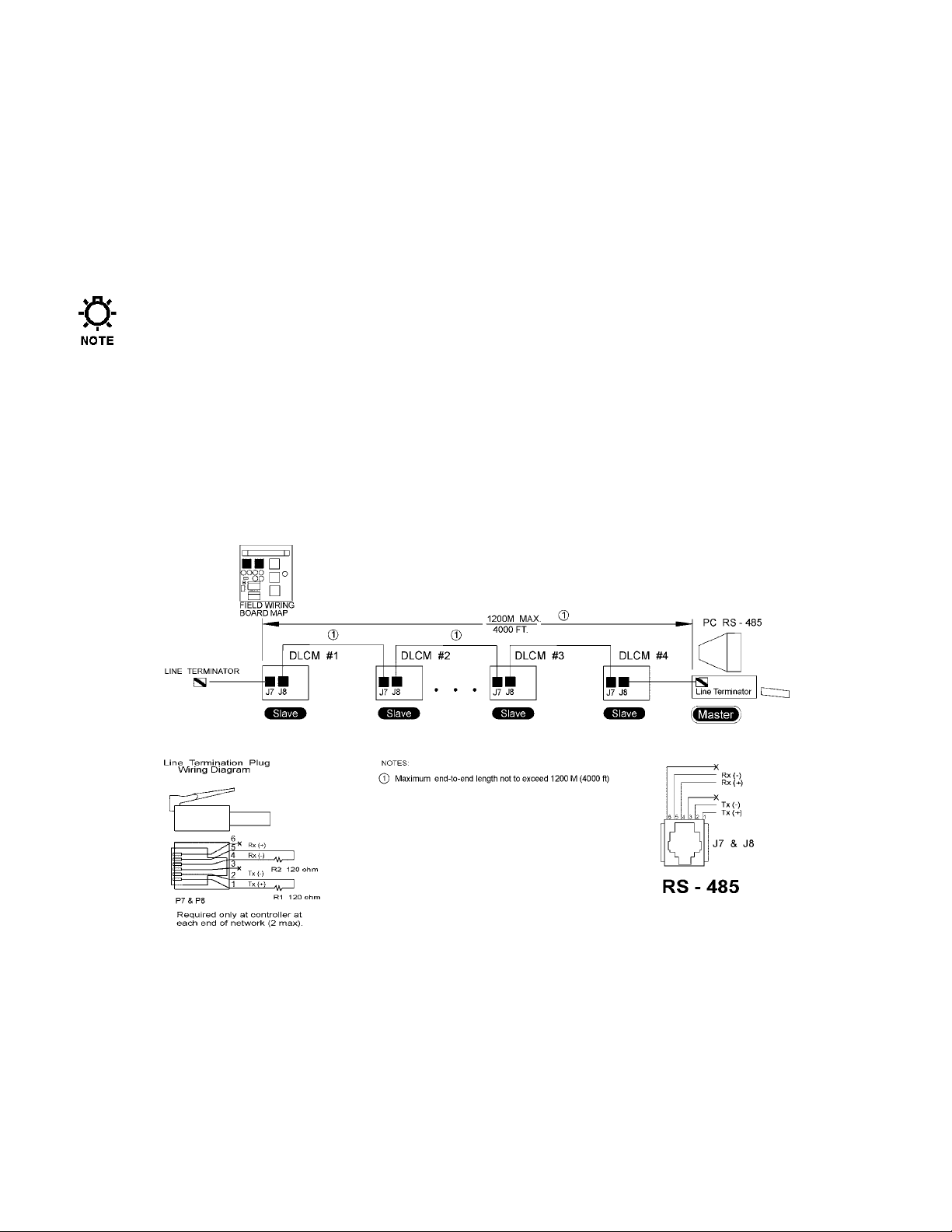
Figure 9 – Typical Serial Communications Connections
Use Belden™ Type 1590A data twist cable or equivalent. RJ-11 connectors (not supplied) are used to
plug into jacks J7 & J8 (refer to Figure 9).
The DLCM uses a 4-wire RS-485 network. This uses two wires for transmit and two wires for receive.
The RS-485 specification limits the total network length to 1200M (4000 ft). It also requires termination
resisters at both the first and last device.
Line Terminators can be constructed according to the drawing above.
19
Page 26
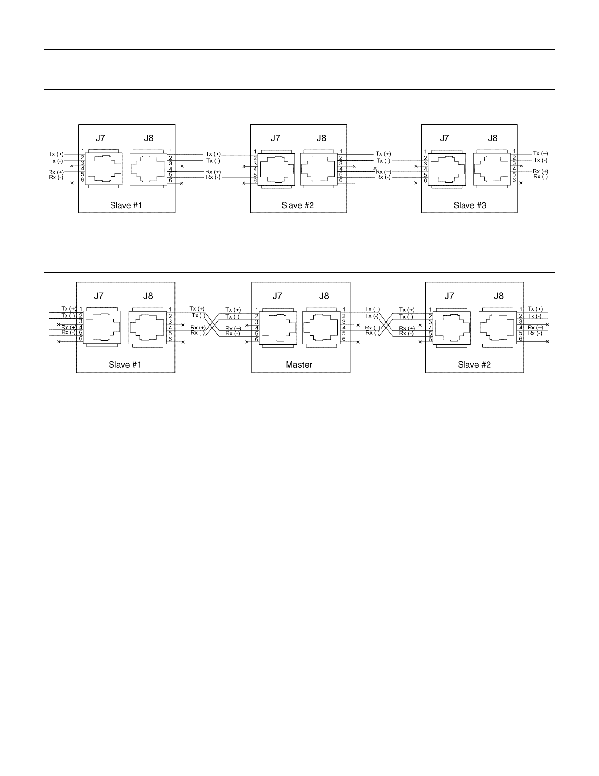
Slave to Slave
When connecting two Slaves, the wiring is straight through. For example: Connect the transmit lines
to the transmit lines and the receive lines to the receive lines (refer to the drawing below).
Master to Slave
When wiring between a Master and a Slave, the Transmit and Receive lines must be crossed. For
example: Connect the transmit lines to the receive lines (refer to the drawing below).
Important Wiring Detail
Figure 10 – Wiring Detail
20
Page 27
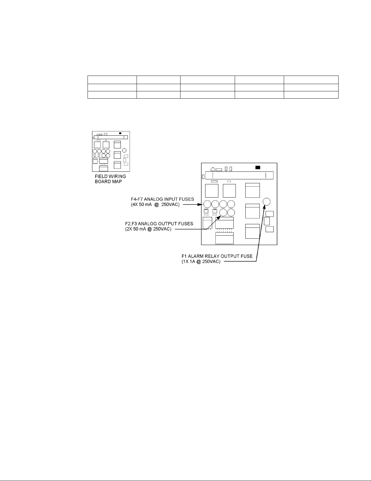
5.10 Fuse Replacement
Although Fuse replacement is not a part of normal installation, it is possible that fuse failure will result
from improper wiring. The DLCM uses a total of 7 user replaceable fuses: 1 for the alarm relay output, 2
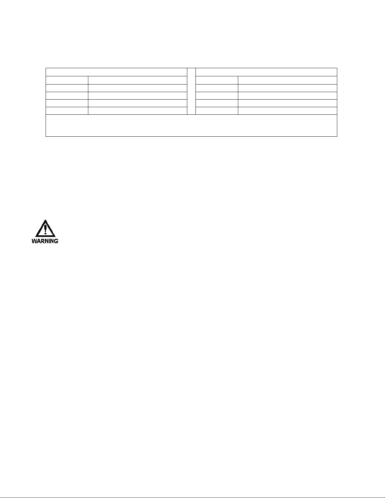
for each of the Current Input and Output Channels. The table below details fuse replacement information:
Designator Function Rating Wickman P/N Pulsafeeder P/N
F1 Alarm Relay 1A @ 250VAC WK4048-ND NP5300026-000
F2-7 Current I/O 50mA @ 250VAC WK3022-ND NP5300027-000
Figure 11 details the location of these fuses on the Field Wiring Board.
Replacement Fuse Information
Figure 11. – Fuse Location.
The Internal DLCM power supply is fused at 2 Amps. This fuse is not user serviceable. The DLCM
Stroke Length Adjustment Synchronous Motor is inherently protected. It can operate continuously in a
locked rotor state. The DLCM also monitors this motor's duty cycle to maintain a 50% balance between
ON and OFF times. The serial ports and the Remote Run Status Output are protected by self-resetting
current limit devices. These components are not user serviceable.
21
Page 28
6. Start Up Instructions
6.1 Overview
Once all electrical connections have been made, your DLCM is ready for Start-up. The following nine
sections detail the procedures required to complete a DLCM start up.
W
HEN POWER IS SUPPLIED TO THE UNIT, LINE VOLTAGE IS PRESENT ON THE FIELD WIRING
B
OARD LOCATED AT THE BACK OF THE UNIT EVEN WHEN THE MOTOR IS
OFF.
D
URING START-UP, IT IS NECESSARY TO RUN THE PUMP MOTOR
. Y
DISCHARGE FROM THE PUMP
-
PUMP DURING START
UP AND CALIBRATION
OU ARE RESPONSIBLE FOR SAFELY DIVERTING FLOW FROM THE
6.1.1 User Interface Familiarization.
There are four key elements that will be useful in starting-up the DLCM:
a) Display
b) Keypad
c) Manual Adjustment Knob
d) Pump Motor.
Refer to Figure 12 to familiarize yourself with the location of these items before proceeding.
. T
HIS WILL CAUSE FLUID TO
.
Figure 12. – Key DLCM start-up elements.
22
Page 29
6.1.1.1 Display:
This is a 2 line by 16 character alpha-numeric Liquid Crystal Display (LCD) located above the
keypad. It is back-lit with a yellow-green light source for easy viewing in dark areas. Its contrast
can be adjusted by using the keypad.
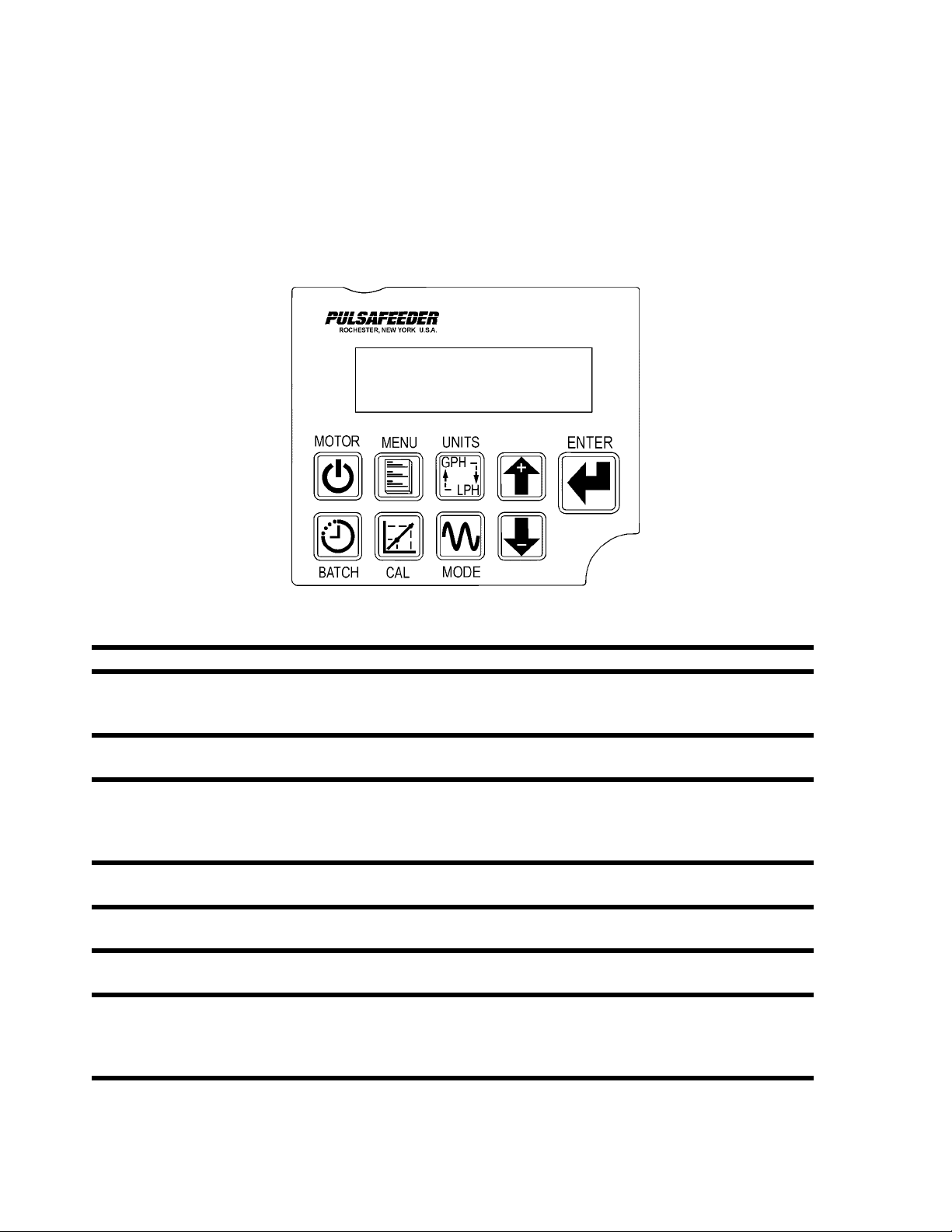
6.1.1.2 Keypad:
The Keypad is a sealed 9-button membrane style input device. It is easy to use and will guide you
quickly to specific functions. Refer to Figure 13 to familiarize yourself with the function of each
key before starting.
MOTOR
MENU
UNITS
ARROWS
ENTER
BATCH
CAL
MODE
Figure 13 – Key Pad
Press this key to Start the PULSAR motor or place it in stand-by.
Press this key to access the Configuration Menu. Press the ARROW keys to scroll
through the Configuration Menu Items. Press [MENU] a second time to exit the
Configuration menu to the current operating mode (e.g., MANUAL MODE).
Press this key to cycle to the next flow unit type whenever a flow unit is displayed at
the operating mode (e.g., MANUAL MODE).
These keys are used to change values currently displayed on screen. Use [DOWN]
to decrease the value and [UP] to increase it. Pressing both [UP] and [DOWN]
simultaneously performs special editing and by-pass functions. This is described
further in Section 7 – General Operation.
Use this key to accept a flashing value or parameter and proceed to the next submenu screen.
This key is used to activate the [BATCH] processing menu. Press [BATCH] a second
time to exit the Batch Setup function.
Press [CAL] to activate the Calibration menu for Flow and Analog Signals. Press
[CAL] a second time to exit the Calibration function.
The [MODE] key is used to change the operating mode of the DLCM. For example,
press once to change from MANUAL to ANALOG. Press a second time to change
from ANALOG to MODBUS. Press a third time to change from MODBUS back to
MANUAL.
23
Page 30
6.1.1.3 Manual Adjustment Knob:
The manual adjustment knob is mechanically attached to the PULSAR stroke length adjustment
mechanism. The DLCM uses the shaft attached to this knob to make its automatic adjustments.
Visually, the knob is a good indication of what the DLCM is doing. For example, if the DLCM is
increasing the pump stroke length – moving from 0 to 100% -- the knob will turn counter-clockwise
until the desired position is achieved.
If you try to force the adjustment, the DLCM will automatically react to adjust the position to the
programmed setting. If you manually adjust the knob while performing a pump calibration, the
calibration session will be terminated
While in the Analog Signal or MODBUS Mode – any attempts you make to change the stroke setting
using the Manual Control Knob to a value other than that specified by the remote signal will cause the
DLCM to make a correction.
The Manual Adjustment Knob should not be adjusted while power is removed from the DLCM. If
the knob is moved while the DLCM power is out, upon re-starting the DLCM will detect the
movement and perform a Zero Calibration .
W
HEN THE
{CALIBRATING ZERO}),
Z
ERO CALIBRATION THE
INTERVENTION COULD CAUSE THE
RESULT IN AN IMPROPER CALIBRATION
DLCM
IS PERFORMING A ZERO CALIBRATION (THE DISPLAY WILL READ
DO NOT TO TOUCH THE MANUAL ADJUSTMENT KNOB
DLCM
IS SEARCHING FOR A HARD MECHANICAL STOP
DLCM
TO INCORRECTLY DETECT THIS STOP
.
You may notice that when adjusting from a lower to a higher value (e.g., 10% to 20%) the DLCM
appears to 'over-shoot' its destination and reverse direction for approximately 1/16 of a revolution.
This behavior is normal. The DLCM always approaches a new position from the same direction to
eliminate backlash in the stroke adjustment mechanism.
6.1.2 Check Wiring and Close Access cover
Double check all of your electrical connections. Pay attention to polarity of all inputs and outputs –
both low and high voltage. Additionally, insure that all clamp style terminals are clamping onto the
bare conductor, not on its insulation.
Replace the wiring access cover and its 4 retaining screws with associated washers.
Use a screwdriver to tighten the retaining screws evenly. Failure to do so may cause the cover to leak
and void the Warranty. The supplied teflon washers are required to properly seal this cover. Failure
to replace these components will void the warranty.
. D
. A
NY MANUAL
. T
HIS WILL
URING A
24
Page 31

6.1.3 Confirm Correct Incoming Power
Double check that the wiring access cover is on and tightened down. Whenever power is supplied to
the DLCM, the display's back-lighting will 'glow' with a yellow-green light. The presence of this backlighting is an excellent indication that the DLCM's incoming power has been wired successfully and
voltage is present. Characters may or may not appear on the display. This is normal and will be
covered in the next section.
W
ITHOUT PRIOR OPERATING KNOWLEDGE, IT IS IMPOSSIBLE TO TELL IF THE
WILL RUN WHEN POWER IS APPLIED TO THE
NECESSARY STEPS TO ENSURE THAT ALL ASPECTS OF SAFETY HAVE BEEN CONSIDERED
ELECTRICAL, HYDRAULIC, ETC
APPLYING POWER
.
.). I
F IN DOUBT, DISCONNECT THE MOTOR FROM
DLCM. Y
The DLCM detects any adjustments made to manual adjustment knob while its power is off. If it
detects that the knob position has been changed, it will perform a zero calibration when the motor is
started. This action is normal.
Turn on power at the main. If the DLCM's incoming power is connected correctly, the back-lighting
on the DLCM's display will illuminate (depending on lighting conditions, it may be necessary to shade
the display to confirm illumination). If the display is not illuminated, first check the line voltage with a
volt meter. If the voltage is not correct, return to Section 5 – Installation: High Voltage Connections.
Otherwise, proceed with the next step.
6.1.4 Confirm Display and Keypad functionality
The example display messages are shown in English for demonstration purposes. If an alternate
language has been set, the text is displayed as a translation of the English version.
Now that you have confirmed that the DLCM is receiving power, it is necessary to confirm that the
display and keypad are functioning properly. On normal power-up, the {SELF-TEST} display appears
for approximately 5 seconds. After that time, the display will change the message to one of the
following:
PULSAR
OU ARE RESPONSIBLE FOR TAKING THE
MOTOR
(E.G.,
J3
PRIOR TO
SELF-TEST
1.20
10.0%
MANUAL MODE
- or -
- or -
TURN MOTOR ON
CALIBRATING ZERO
BATCH#1 RUNNING
10.0%
- or -
- or -
PLEASE WAIT
CALIBRATING ZERO
MOTOR STOPPED
- or -
At this time, the actual message is not important, the characters should be visible and form a reasonable
message.
If the display is blank (no-characters) then the display contrast must be adjusted. This is accomplished
by pressing and holding [MENU] while simultaneously pressing [UP]. This will darken the display.
Be patient! You may have to hold both keys down for as long as 30 seconds before the characters will
become visible. If the display is too dark, press [MENU] and [DOWN] simultaneously to decrease
(lighten) the contrast. Once the contrast is properly adjusted, check the message displayed. If it does
not look similar to one of those shown above, proceed directly to the next section to perform a Factory
Re-initialization on your DLCM.
25
Page 32

The keypad can be tested by depressing each key separately. Most, but not all keys will cause the text
on the display to change. Do not be alarmed if a single key does not invoke a change to the display.
This is normal. Different keys become active/inactive depending on the current operating mode .
There are a number of functions that the DLCM performs (e.g., zero calibration) where the keypad has
no effect. If the stroke adjustment knob is not moving, at least one key on the key pad should cause the
text on the display to change. Go to Section 6.1.6. If this is not the case, refer to Section 11 – Trouble
Shooting.
6.1.5 Performing a Factory Re-initialization
When Re-initializing your DLCM, all of the system settings will be overwritten by the original factory
default settings. The controller must be re-configured to your specifications (e.g., re-calibrated).
If your DLCM appears to be functioning properly – the display is similar to one of those shown on the
previous page – skip to Section 6.1.6.
A Factory Re-initialization restores all factory defaults to the DLCM's memory, and typically is not
required.
A Factory Re-initialization should be performed only if there is reason to believe that the internal
DLCM memory has become corrupted. A number of factors could cause this including: long-term
storage, disregard of electrostatic precautions (refer to Section 2 – Safety) during installation, improper
wiring, voltage surges, etc. The condition usually manifests itself with inconsistent or erratic operation
– often associated with characters on the display. Depending on the state of your DLCM, use one of
the following procedures:
Start-up Factory Re-Initialization:
Use this procedure when you cannot read the display, or if the DLCM does not seem to be responding
to your key presses:
1. Cycle power to the unit (turn it OFF then ON).
2. Within the first 5 seconds of power on, depress and hold the [UNITS], [MODE], and [ENTER]
keys simultaneously for approximately 1 second.
3. The display will continue to display the version number while the DLCM’s memory is restored.
The display will then show {TURN MOTOR ON / CALIBRATING ZERO}. Return to Section
6.1.4. Confirm the display and keypad are functioning properly.
26
Page 33

Menu Factory Re-initialization:
Use this procedure if the display and key pad appear to be functioning properly, but you suspect other
problems with data corruption, erratic operation, etc. Factory Re-initialization can be found in the
Configure Menu. Perform the following steps:
1. Apply power to the unit. Wait for the {SELF-TEST} display to disappear. The unit should display
a standard power on screen.
2. Press [MENU]. The display will show the first menu item {DIAGNOSTICS}.
3. Press [DOWN]. The {FACTORY DEFAULTS} menu item should be displayed. If not, continue
pressing [DOWN] until it does.
4. Press [ENTER]. The prompt {FACTORY RESET? / NO} is displayed.
5. Press [UP]. The prompt will read {FACTORY RESET? / YES}.
6. Press [ENTER] to accept the {YES} prompt. The prompt {ARE YOU SURE? / NO} is displayed.
7. Press [UP]. The prompt will read {ARE YOU SURE? / YES}.
8. Press [ENTER] to accept the {YES} prompt.
9. The display will read {PLEASE WAIT} for approximately 5 seconds while the DLCM’s memory
is restored. The display should then display {TURN MOTOR ON / TESTING ENCODER}.
Return to Section 6.1.4. Confirm the display and keypad are functioning properly.
6.1.6 Test Pump Motor
The Level Input, PULSAlarm and Signal Loss inputs can be configured to shut the motor down if
they are enabled. If this is the case, a message is displayed on the screen indicating the failure. You
cannot re-start the motor until these inputs have been corrected or the {Motor Off} option has been
disabled. Refer to Section 7 – General Operation for further information on configuring these
options.
To test the PULSAR motor connection, press [MOTOR]. If the motor is running it should stop and the
display should read {MOTOR STOPPED} or {TURN MOTOR ON / CALIBRATING ZERO} or
{TURN MOTOR ON / TESTING ENCODER} as shown below.
MOTOR STOPPED
If the motor is stopped, press [MOTOR] to start it and set the unit in Operating Mode. The display
should then read {MANUAL MODE} or {BATCH#X RUNNING} or {PLEASE WAIT /
CALIBRATING ZERO} as shown below.
10.0%
MANUAL MODE
If the display appears as shown above, but the PULSAR motor does not start, return to Section 5 –
Installation: High Voltage Connections and check your wiring. If the wiring is correct, refer to
Section 11 – Trouble Shooting.
The motor speed may be low enough that it is hard to tell that it is running. Check for fluid
discharge.
- or -
- or -
TURN MOTOR ON
CALIBRATING ZERO
BATCH#1 RUNNING
10.0%
- or -
- or -
TURN MOTOR ON
TESTING ENCODER
PLEASE WAIT
CALIBRATING ZERO
27
Page 34

6.1.7 Set Time and Date
The clock on your DLCM has been activated at the factory, but you should set it to the local time and
date of the installation site.
Time and Date are set in the Configuration Menu. Below is an example that accepts some software
default values:
1. From the Current Operating Mode Display, press [MENU]. The {–MENU– / DIAGNOSTICS-0}
screen is displayed (refer to illustrations below).
2. Press [UP] one time. The {–MENU– / SET TIME AND DATE} screen is displayed.
3. Press [ENTER]. The date and time screen is displayed.
4. Press [ENTER] to accept the 24 Hour time setting.
5. Press [UP] or [DOWN] to adjust the hour value displayed to the local time. Press [ENTER].
6. Press [UP] or [DOWN] to adjust the 10 minute value displayed to the local time. Press [ENTER].
7. Press [UP] or [DOWN] to adjust the minute value displayed to the local time. Press [ENTER]
twice (to accept the default MM/DD/YY format setting).
8. Press [UP] or [DOWN] to adjust the month value displayed to the current month. Press [ENTER].
9. Press [UP] or [DOWN] to adjust the day value displayed to the current day. Press [ENTER].
10. Press [UP] or [DOWN] to adjust the year value displayed to the current year. Press [ENTER]
twice (accepting the default Daylight Savings NO setting).
The time and date information has now been set.
-MENU-
DIAGNOSTICS – 0
Press
[UP]
-MENU-
SET TIME AND DATE
Press
[ENTER]
24 HR MM/DD/YY
21:07 1/22/01
Refer to Section 7 – General Operation: Set Time and Date for more detailed instructions on how to set
the Time and Date information.
28
Page 35

6.1.8 Flow Calibration (1-point).
Your DLCM is factory calibrated at rated flow and pressure (1-point). Nevertheless, you should
always perform a calibration with the PULSAR DLCM installed in your system. The only item
required to calibrate your DLCM is a means to measure the output of the pump (i.e., calibration
column, graduated cylinder, etc.). The following is a minimal procedure for performing a 1-point
calibration.
1. Press [MOTOR] to start the motor (if the motor is not currently running).
2. Press [UNITS] repeatedly until a unit that is consistent with your flow measurement device (i.e.,
calibration column) appears. For example, if your column reads in Liters then set the display to
LPM or LPH. Liters will be used in this example.
3. Press [CAL]. The {CALIBRATE / PUMP FLOW} screen is displayed.
4. Press [ENTER]. The {LAST FLOW CAL / 11:32 1/22/01} screen is displayed.
5. Press [ENTER]. The {FLOW CALIBRATION / 1-POINT} screen is displayed.
6. Press [ENTER]. The {CALIBRATE ZERO? / YES} screen is displayed.
If you are confident with the quality of your zero calibration, press [UP] and the {CALIBRATE
ZERO? / NO} screen is displayed. Press [ENTER] and continue with step 10.
7. Press [ENTER]. The {TURN MOTOR ON / TESTING ENCODER} screen is displayed, or if the
pump motor was ON when you started the calibration process, the {PLEASE WAIT / TESTING
ENCODER} screen is displayed.
8. Turn the pump motor on if necessary and the encoder performs its self test. When the self test is
completed, the{PLEASE WAIT / CALIBRATING ZERO} screen is displayed. The DLCM will
adjust the stroke to the 0% position and the motor speed to 100%.
9. When the zero calibration is complete the {PLEASE WAIT / MOTOR CAL.} screen is displayed.
PLEASE WAIT
MOTOR CAL.
With the stroke set at 0% the motor will run at 100% for a few seconds, and then decrease speed to
5%.
It will take anywhere from approximately 10 seconds to 5 minutes to complete the speed change. If
your pump continues to run after 5 minutes there is an error and you should contact Technical
Services.
10. The {PLEASE WAIT / XX% 100%} screen is displayed. The DLCM will adjust the stroke to the
100% position. The PULSAR motor will shut off.
PLEASE WAIT
XX% 100%
11. The {ENTER TO START/ 100% 2.641718 G} screen is displayed. The value '2.641718'
represents the amount of fluid discharged over 60 seconds the last time a calibration was performed
at the 100% stroke setting. Record the fluid base reading from your calibration column.
12. Press [ENTER]. The PULSAR motor will start to run. A timer is displayed counting down from
60 seconds. After 60 seconds the motor will stop automatically.
TIMER: XX SEC
2.641718 G
13. The {ENTER VALUE 100% / 2.641718 G} screen is displayed. Calculate the measured volume
displaced from the calibration column and enter the new value one position at a time using [UP]
and [DOWN] to change an individual position. Press [ENTER] to move the cursor to the next
position.
29
Page 36

14.
Pressing [ENTER] on the last position will cause the {CONFIRM CHANGE? / YES} screen to be
displayed. Press [ENTER] to accept. Your 1-point calibration is now complete.
Refer to Section7 – General Operation: Calibration, Pump Flow for more detailed instructions on
how to perform DLCM calibration.
6.1.9 Analog Input Calibration.
If you are not using the 0-20mA input to the DLCM for control, skip this section. To calibrate the
Input Current you must first correctly wire an external signal source. Refer to Section 5 – Installation:
Low Voltage Input Connections, Analog Input. To perform a calibration, the signal generating device
(e.g., PLC) must be powered up and capable of altering its output from minimum to maximum signal.
6.1.9.1 One – Signal Analog Input Calibration
The following is a minimal procedure for calibrating the Analog Input if the 1 – Signal option is to be
used.
1. Press [CAL]. The {CALIBRATE / PUMP FLOW} screen is displayed.
2. Press [UP]. The {CALIBRATE / ANALOG IN} screen is displayed.
3. Press [ENTER]. The {0% = 4.0mA / 100% = 20.0mA} screen is displayed. These values represent the
previous calibration.
4. Press [ENTER]. The {INPUT ANALOG MIN / 0% = XXmA} screen is displayed. Adjust your PLC
to output a minimum signal (i.e., 4.0mA). The DLCM display will update as the incoming signal
changes.
5. When the displayed value stabilizes, press [ENTER] to accept it. The {INPUT ANALOG MAX /
100% = XXmA} screen is displayed. Adjust your PLC to output a maximum signal (i.e., 20.0mA).
Again, the DLCM display will update with the changing signal.
6. When the displayed value stabilizes, press [ENTER] to accept it. The {INPUT RATIO / 100% =
XX.XmA} screen is displayed.
7. Press [ENTER] to accept the 100% Ratio setting. The {CONFIRM CHANGE? / YES} screen is
displayed.
8. Press [ENTER]. Analog input calibration is now complete.
Refer to Section 7-General Operation: Analog Input Signal Calibration for more detailed instructions
on how to perform Analog Input calibration.
6.1.9.2 Two – Signal Analog Input Calibration
To calibrate a 2 Signal Analog Input, the DLCM factory default must first have been changed from
{STROKE & SPEED / 1-SIGNAL} to {STROKE & SPEED / 2-SIGNALS}. Refer to Section 7 –
General Operation: {–MENU– / Analog Mode} for information on configuring the Analog Mode.
The following is a minimal procedure for calibrating the Analog Input if the 2 – Signals option is to
be used.
1. Press [CAL]. The {CALIBRATE / PUMP FLOW} screen is displayed.
2. Press [UP]. The {CALIBRATE / ANALOG IN} screen is displayed.
3. Press [ENTER]. The {CALIBRATE / STROKE POSITION} screen is displayed.
4. Press [ENTER]. The {0% = 4.0mA / 100% = 20.0mA} screen is displayed. These values represent the
previous calibration.
5. Press [ENTER]. The {INPUT ANALOG MIN / 0% = XXmA} screen is displayed. Adjust your PLC
to output a minimum signal (i.e., 4.0mA). The DLCM display will update as the incoming signal
changes.
30
Page 37

6.
When the displayed value stabilizes, press [ENTER] to accept it. The {INPUT ANALOG MAX /
100% = XXmA} screen is displayed. Adjust your PLC to output a maximum signal (i.e., 20.0mA).
Again, the DLCM display will update with the changing signal.
7. When the displayed value stabilizes, press [ENTER] to accept it. The {INPUT RATIO / 100% =
XX.XmA} screen is displayed.
8. Press [ENTER] to accept the 100% Ratio setting. The {CONFIRM CHANGE? / YES} screen is
displayed.
9. Press [ENTER]. The DLCM is returned to the original operating mode.
10. Press [CAL]. The {CALIBRATE / PUMP FLOW} screen is displayed.
11. Press [UP]. The {CALIBRATE / ANALOG IN} screen is displayed.
12. Press [ENTER]. The {CALIBRATE / STROKE POSITION} screen is displayed.
13. Press [UP]. The {CALIBRATE / MOTOR SPEED} screen is displayed.
14. Press [ENTER]. The {0% = 4.0mA / 100% = 20.0mA} screen is displayed. These values represent the
previous calibration.
15. Press [ENTER]. The {INPUT ANALOG MIN / 0% = XXmA} screen is displayed. Adjust your PLC
to output a minimum signal (i.e., 4.0mA). The DLCM display will update as the incoming signal
changes.
16. When the displayed value stabilizes, press [ENTER] to accept it. The {INPUT ANALOG MAX /
100% = XXmA} screen is displayed. Adjust your PLC to output a maximum signal (i.e., 20.0mA).
Again, the DLCM display will update with the changing signal.
17. When the displayed value stabilizes, press [ENTER] to accept it. The {INPUT RATIO / 100% =
XX.XmA} screen is displayed.
18. Press [ENTER] to accept the 100% Ratio setting. The {CONFIRM CHANGE? / YES} screen is
displayed.
19. Press [ENTER]. The 2 – Signals Analog Input Calibration is complete. The DLCM is returned to its
original operating mode.
20. Refer to Section 7 – General Operation: Analog Input Signal Calibration, for more detailed
instructions on how to perform Analog Input calibration.
6.2 Wrapping up.
Your PULSAR DLCM is now commissioned for use. Refer to Section 7 – General Operation for
specific instructions on how to access your DLCM's advanced features. Please don't be intimidated by
your DLCM, take time to explore and experiment with its features. Remember, you cannot configure
the software in a way that would damage the DLCM. Typically, whenever you are about to set a
critical value (e.g., Calibrate Flow), you are always prompted to confirm your change before it takes
effect. If you are ever dissatisfied with the configuration of your DLCM, you can always return to the
Factory Defaults by repeating Section 6.1.5.
31
Page 38
7. General Operation
This section covers the General Operation of the DLCM as it relates to software. It includes detailed
instructions and example screens. The default values of the DLCM have been set at the factory. You can
over-ride these settings to tune the DLCM to your particular needs.
7.1 General Operation Instructions
7.1.1 Pump Flow Calibration
Pulsafeeder recommends performing at minimum a Two-Point flow calibration on every PULSAR
DLCM installed. Maintenance re-calibration should be performed periodically – at least every three to
four months – to account for component wear. Re-calibration of the pump is also recommended
whenever wet-end components are replaced.
The DLCM does not automatically compensate for changing system conditions (e.g., discharge
pressure, fluid viscosity, etc.). You should re-calibrate whenever the application conditions change.
All flow calibrations are performed at 100% motor speed. The calibration process affects the Stroke
Adjustment mechanism only. The DLCM self-calibrates its motor speed.
Multi-point Calibration Procedure
1. Press [CAL] to enter the Calibration Menu. Press [ENTER] to go to the calibrate pump flow sub-
menu:
CALIBRATE
PUMP FLOW
2. The DLCM displays the last time the pump was calibrated. Press [ENTER] to continue with pump
flow calibration.
LAST FLOW CAL
3:25 1/22/01
3. The display shows {FLOW CALIBRATION / 1 POINT}. The '1 POINT' text will be flashing.
FLOW CALIBRATION
1 POINT
Press [UP] to change flow calibration to 2 points, 3 points, 4 points or 5 points. The calibration points
correspond to the following stroke length values:
1 point: 100% 4 points: 10, 25, 50 and 100%
2 points: 10 and 100 % 5 points: 10, 25, 50, 75 and 100%
3 points: 10, 50 and 100%
A One – point calibration should be avoided in applications where the displayed flow rate is critical.
For discharge pressures less than 500 psi (34.5 Bar), a minimum 2 – point calibration is
recommended. For discharge pressures above 500psi (34.5 Bar) a minimum 3 – point calibration is
recommended.
Press
[ENTER]
Press
[ENTER]
Press
[UP]
These percentage values correspond to the API standards. If you continue to press [UP] you will also
see the following options: {CHANGE CONSTANTS} and {TUNE}. These options are for use after a
multi-point calibration has been performed. For a standard multi-point calibration, set the number of
calibration points to use and press [ENTER] to continue.
32
Page 39

You can "skip" a calibration point by entering a flow value of 0.0000. “Skipping” a point means that
it will be omitted from the mathematical regression to establish the flow curve. Values which are less
than 10% of the pumps’ rated output flow should be skipped.
4. Press [ENTER]. The {CALIBRATE ZERO? / YES} screen is displayed.
CALIBRATE ZERO?
YES
Press
[ENTER]
If you are confident with the quality of your zero calibration, press [UP] and the {CALIBRATE
ZERO? / NO} screen is displayed. Press [ENTER] and continue with step 8.
5. Press [ENTER]. The {TURN MOTOR ON / TESTING ENCODER} screen is displayed, or if the
pump motor was ON when you started the calibration process, the {PLEASE WAIT / TESTING
ENCODER} screen is displayed.
TURN MOTOR ON
TESTING ENCODER
– or –
PLEASE WAIT
TESTING ENCODER
6. Turn the pump motor on if necessary and the encoder performs its self test. When the self test is
completed, the{PLEASE WAIT / CALIBRATING ZERO} screen is displayed.
PLEASE WAIT
CALIBRATING ZERO
7. The DLCM will now perform a ZERO CALIBRATION. First, it will turn on its motor and adjust its
speed to 100%. Then it will test the encoder's position by increasing the stroke adjustment mechanism
2%. Then the DLCM will adjust in the opposite direction until it reaches the mechanical zero stop (0%
stroke setting). This ensures that the positioning mechanism is working properly and calibrations will
be accurate. The screen will display one of four messages:
PLEASE WAIT
CALIBRATING ZERO
- or -
TURN MOTOR ON
TESTING ENCODER
PLEASE WAIT
MOTOR CAL.
- or -
ENCODER ERROR
PRESS ENTER
If the {TURN MOTOR ON…} screen is displayed, start the PULSAR motor by pressing [MOTOR].
The DLCM will adjust to the 100% position. If you get the {ENCODER ERROR..} screen, refer to
Section 11 – Trouble Shooting Guide.
8. The following screen is displayed.
PLEASE WAIT
XXX.X% 100%
If you get the {PRESS ENTER / TO START MOTOR} screen, start the PULSAR motor by pressing
[ENTER] or [MOTOR].
The XXX.X% represents the current stroke length adjustment setting and 100% is the stroke length
destination.
9. Once the destination setting has been reached, the PULSAR motor will shut down and the display will
show:
ENTER TO START
2.641718 G
The display is showing the amount of fluid discharged from the pump the last time this operation was
performed (e.g., 2.641718 Gallons). This flow rate is based on 60 seconds of pump operation. Fill the
calibration column in the system to the proper level to avoid running the pump dry during
calibration.
33
Page 40

10.
When you are ready, press [ENTER], which will start the pump motor for a period of 60 seconds. The
screen will show a 60 second timer and display its count down toward 0 seconds. During this time, the
pump is operating at the designated stroke length setting and 100% motor speed.
TIMER: 60SEC
2.641718 G
If you already know the displaced volume, you can bypass the 60 second timer by pressing [UP]
and [DOWN] simultaneously.
11. At the end of 60 seconds, the pump motor will automatically turn off. The display will automatically
change to prompt you to enter the new measured flow rate.
ENTER VALUE 100%
2.641718 G
Read the new measured flow from the calibration column. Enter the new value one position at a time
using [UP] or [DOWN]. Press [ENTER] to accept each digit setting and move the cursor to the next
position. Continue to use the arrow keys and press [ENTER] on the last position to accept your setting.
If you make a mistake entering the measured flow rate and realize it before pressing [ENTER] on
the last position, press [UP] and [DOWN] simultaneously and the cursor is returned to the first
digit.
If you would like to "skip" a calibration point, enter a value of 0.
Any measured volume which translates to less than 10% of the maximum rated flow of the pump
should be disregarded from the calibration routine. To do this, enter a value of 0.0000.
12. If a 2 through 5 point calibration was selected, the DLCM will automatically proceed to the next stroke
length setting and repeat steps 9, 10, 11, and 12 as described above. After the DLCM has completed
the above referenced process for all stroke length settings, it prompts you to accept the data collected in
the above referenced steps:
CONFIRM CHANGE?
YES
13. Press [ENTER] to accept the calibration. The DLCM will display a {PLEASE WAIT} message while it
performs the Least Squares curve fit to the data points and calculates the new flow curve. Any point
entered with a value of 0.0000 will be ignored by the curve fitting routine.
If you do not want to accept the new calibration, press [UP] to scroll to {NO} and press [ENTER].
The display is then returned to its original operating mode.
34
Page 41

Change Constants Procedure
1. Navigate to the Change Constants menu by pressing [CAL]. The {CALIBRATE / PUMP FLOW}
menu is displayed. Press [ENTER] twice. The {FLOW CALIBRATION / 1 POINT} menu is
displayed.
2. Press [UP] until {FLOW CALIBRATION / CHANGE CONSTANTS} is displayed.
FLOW CALIBRATION
CHANGE CONSTANTS
This option is used to set the slope and y-intercept in the equation that describes the linear calibration
curve: y = ax + b. Where 'a' is the slope and 'b' is the y-intercept. The input to this equation (i.e., x) is
given in flow (GPM). The output (i.e., y) represents stroke position in percent (%). The units for the
constants are given on screen. Values can be calculated from two or more flow readings and associated
stroke settings.
3. Press [ENTER] and the display prompts you to enter the slope value:
SLOPE %/GPM
0.3785415569416
You edit the calculated slope value in the displayed units (%/GPM in the example above) value one
position at a time. Press [UP] or [DOWN] to set the digit. Press [ENTER] to move to the next digit.
It is possible for the CHANGE CONSTANTS display of numbers to be larger than the 16 character
screen. If you have a number that overflows the screen in one direction or the other, a greater than (>)
or less than (<) symbol is displayed to indicate this (e.g., <0.3785415569416>). Pressing [ENTER] as
you edit the number string, moves the cursor one position to the right. Pressing [ENTER] on the last
displayed number will shift the display one position to the left. This pattern will continue until the last
digit in the string is reached. Press [ENTER] on the last digit to accept your change.
4. The display prompts you to enter the y-intercept.
y-INTERCEPT
0.00%
Use [UP] and [DOWN] to enter the calculated y-intercept value. The value can be positive or negative
(typically the value will be positive). Press [ENTER]. The {CONFIRM CHANGE? / YES} menu is
displayed. Press [ENTER] to accept your changes. The DLCM will convert the constants to the other
display units automatically.
The display is then returned to its original operating mode.
Calibration / Tune Flow procedure.
1. In this sub-menu the flow curve can be shifted to 'tune' the flow to one given point. The reason you
might perform this procedure is the process you are currently running is too critical to be shut down to
complete a full calibration. The Tune Flow procedure is a quick fix. Before entering the TUNE submenu, you should measure the actual flow rate at a specific stroke setting. For example, the DLCM is
currently set at 60.0% stroke and it displays a calibrated flow rate of 6.0 GPH. An actual flow
measurement is taken and found to be 5.775 GPH. Leaving the stroke setting at 60%, tune the flow
rate to 5.775 GPH.
Since the {TUNE FLOW} screen displays flow per minute, the flow per hour will have to be
converted:
6.0 GPH / 60 minutes per hour = 0.1 GPM.
5.775 GPH / 60 minutes per hour = 0.09625 GPM
2. Navigate to the Change Constants menu by pressing [CAL]. The {CALIBRATE / PUMP FLOW}
menu is displayed. Press [ENTER] twice. The {FLOW CALIBRATION / 1 POINT} menu is
displayed. Press [UP] until {CALIBRATION / TUNE} is displayed. Press [ENTER] to accept and
continue with the {CALIBRATION / TUNE} menu. The following screen is displayed:
35
Page 42

TUNE FLOW 60.0%
0.1000 G
Using [UP] or [DOWN] enter the volume displaced for 1 minute of pump flow at the current motor
speed and stroke length. The percentage value displayed represents the net pump output (stroke and
motor speed). Press [ENTER]. The pump will now display the 5.775 GPH value at the 60.0% stroke
setting. Internally, the DLCM has retained the slope calculated at the last calibration and has off-set
the flow curve to satisfy the current reading requirement.
7.1.2 Analog Input Signal Calibration
The DLCM will accept analog input signals of 0-20mA, 4-20mA, 1-5mA, or 1-5 volts. The analog
input signal should be calibrated to the system. To perform a calibration, the signal generating device
(e.g., PLC) must be powered up, wired to the DLCM and capable of altering its output from minimum
to maximum signal.
You are calibrating the Analog Input Signal to the percentage of calibrated flow. The 0% and 100%
values displayed in this section refer to a percentage of Flow not Stroke Position.
The Stroke Position calibration reflects flow at 100% motor speed. The DLCM calibrates motor
speed directly. For example: In a high pressure application, the PULSAR begins discharging fluid at
10% stroke length. Thus it has 0% flow at 10% stroke. If you calibrate 0% = 4.0mA, and then input
a 4.0mA signal the DLCM will adjust the stroke length to 10%.
7.1.2.1 Analog Input #1 Calibration
The following is a minimal procedure for calibrating Analog Input #1. This will control the DLCM’s
Stroke Length (Calibrated) if the {2-Signal} option is configured. It will control Flow (Stroke Length
and Speed) if the {1-Signal} option is configured. For more information about the Analog Input signal,
refer to Section 7.2.15 Analog Mode.
1. Press [CAL]. The {CALIBRATE / PUMP FLOW} screen is displayed.
CALIBRATE
PUMP FLOW
2. Press [UP] to scroll to the {CALIBRATE / ANALOG IN}.
CALIBRATE
ANALOG IN
Press [ENTER] to go to the calibrate analog input sub-menu.
If Two Signal is selected the following is displayed:
CALIBRATE
STROKE POSITION
3. The display shows the previous 0% and 100% flow analog signal calibration values:
0% = 4.0mA
100% = 19.8mA
If you would like to skip the calibration and change only the Signal Ratio, press both [UP] and
[DOWN] simultaneously. Skip to step 6. Pressing both [UP] and [DOWN] can also skip either the
min. or the max. calibration.
Press [ENTER]
to accept
Press [ENTER] to continue with Analog Input Calibration..
4. The display prompts you to input the minimum analog signal value, 0% flow.
INPUT STROKE MIN
0% = XX.XmA
36
Page 43

Send the low analog signal to the DLCM (i.e., 0mA, 1mA, 4mA or 1 volt input to the J4 Current 1
terminals) from the signal generating device (e.g., PLC). Refer to Section 5-Installation: Low Voltage
Input and Figure 5 for the wiring instructions. It is highly recommended that you use the actual signal
the DLCM will be receiving during operation. The DLCM will display its interpretation of the
received signal. Do not be alarmed if the signal does not match the instrument.
For example, your instrument is generating 4.0mA but the DLCM display reads 3.6mA. The DLCM
also accepts voltage inputs (0-5VDC), but displays only mA. It is only important that the DLCM
detects the full range of the instruments output. The DLCM will store this value as the 0% analog
signal value. As the analog signal varies, the DLCM will display the fluctuating values. Wait
approximately 10 seconds until the value displayed stabilizes and press [ENTER] to accept it as the 0%
flow analog signal value.
5. The display prompts you to input the maximum analog signal value, 100% flow. Send the maximum
analog signal to the DLCM (i.e., 10mA, 20mA or 5 volts).
INPUT STROKE MAX
100% = XX.XmA
As the signal varies, the DLCM will display the fluctuating values. Wait approximately 10 seconds
until the value stabilizes and press [ENTER]. The DLCM stores this value as the 100% flow analog
signal value.
If the range between the minimum and maximum analog signal values is less than or equal to 2mA, the
DLCM will display the following:
RANGE TOO SMALL
RE-ENTER
Press [ENTER] to return to step 4 to input the analog signal values again.
6. You are now ready to set the Signal Ratio. This option allows you to scale the Analog signal input to
the pump output. Use this option only if you want to limit the range of operation of the pump (e.g., you
want to limit the pump's output from 0 to 50% flow over the 4-20mA range). The display reads as
follows:
STROKE RATIO
50% = 19.8mA
To use the ratio option, Press [UP] or [DOWN] to set the ratio value. Press [ENTER] to accept the
setting.
If you do not want to use the Input Ratio Option, enter a value of 100%.
7. The DLCM prompts you to accept the analog signal calibration programmed in the above referenced
steps.
CONFIRM CHANGE?
YES
Press [ENTER] to accept. If you do not want to accept the new analog signal calibration, press [UP] to
scroll to {NO} and press [ENTER].
The display will then return to its original operating mode.
37
Page 44

7.1.2.2 Analog Input #2 Calibration
The following is a minimal procedure for calibrating Analog Input #2 if the 2 – Signals option is to be
used. Input #2 controls the motor speed. For more information about the Analog Input signal, refer to
Section 7.2.15 Analog Mode.
1. Press [CAL]. The {CALIBRATE / PUMP FLOW} screen is displayed.
CALIBRATE
PUMP FLOW
2. Press [UP] to scroll to the {CALIBRATE / ANALOG IN}.
CALIBRATE
ANALOG IN
Press [ENTER] and the {CALIBRATE / STROKE POSITION} screen is displayed.
CALIBRATE
STROKE POSITION
3. Press [ENTER] and the {0% = X.XmA / 100% = XX.XmA} screen is displayed.
0% = 4.0mA
100% = 19.8mA
The display shows the previous 0% and 100% flow analog signal values:
If you would like to skip the calibration and change only the Signal Ratio, press both [UP] and
[DOWN] simultaneously. Skip to step 6.
Press [UP] to get
CALIBRATE / MOTOR SPEED
Press [ENTER] to continue with Analog Input Calibration.
4. The display prompts you to input the minimum analog signal value, 0% flow.
INPUT MOTOR MIN
0% = XX.XmA
Send the low analog signal to the DLCM (i.e., 0mA, 1mA, 4mA or 1 volt input to the J4 current 1
terminals) from the signal generating device (e.g., PLC). Refer to Section 5 – Installation: Low
Voltage Input Connections and Figure 5 for the wiring instructions. It is highly recommended that
you use the actual signal the DLCM will be receiving during operation. The DLCM will display its
interpretation of the received signal. Do not be alarmed if the signal does not match the instrument.
For example, your instrument is generating 4.0mA but the DLCM display reads 3.6mA. It is only
important that the DLCM detects the full range of the instrument’s output. The DLCM will store this
value as the 0% analog signal value. As the analog signal varies, the DLCM will display the
fluctuating values. Wait approximately 10 seconds until the value displayed stabilizes and press
[ENTER] to accept it as the 0% flow analog signal value.
5. The display prompts you to input the maximum analog signal value, 100% flow. Send the maximum
analog signal to the DLCM (i.e., 10mA, 20mA or 5 volts).
INPUT MOTOR MAX
100% = XX.XmA
As the signal varies, the DLCM will display the fluctuating values. Wait approximately 10 seconds
until the value stabilizes and press [ENTER]. The DLCM will digitally store this value as the 100%
flow analog signal value.
If the range between the minimum and maximum analog signal values is less than or equal to 2mA, the
DLCM will display the following:
RANGE TOO SMALL
RE-ENTER
Press [ENTER] to return to step 4 to input the analog signal values again.
38
Page 45

6.
You are now ready to set the Signal Ratio. This option allows you to scale the Analog signal input to
the pump output. Use this option only if you want to limit the range of operation of the pump (e.g., you
want to limit the pump's output from 0 to 50% flow over the 4-20mA range). The display reads as
follows:
SPEED RATIO
50% = 19.8mA
To use the ratio option, Press [UP] or [DOWN] to set the ratio value. Press [ENTER] to accept the
setting.
If you do not want to use the Ratio Option, enter a value of 100%.
7. The DLCM prompts you to accept the analog signal calibration programmed in the above referenced
steps.
CONFIRM CHANGE?
YES
Press [ENTER] to accept. If you do not want to accept the new analog signal calibration, press [UP] to
scroll to {NO} and press [ENTER].
8. The DLCM will then return to its original operating mode.
7.1.3 Reverse Acting Analog Input Signal Calibration
To set up a reverse acting application, follow the above Analog Input Calibration procedure with the
following changes to step 4 and step 5. You can reverse Input #1 or Input#2 of the one and two signal
calibration procedures separately.
1. In step 4, when the display requests the minimum analog signal value (0% flow), you should send the
DLCM the high analog signal value (i.e., 10mA, 20mA or 5 volts).
INPUT ANALOG MIN
0% = XX.XmA
Send High
(20mA) Signal
The DLCM will store this as the 0% analog input signal value. As the analog signal varies, the DLCM
will display the fluctuating values. Wait approximately 10 seconds for the signal to stabilize. Press
[ENTER] to accept this as the 0% analog signal value.
2. In step 5, when the display requests the maximum analog signal value (100%), you send the DLCM the
low analog signal value (i.e., 0mA, 1mA, 4mA or 1 volt).
INPUT ANALOG MAX
100% = XX.XmA
Send Low
(4mA) Signal
The DLCM will store this as the 100% analog input signal value. As the signal varies, the DLCM will
display the fluctuating values. Wait approximately 10 seconds for the signal to stabilize. Press
[ENTER] to accept this signal as the 100% analog signal value.
You can confirm the reverse acting input signal calibration by re-entering the Analog Input Calibration
menu. The first screen summarizes your calibration.
0% = 20.0mA
100% = 4.0mA
3. Press [CAL] again to cancel the calibration at this point.
39
Page 46

7.1.4 Analog Output Signal Calibration
Depending upon the option selected, {STROKE & SPEED} or {STROKE POSITION} or {MOTOR
SPEED}, the DLCM will generate an analog output signal proportional to the selection. The signal can
be calibrated to a standard range of 0-20mA, 4-20mA, 1-5mA, or 1-5 volts. It should be calibrated to
the attached system.
For more information on configuring the Analog Output Signal refer to Section 7.2.5 – Analog Output
Set up.
The value that the DLCM displays is not precisely calibrated to its output. The value that is
displayed (e.g., 4.0mA) is for reference only. In many cases, the displayed value will not exactly
match the value read by the attached equipment.
The Analog Output reflects the calibrated output (e.g., Flow) not the Mechanical output (e.g., Stroke
position).
If the pump motor is off, the output will represent the minimum value (0%) regardless of the option
selected (e.g., {Stroke Position}).
1. Press [CAL] to enter the {CALIBRATE} sub-menu. Press [UP] twice to scroll to the {ANALOG
OUTPUT} selection:
CALIBRATE
ANALOG OUTPUT
2. Press [ENTER]. The screen that allows you to set the output at 0% is displayed.
OUTPUT AT 0%
4.0mA
Using [UP] or [DOWN], set the value for the desired output. Note, the value that you set is for
reference only. If you need a true 4.0mA's at the remote equipment, you should read the actual value
from the remote equipment and set the value here at whatever is required by that equipment. For
example, say a remote PLC needs exactly 4.0mA's at 0% stroke. The PLC currently reads its input as
3.8mA and the DLCM reads its output as 4.0mA. Increase the DLCM output (e.g., 4.2mA) until the
PLC reads correctly.
3. Once you have set the 0% value press [ENTER] to accept it. The screen that allows you to set the
output at 100% is displayed.
OUTPUT AT 100%
20.0mA
As described in step 2, set the output using [UP] or [DOWN]. When you are satisfied with your
settings press [ENTER] to accept it.
4. The DLCM will prompt you to accept the analog output calibrated values.
CONFIRM CHANGE?
YES
Press [ENTER] to accept the calibration. If you do not want to accept, press [UP] to display {NO}and
then press [ENTER].
The display will return to the last operating mode.
You can set the Analog Output to reverse acting by simply setting the output at 0% to be 20.0mA and
the output at 100% to be 4.0mA.
40
Page 47

7.2 Menu
The default values of the DLCM Controller have been factory set, but you may want to configure the
DLCM to meet your specific application.
The [MENU] key activates the Configuration Menu system. This consists of 23 different sub-menus as
shown below. Press [UP] or [DOWN] to scroll through the sub-menus.
–MENU–
DIAGNOSTICS–0
–MENU–
MODBUS SIG. FAIL
–MENU–
END POINT
–MENU–
DIGITAL OUTPUT
–MENU–
POWER FAILURE
–MENU–
MODBUS MODE
–MENU–
CONTRAST ADJUST
–MENU–
LANGUAGE
Press
[UP]
Press
[UP]
Press
[UP]
Press
[UP]
Press
[UP]
Press
[UP]
Press
[UP]
Press
[UP]
–MENU–
SET TIME & DATE
–MENU–
ANALOG OUTPUT
–MENU–
LEAK DETECTION
–MENU–
MOTOR THERMOSTAT
–MENU–
ALARM RELAY
–MENU–
SECURITY
–MENU–
SERIAL COMM
–MENU–
FACTORY DEFAULTS
Press
[UP]
Press
[UP]
Press
[UP]
Press
[UP]
Press
[UP]
Press
[UP]
Press
[UP]
–MENU–
ANALOG SIG FAIL
–MENU–
MOTOR SPEED
–MENU–
LEVEL SWITCH
–MENU–
OVER TEMPERATURE
–MENU–
ANALOG MODE
–MENU–
NUMBER FORMAT
–MENU–
SERIAL DIAG.
Press
[UP]
Press
[UP]
Press
[UP]
Press
[UP]
Press
[UP]
Press
[UP]
Press
[UP]
Pressing the [UP] key takes you back to the –MENU– DIAGNOSTICS-0 screen.
As you go through this section of the manual, the screens are displayed as defined in the Factory
Default settings. If any of the settings are changed, (e.g., during initial set up or modifying operating
parameters) the availability of screens displayed within a Sub-Menu item sub-set may change.
41
Page 48

7.2.1 Alarm, and Error messages
When an error occurs, the DLCM flashes Alarm and Error messages alternately with the standard
display. If the error is catastrophic (e.g.; Tachometer Failure), the catastrophic error message will
remain displayed until the problem is repaired.
The following table gives an example of these messages and when you can expect them to be
displayed.
Message Displayed When:
ANALOG SIG FAIL
or
ANALOG FAIL #1
or
ANALOG FAIL #2
LEAK DETECTION The PULSAlarm leak detection diaphragm has failed.*
LEVEL SWITCH The Drum Level switch has been activated.*
POWER FAILURE The input power to the DLCM was interrupted while the
OVER TEMPERATURE The internal temperature of the DLCM has exceeded its
ALARM RELAY If configured, this message is displayed when the alarm relay
*DUTY CYCLE* When displayed, indicates that the stroke adjustment motor
MOTOR THERMOSTAT The temperature of the DLCM Pump Motor has reached its
REMOTE ON/OFF If configured, displays when the remote On/Off switch is in
The Analog signal has fallen below its calibrated range or
fallen rapidly (indicating an open circuit).
pump motor was running.*
operating limit.*
activates.
has run continuously for more than 20 minutes and is now in
a cool down phase.
operating limit.*
the Off position.
OVER SPEED / SHUT DOWN The motor control circuit has failed. Remove all power from
the DLCM & Pump Motor. (Over speed shutdown)
TERMINATED / PRESS ANY
KEY
TACHOMETER FAILURE
POSITION ERROR
MODBUS SIG FAIL The digital command was not received within the timeout
OVER VOLTAGE The incoming power exceeds the specified range.
UNDER VOLTAGE The incoming power is below the specified range.
* Refer to the Diagnostics Section (next section) for information on each of these messages.
The Manual Control Knob moved during calibration.
Failed to detect shaft rotation with the motor turned on.
Motion has not been detected when expected for a fairly long
period of time.
limit.
42
Page 49
7.2.2 Diagnostics
The DLCM is supplied with a complete diagnostic menu. It will alert you if something has failed, the
time and date of the failure, and allows you to clear the failure.
Diagnostics procedure
1. Press [MENU]. In a normal condition, the display reads {–MENU– / DIAGNOSTICS-0}.
-MENU-
DIAGNOSTICS-0
If a diagnostic failure was detected, the "DIAGNOSTICS - #" would appear. The '#' indicates the
number of items that have failed.
2. Press [ENTER] and the first diagnostic sub-menu is displayed. If the incoming power supply to the
DLCM was interrupted while the PULSAR motor was running, a failure will be detected and logged.
DIAG MENU 1/11
POWER IN: OK
- or -
DIAG MENU 1/11
POWER IN: FAIL
3. Press [UP] to scroll to the next sub-menu. If the analog signal fails, a failure will be detected and
logged. An analog input failure is detected if one of the following conditions occur. First, the signal
falls below the calibrated range by 0.3mA (if the DLCM is calibrated with a range of 4-20mA and the
signal falls to 3.6mA then a failure will be logged). Second, if the analog signal falls below 0.3mA and
is changing at a rate of 8.8 mA per second or more a failure will be logged. This second condition is
primarily for the situation where the input is calibrated for 0 to 20mA's. Refer to Section 7.2.4 Analog
Signal Failure Setup for further information.
DIAG MENU 2/11
ANALOG IN: OK
- or -
DIAG MENU 2/11
ANALOG IN: FAIL
4. Press [UP] to scroll to the next sub-menu. If the MODBUS communications fails, a failure will be
detected and logged. A MODBUS signal failure is logged when the DLCM is in the MODBUS mode
and the DLCM has not received a valid digital command within the timeout limit.
DIAG MENU 3/11
MODBUS: OK
- or -
DIAG MENU 3/11
MODBUS: FAIL
5. Press [UP] to scroll to the next sub-menu. If a PULSAlarm leak detection diaphragm rupture is
detected, the DLCM will show a failure in this diagnostic sub-menu.
DIAG MENU 4/11
LEAK DET.: OK
- or -
DIAG MENU 4/11
LEAK DET.: FAIL
6. Press [UP] to scroll to the next sub-menu. If the Level switch is configured as a {DRUM LEVEL}
type and the switch is activated, the DLCM will show a failure in this diagnostic sub-menu. If the
Level Input is configured as {START/STOP}, a failure will not be logged.
DIAG MENU 5/11
LEVEL SW.: OK
- or -
DIAG MENU 5/11
LEVEL SW.: FAIL
7. Press [UP] to scroll to the next sub-menu. The DLCM is equipped with a pump motor thermostat to
monitor pump motor temperatures. If the temperature has exceeded its operating limit, the DLCM will
show a warning in this diagnostic sub-menu.
DIAG MENU 6/11
MOTOR TEMP: OK
- or -
DIAG MENU 6/11
MOTOR TEMP: FAIL
43
Page 50

8. Press [UP] to scroll to the next sub-menu. The DLCM is equipped with a thermistor to monitor
internal enclosure temperatures. If the temperature approaches its operating limit, (70°Celsius or
158°Fahrenheit) the DLCM will show a warning in this diagnostic sub-menu.
DIAG MENU 7/11
DRIVE TEMP: OK
- or -
DIAG MENU 7/11
DRIVE TEMP: FAIL
9. Press [UP] to scroll to the next sub-menu. The DLCM is equipped with a clock that is backed by a 10-
year lithium battery. If the battery fails, the DLCM will show a failure in this diagnostic sub-menu.
The error is automatically cleared when the new battery is installed.
DIAG MENU 8/11
BATTERY: OK
- or -
DIAG MENU 8/11
BATTERY: FAIL
If the battery fails, the clock will continue to operate from line power, however, the clock and battery
backed RAM will not function when the line power source is interrupted.
10. Press [UP] to scroll to the next sub-menu. If error’s are detected with the RAM, EEPROM or internal
synchronous stroke adjustment motor, the FAIL message will flash in this diagnostic sub-menu. The
error is automatically cleared when the component is replaced and power is applied to the DLCM.
The Motor: FAIL is only an indication that we shut down (Duty Cycle) the stroke adjustment motor to
keep from overheating it.
DIAG MENU 9/11
CIRCUIT: OK
- or -
DIAG MENU 9/11
CIRCUIT: FAIL
If a failure occurs, you can access a sub-menu from the {DIAG MENU / CIRCUIT: FAIL} screen by
pressing [ENTER]. The lower level menus show more descriptive circuit information.
Press [UP] to scroll between sub-menus.
The DLCM tests its RAM at power-up. The results are shown as follows..
CIRCUIT FAILURE
RAM: OK
-or-
CIRCUIT FAILURE
RAM: FAIL
The DLCM tests EEPROM whenever it writes information
to long term memory
CIRCUIT FAILURE
EEPROM: OK
-or-
CIRCUIT FAILURE
EEPROM: FAIL
The {MOTOR: FAIL} message only indicates that the Stroke
Adjustment motor has exceeded its Duty Cycle limit.
CIRCUIT FAILURE
MOTOR: OK
-or-
CIRCUIT FAILURE
MOTOR: FAIL
Circuit failures can only be cleared by cycling the power to the DLCM.
11. Press [UP] to scroll to the next sub-menu. The run time on the pump motor is displayed in this
diagnostic sub-menu. To reset the run time, press [ENTER] and you are prompted to reset the total run
time or continue counting the total operating hours.
DIAG MENU 10/11
RUN XXX HRS
Press
[ENTER]
RESET RUN TIME?
NO
44
Page 51
12.
Press [UP] to scroll to the next sub-menu. The total Stroke count of the pump is displayed here. To
reset the Stroke count, press [ENTER] and you are prompted to {RESET COUNT?} or continue with
the original count.
DIAG MENU 11/11
STROKES: xxxxx
Press
[ENTER]
RESET COUNT?
YES
In steps 11 and 12, if you select YES to either {RESET RUN TIME?} or {RESET COUNT?}, an
{ARE YOU SURE?} prompt is displayed. Press [UP] and [ENTER] to confirm the change.
13. Press [ENTER] on any of the ‘Fail’ diagnostic screens (with the exception of BATTERY: FAIL and
CIRCUIT FAIL) depicted above to display the time and date of the failure or more descriptive
information.
Only the first occurrence of an error will be logged. The error must be cleared to log future
occurrences.
DIAG MENU 1/11
POWER IN: FAIL
14. Press [ENTER] again, and you are prompted to clear the failure. Depending upon the type of failure
diagnosed, you may want to take other steps before clearing the failure and restarting the pump. If so,
press [ENTER] to keep the error date and time stamp. Otherwise, press [UP] to scroll to {YES} and
press [ENTER]. The DLCM will return to the first menu screen depicted in step 1.
7.2.3 Set Time and Date
The clock/calendar is essential to the proper operation of the batch system and proper error time
stamping. The clock should be set during installation. It can be configured to operate without any
additional maintenance in most time zones.
1. Press [MENU], then [UP] to display the menu:
Press [ENTER] to access the Set Time and Date sub-menu.
2. Flashing in the upper left hand corner of the display should be "24 HR", which denotes a 24 hour clock.
By pressing [UP], you can change this to a 12 hour ("12 HR") clock.
The 12 hour clock selection will add an 'a' or 'p' after the time.
Press
[ENTER]
POWER FAILURE
CLEAR? NO
-MENU-
SET TIME & DATE
POWER FAILURE
13:27 1/22/01
Press [ENTER] to accept the desired time format..
12 HR MM/DD/YY
2:31a 1/22/01
45
Page 52

3. The time will now be flashing with the cursor located under the hour position. Press [UP] or [DOWN]
to adjust the time to your local time.
12 HR MM/DD/YY
2:31a 1/22/01
The cursor located under the digit in the time, indicates the character being changed.
Once the hour is set, press [ENTER] and the cursor will move to the first digit in the minute setting.
Press [UP] or [DOWN] to set the correct tens of minutes digit, then press [ENTER].
12 HR MM/DD/YY
2:31a 1/22/01
4. The cursor moves to the second digit of the minute setting. Press [UP] or [DOWN] to set the correct
second minute digit, then press [ENTER].
12 HR MM/DD/YY
2:31a 1/22/01
5. If you selected the 12 hour format, the cursor moves under the a.m./p.m. character. Press [UP] or
[DOWN] to set the correct a.m./p.m. character ( a or p), then press [ENTER].
12 HR MM/DD/YY
2:31a 1/22/01
6. The date format will now be flashing on the display. The date can be expressed in one of three
formats:
Month, Day, Year MM/DD/YY
Day, Month, Year DD/MM/YY
Year, Month, Day YY/MM/DD
Press [UP] or [DOWN] to scroll through the above referenced formats. When the format you desire is
displayed, press [ENTER] to accept this format and continue.
7. The date is now flashing on the display. Press [UP] or [DOWN] to change this to the current date.
Press [ENTER] to accept this value and the cursor moves to the next date position. Continue to press
[UP] or [DOWN]. Press [ENTER] on the last date field to accept your setting.
12 HR MM/DD/YY
2:31a 1/22/01
You are not allowed to exit the date field if the date does not exist like June 31st or Feb 29th in a nonleap year.
8. The DLCM prompts you to change the time and date for {DAYLIGHT SAVINGS / NO}. Press [UP]
to scroll to {AUTO CHANGE}. The auto-change option complies with daylight savings time changes
as mandated by United States legislation. Press [ENTER] to accept the correct configuration based on
the location of the DLCM.
DAYLIGHT SAVINGS
AUTO CHANGE
The times change over on the first Sunday in April and on the last Sunday in October.
46
Page 53
9. If "AUTO CHANGE" was selected in the previous step, the DLCM prompts you for the current day of
the week. Press [UP] to scroll through the days of the week. Press [ENTER] to accept the current day
of the week.
DAY OF WEEK
WEDNESDAY
10. The DLCM prompts you to accept the time and date programmed in the above referenced steps
{CONFIRM CHANGE? / YES}. Press [ENTER] to accept. If you do not want to accept the new
inputs, press [UP] to scroll to {NO} and press [ENTER].
CONFIRM CHANGE?
YES
11. The display will return to the {–MENU– / SET TIME & DATE} screen.
7.2.4 Analog Signal Failure Set Up
This sub-menu allows you to set up the DLCM response if the analog signal fails. You can program
the DLCM to have one of the following responses:
Freeze at the last good analog input signal,
−
Shut the motor off,
−
Go to a default signal.
−
An analog input failure is detected if one of the following conditions occur. First, the signal falls below
the lower calibrated range by 0.3mA. For example, if the DLCM is calibrated with a range of 4-20mA
and the signal falls to 3.6mA, then a failure is recognized. Second, if the analog signal falls below
0.3mA and is changing at a rate of 8.8mA per second or more, a failure will be logged. This second
condition is primarily for the situation where the input is calibrated down to 0 (0.0mA).
When an Analog Input is calibrated in the 0-5mA or 0-20mA range and you are operating down near
the lower end (<2.5mA) the detection of a failed signal may not occur because the slew rate (rate of
change) is too low to be detected. If you are calibrated down to 0mA, operation after a failure will be
restored immediately because 0mA is an in-range signal. In this case you should use the MOTOR OFF
option rather than FREEZE or GO TO DEFAULT choices.
If Analog Input Signal Failure is important to operation, avoid calibrating to 0mA.
Setting up the DLCM response (One - Signal mode)
1. Press [MENU] and press [UP] or [DOWN] until {–MENU– / ANALOG SIG FAIL} is displayed.
-MENU-
ANALOG SIG FAIL
Press [ENTER] to continue to the Analog Signal Fail setup screens.
The first entry in the Analog Signal Failure menu determines how the DLCM recovers from a failed
analog input. You can select from two {RESTORE TO:} modes: Analog or Manual. If {ANALOG
MODE} is selected, the DLCM will resume automatically following the 4-20mA input. If {MANUAL
MODE} is selected, the DLCM will enter the manual mode as soon as the signal loss is detected. It
will remain in Manual Mode until it is changed manually (press [MODE] on the front panel). The
benefit of using a {RESTORE TO: / ANALOG MODE} is that it's totally automatic. If so
programmed, the DLCM can shut itself down, wait for a signal to return, and then start itself back up.
Press [ENTER] to accept the factory default of {RESTORE TO: / ANALOG MODE} or press [UP]
and then press [ENTER] to select the {RESTORE TO: / MANUAL MODE}.
RESTORE TO:
ANALOG MODE
Press
[UP]
RESTORE TO:
MANUAL MODE
47
Page 54
2.
The menu for having the DLCM freeze at the last signal is displayed.
ANALOG SIG FAIL
FREEZE @LAST SIG
To accept this action, press [ENTER]. Go to step 3.
If you desire a different action, press [UP].
a) The menu for having the DLCM shut the motor off is displayed.
ANALOG SIG FAIL
MOTOR OFF
To accept this action, press [ENTER]. Go to step 3.
If you desire a different action, press [UP].
b) The menu for having the DLCM go to a default signal (e.g.: 10%) is displayed.
ANALOG SIG FAIL
GO TO DEFAULT
To accept this action, press [ENTER].
c) The next display prompts for the uncalibrated percent of flow to be the default setting. Enter the
value using [UP] or [DOWN].
SIGNAL DEFAULT
10.0%
To accept this value, press [ENTER].
3. The {ERROR MESSAGE / ENABLED} screen is displayed.
ERROR MESSAGE
ENABLED
To accept this value, press [ENTER] and the {–MENU– / ANALOG SIG FAIL} screen is displayed.
If you desire a different action, press either [UP] or [DOWN] to display the {ERROR MESSAGE /
DISABLED} screen.
ERROR MESSAGE
DISABLED
To accept this value, press [ENTER] and the {–MENU– / ANALOG SIG FAIL} screen is displayed.
The error will still be logged with the time and date, but the flashing error message on the screen is
suppressed. This is for applications that intentionally interrupt the analog signal in the normal
course of operations, stopping and re-starting the pump.
Setting up the DLCM response (Two - Signals mode)
1. Press [MENU] and press [UP] or [DOWN] until {–MENU– / ANALOG SIG FAIL} is displayed.
-MENU-
ANALOG SIG FAIL
Press [ENTER] to continue to the Analog Signal Fail sub-menu.
The first entry in the Analog Signal Failure menu determines how the DLCM recovers from a failed
analog input. You can select from two {RESTORE TO:} modes: Analog or Manual. If {ANALOG
MODE} is selected, the DLCM will resume automatically following the 4-20mA input after the signal
is restored.
48
Page 55

If {MANUAL MODE} is selected, the DLCM will enter the manual mode as soon as the signal loss is
detected. It will remain in Manual Mode until it is changed manually (press [MODE] on the front
panel). The benefit of using a {RESTORE TO: / ANALOG MODE} is that it's totally automatic. If so
programmed, the DLCM can shut itself down, wait for a signal to return, and then start itself back up.
RESTORE TO:
ANALOG MODE
Press
[UP]
RESTORE TO:
MANUAL MODE
The {RESTORE TO:} setting applies to both channels (i.e., there is only one setting).
2. With the desired selection displayed, press [ENTER].
RESTORE TO:
ANALOG MODE
The sub-screens for {ANALOG FAIL #1 / STROKE POSITION}, and {ANALOG FAIL #2 /
MOTOR SPEED} are identical with the exception of the number (#1 or #2) displayed at the end of
the first line of text. If for example {ANALOG FAIL #1 / STROKE POSITION} is selected, some sub-
screens will have #1 displayed at the end of the first line of text.
3. The first of two channel selection screens is displayed: Press [UP] or [DOWN]
ANALOG FAIL #1
STROKE POSITION
Press
[UP]
ANALOG FAIL #2
MOTOR SPEED
Select the desired channel and press [ENTER]. (For the purpose of this manual, {ANALOG FAIL #1 /
STROKE POSITION} will be covered.)
4. The menu for having the DLCM freeze at the last signal is displayed.
ANALOG FAIL #1
FREEZE @LAST SIG
To accept this action, press [ENTER] and then go to step 5.
If you desire a different action, press [UP].
a) The menu for having the DLCM shut the motor off is displayed.
ANALOG FAIL #1
MOTOR OFF
To accept this action, press [ENTER] and then go to step 5.
If you desire a different action, press [UP].
b) The menu for having the DLCM go to a default signal is displayed.
ANALOG FAIL #1
GO TO DEFAULT
To accept this action, press [ENTER].
c) The next display prompts for the percent of stroke or speed to be the default setting. Enter the
value using [UP] or [DOWN].
SIGNAL DEFAULT
0.0%
To accept this value, press [ENTER].
The {ERROR MESSAGE / ENABLED} – {ERROR MESSAGE / DISABLED} option is provided for
users that are operating in the two analog input channel mode, but are only using one analog signal
and have set up the other channel to “go to default” (e.g.: controlling motor speed, while leaving the
stroke at a fixed position like 50% or 100%). In this situation the system is configured to operate
without one of the input signals and the operator does not want to see the error message displayed.
49
Page 56

5.
The {ERROR MESSAGE / ENABLED} screen is displayed.
ERROR MESSAGE
ENABLED
To accept this value, press [ENTER] and the {–MENU– / ANALOG SIG FAIL} screen is displayed.
If you desire a different action, press either [UP] or [DOWN] to display the {ERROR MESSAGE /
DISABLED} screen.
ERROR MESSAGE
DISABLED
To accept this value, press [ENTER] and the {–MENU– / ANALOG SIG FAIL} screen is displayed.
7.2.5 MODBUS Signal Failure Setup
This sub-menu allows you to set up the DLCM response if the MODBUS Signal fails. You can
program the DLCM to have one of the following responses:
Freeze at the last digital input signal,
−
Shut the motor off,
−
Go to a default setting.
−
A MODBUS Signal failure is detected if the DLCM does not receive a valid message sent to its address
within the timeout setting.
Setting up the DLCM response.
1. Press [MENU] and press [UP] or [DOWN] until the display reads {–MENU– / MODBUS SIG. FAIL}.
–MENU–
MODBUS SIG. FAIL
Press [ENTER] to continue to the MODBUS Signal Fail sub-menus.
2. The {RESTORE TO:} menu is displayed. This setting determines how the DLCM will recover from a
failed MODBUS Signal. You can select from two {RESTORE TO:} modes – MODBUS or Manual.
If {MODBUS MODE} is selected the DLCM will resume following the MODBUS signal
automatically when the signal is restored.
If {MANUAL MODE} is selected, the DLCM will enter manual mode as soon as the signal loss is
detected. The DLCM will remain in Manual Mode until it is changed manually (press [MODE] on the
front panel).
The benefit of using {RESTORE TO: / MODBUS MODE} is that it’s totally automatic. If so
programmed, the DLCM can shut itself down, wait for the signal to return and then start itself back up.
Press [ENTER] to accept the factory default of {RESTORE TO: / MODBUS MODE} or press [UP]
and then press [ENTER] to select the {RESTORE TO: / MANUAL MODE}.
RESTORE TO:
MODBUS MODE
Press
[UP]
RESTORE TO:
MANUAL MODE
3. The next entry in the MODBUS SIG. FAIL sub-menu allows you to set the timeout value in seconds.
This defines the maximum interval between messages addressed to this node. If a message is not
received within this period, a MODBUS Signal failure will be detected. A number of factors influence
the value you should set here:
a) Number of nodes on the network.
b) Type of master.
c) Baud rate.
d) Electrical environment.
50
Page 57
Here are some general guide lines:
Increase this value as you increase the number of nodes on the network.
−
Increase this value as you decrease the communications baud rate.
−
Increase this value if the DLCM is a slave connected to a heavily loaded PC/PLC master.
−
Increase this value if you are in an electrically noisy environment.
−
Decrease this value if the DLCM is mission critical on a small (2-3 node) network.
−
Always use the default setting (2.5 seconds) as a starting point. To adjust the value, press [UP] or
[DOWN]. Press [ENTER] to accept the value.
TIMEOUT
2.5 SECONDS
The screens to be displayed next are dependent on how your DLCM Serial Communications (ACTIVE)
and MODBUS mode (1 – SIGNAL or 2 – SIGNAL) have been configured. If you have selected the 1
– SIGNAL option continue with step 4. If the 2 – SIGNAL option is selected go to step 7.
4. The menu that selects the MODBUS Signal failure action is displayed. There are three available
options:
e) Freeze at last signal,
f) Motor off,
g) Go To Default
Press [UP] or [DOWN] to select the desired option.
MODBUS SIG. FAIL
FREEZE @LAST SIG
Press
[UP]
MODBUS SIG. FAIL
MOTOR OFF
Press
[UP]
MODBUS SIG. FAIL
GO TO DEFAULT
Press [ENTER] to accept your setting.
5. If you selected {FREEZE @LAST SIG} or {MOTOR OFF} in step 4, proceed to step 6. If you
selected {GO TO DEFAULT}, you must set the default value.
Press [UP] or [DOWN] to set the default signal in percent.
SIGNAL DEFAULT
10.0%
Press [ENTER] to accept your setting.
6. The {ERROR MESSAGE} screen is displayed. Press [UP] or [DOWN] to select between
{ENABLED} or {DISABLED}
ERROR MESSAGE
ENABLED
Press
[UP]
ERROR MESSAGE
DISABLED
Press [ENTER] to accept your setting.
When the DISABLED setting is selected, the error will still be logged with the date and time, but the
flashing error message on the screen will be suppressed. This option is for applications that
intentionally interrupt the MODBUS Signal in the normal course of operations, stopping and restarting the pump.
If 2 – SIGNAL is selected two additional screens are displayed:
MODBUS FAIL #1
STROKE POSITION
- or -
MODBUS FAIL #2
MOTOR SPEED
7. Select the condition to alarm for {STROKE POSITION} or {MOTOR SPEED} and then press
[ENTER].
8. The menu that selects the MODBUS Signal failure action is displayed. There are three available
options:
a) Freeze at last signal,
b) Motor off,
51
Page 58

c)
Go To Default
52
Page 59

Press [UP] or [DOWN] to select the desired option.
MODBUS FAIL #X
FREEZE @LAST SIG
Press
[UP]
MODBUS FAIL #X
MOTOR OFF
Press
[UP]
MODBUS FAIL #X
GO TO DEFAULT
Press [ENTER] to accept your setting.
In the example screens above, at the end of the {MODBUS FAIL} line the last two characters are
“#X”. In this case “X” will represent either “1” or “2” depending on which option (STROKE
POSITION #1 or MOTOR SPEED #2) you are alarming for.
9. If you selected {FREEZE @LAST SIG} or {MOTOR OFF} in step 8, proceed to step 10. If you
selected {GO TO DEFAULT}, you must set the default value.
Press [UP] or [DOWN] to set the default signal in percent.
SIGNAL DEFAULT
10.0%
Press [ENTER] to accept your setting.
10. The {ERROR MESSAGE} screen is displayed. Press [UP] or [DOWN] to select between
{ENABLED} or {DISABLED}
ERROR MESSAGE
ENABLED
Press
[UP]
ERROR MESSAGE
DISABLED
Press [ENTER] to accept your setting.
When the DISABLED setting is selected, the error will still be logged with the date and time, but the
flashing error message on the screen will be suppressed. This option is for applications that
intentionally interrupt the MODBUS Signal in the normal course of operations, stopping and restarting the pump.
7.2.6 Analog Output Set Up
This sub-menu allows you to control the DLCM’s analog output channel. The Analog Output can be
set up to:
a) Send a signal to a recording device (e.g. chart recorder) located away from the pump/controller.
b) Send a signal to a Programmable Logic Controller (PLC) to be used as a process control.
c) Link DLCM’s together to allow more than one pump to follow a single input, with the options of
reverse-acting, split action and ratio as part of this special (2
Analog Output Set Up Procedure
The Analog Output can be configured to represent either Stroke, Speed, or Stroke and Speed.
1. Press [MENU] to enter the {–MENU–} sub-system. Press [UP] or [DOWN] until {–MENU– /
ANALOG OUTPUT} is displayed.
-MENU-
ANALOG OUTPUT
Press [ENTER] to setup the Analog Output Options.
There are three Analog Output options: {STROKE & SPEED}, {STROKE POSITION}, and
{MOTOR SPEED}. {STROKE & SPEED} is the Factory Default setting.
ANALOG OUTPUT
STROKE & SPEED
nd
pump) operation.
53
Page 60

The STROKE & SPEED output actually represents
correlate to 0% stroke position.
Press [ENTER] to accept this selection. You are then returned to the {–MENU– / ANALOG
OUTPUT} screen.
2. If the desired mode is {STROKE POSITION}, press [UP], and the {STROKE POSITION} screen is
displayed.
ANALOG OUTPUT
STROKE POSITION
Calibrated Flow
where 0% flow may not
The STROKE output actually represents
not correlate to the mechanical 0% stroke position.
Press [ENTER] to accept your selection. You are then returned to the {–MENU– / ANALOG
OUTPUT} screen.
3. If the desired mode is {MOTOR SPEED}, press [UP] until the {MOTOR SPEED} screen is displayed.
The MOTOR SPEED output represents the Target
Press [ENTER] to accept your selection. You are then returned to the {–MENU– / ANALOG
OUTPUT} screen.
7.2.7 Motor Speed Display
This sub-menu allows you to view the target and actual averaged motor speed. The average value
represents the last 30 pump strokes or less.
Motor Speed Display activation.
1. Press [MENU] to enter the {–MENU–} sub-system. Press [UP] or [DOWN] until {–MENU– /
MOTOR SPEED} is displayed.
2. Press [ENTER] to display the {TARGET RPM / ACTUAL RPM} screen.
Calibrated Stroke Position
ANALOG OUTPUT
MOTOR SPEED
-MENU-
MOTOR SPEED
TARGET RPM XXXX
ACTUAL RPM XXXX
Motor
speed.
where 0% Analog output may
Pressing [UP] or [DOWN] resets the {ACTUAL RPM} average to 0. The pump must complete 1
stroke before an actual RPM is displayed.
3. Press [ENTER] to return to the {–MENU– / MOTOR SPEED} screen.
54
Page 61

7.2.8 End Point Set Up
The End Point Set Up menu is a powerful tool that allows you to modify the performance of your
DLCM. The term 'End Points' refers to the operating limits of the control elements. The DLCM has
two control elements: the mechanical stroke adjustment and the motor speed adjustment. These
elements have limits to their operation. The stroke adjustment can control from 0% stroke to 100%
stroke. The motor speed adjustment can control from 5% speed (87.5 RPM) to 100% speed (1750
RPM). These settings are referred to as 'End Points'. You can adjust these End Point values to affect
the way the DLCM operates. For example, you can limit the operating range of the stroke adjustment
by setting its End Points to 0% and 50%. Thus, in normal operation, the DLCM will not adjust its
stroke setting above 50% stroke.
Another aspect of the End Points menu is the term 'Priority'. The DLCM has influence over two
control elements. It needs to adjust these elements to produce a desired flow rate. Thus, if you desire
the pump's output to be 0.1LPH, the DLCM must adjust the stroke length and motor speed to produce
the desired flow. In most cases, there are an infinite variety of stroke length and motor speed
combinations that will produce a desired flow rate. For example, if the desired flow output is 25%, it
can be achieved by setting the stroke length to 100% and the motor speed to 25% (1.00 * 0.25 = 0.25).
Or, the stroke length can be set to 50% and the motor speed set to 50% (0.50 * 0.50 = 0.25). The
DLCM uses one rule when deciding how to adjust stroke and speed to obtain a given flow rate. This
rule is as follows:
When adjusting from 100% flow to 0% flow, the 'Priority' control element (e.g., motor
speed) will be adjusted first from its maximum End Point to its minimum End Point. When
the 'Priority' control element's (e.g., motor speed) minimum End Point is achieved the
second element (e.g., stroke length) will be adjusted from its maximum end point until it
achieves its minimum.
The term 'Priority' refers to the element that is adjusted first or has 'Priority' when adjusting from 100%
to 0%. The DLCM uses the following defaults for 'Priority' and 'End Points':
Type Default Value
Motor Speed
Stroke Length
The following is a graphical representation of the Priority and End Point operation. The x-axis
represents Adjustment (e.g., the value you enter at the front panel). The y-axis represents flow.
Minimum End Point 10%
Maximum End Point 100%
Minimum End Point 0%
Maximum End Point 100%
Figure 14 – Priority and End Point Operation
55
Page 62

At the 100% Adjustment (maximum value on the x-axis), the DLCM is operating at 100% stroke
length and 100% motor speed. This results in a 100% flow output. As the Adjustment is decreased to
50% for example, the motor speed is adjusted to 50% (motor speed has 'Priority') and the stroke length
remains at 100%. As we continue to decrease the Adjustment value, the DLCM continues to decrease
motor speed until it reaches its minimum End Point value (10%). At the 10% adjustment, the DLCM's
motor speed will be 10% and the stroke length will be 100%. As the Adjustment is set below 10%, the
motor speed setting will remain at its minimum End Point value of 10% and the stroke length will be
adjusted. Thus, as the Adjustment is reduced to 5%, the DLCM will keep the motor speed at it’s
minimum End Point value of 10% and adjust the Stroke Length to 50% (0.10 * 0.50 = 0.05). Finally,
when the DLCM is at its minimum Adjustment value (i.e., 0%), the motor speed will be at its minimum
End Point value of 10% and the Stroke Length will be at its minimum End Point value of 0% (0.10 *
0.00 = 0.00). When increasing the adjustment value, the same rule system is followed in the opposite
order. Thus, stroke length is increased until it reaches its maximum End Point, then speed is increased
until it reaches its maximum End Point.
Looking at this graph, you will notice that 90% of the pump's flow output is covered by motor speed
while 10% is covered by stroke length. The End Point and Priority settings allow you to change
characteristics such as this. For example, if you set the 'Priority' value to Stroke Length, then 100% of
the pump's flow is covered by stroke length (when the stroke length has a 0% Minimum End point, the
motor speed will also be set to its Minimum End Point as the Adjustment value will be 0%).
When controlling from a single analog input (1-CHANNEL), the above stated rule applies. When
controlling from two analog inputs (2-CHANNEL), the End Point values are enforced, but the
Priority is not.
During Pump Flow Calibration and Zero Calibration, the selected End Points may be violated.
You can fix the operating point of Stroke Length or Motor Speed by setting the Minimum and
Maximum End Point values equal (e.g., you can fix the stroke length at 50% by setting the
Minimum End Point to 50% and the Maximum End Point to 50%).
7.2.8.1 End Point Example
A PULSAR pump is purchased with the DLCM option. Due to anticipated future capacity growth, the
pump is twice as large as currently required. The process will require the pump to typically operate
between 5% and 35% flow. In addition, it is critical that the pump not operate above the 50% flow
output. The pump will be controlled by a single analog signal.
There are a number of ways to assure that the pump does not exceed the 50% flow output. For
example, the 4-20mA input calibration could be ratioed 50% to limit the output. But, this technique
would not prevent someone from walking up to the pump and manually adjusting it above 50%. A
better way is to adjust the End Point values. Using the default End Point and Priority values, the
DLCM will typically operate the motor speed from 50% to 10% and the stroke length from 100% to
0%. Unfortunately, this means that in the 5% to 25% anticipated flow range, the DLCM will transition
between stroke length and motor speed control (at the 10% flow point).
56
Page 63

Figure 15 – Typical End Point Example
A better way to accomplish this is to modify the Maximum End Point for Stroke Length. If we change
the Maximum End Point value to 50% stroke length, then the maximum pump output will be limited to
50% (50% Length and 100% motor speed yields 50% output). This improves the control
characteristics as 5% to 35% flow range is now covered fully with motor speed.
Figure 16 – Modified End Point Example
57
Page 64

End Point Set Up procedure
1. Press [MENU] to enter the {–MENU–} sub-system. Press [UP] or [DOWN] until {–MENU– / END
POINT} is displayed.
2. Press [ENTER] to display the {STROKE END POINT / MINIMUM = XXX%} screen.
STROKE END POINT
MINIMUM = XXX%
Press [UP] or [DOWN] to set the value. Press [ENTER] to accept your setting.
3. The {STROKE END POINT / MAXIMUM = XXX%} screen is displayed.
STROKE END POINT
MAXIMUM = XXX%
Press [UP] or [DOWN] to set the value. Press [ENTER] to accept the setting.
4. The {SPEED END POINT / MINIMUM = XXX%} screen is displayed.
SPEED END POINT
MINIMUM = XXX%
Press [UP] or [DOWN] to set the value. Press [ENTER] to accept the setting.
5. The {SPEED END POINT / MAXIMUM = XXX%} screen is displayed.
SPEED END POINT
MAXIMUM = XXX%
Press [UP] or [DOWN] to set the value. Press [ENTER] to accept the setting.
6. The {PRIORITY SPEED} screen is displayed.
7. Press [UP] or [DOWN] to set the priority to either {SPEED} or {STROKE}.
PRIORITY
SPEED
-or -
PRIORITY
STROKE
Press [ENTER] to accept your selection.
8. The {FLOW RANGE} screen is displayed. This represents the available Flow Range based on your
settings. Press [ENTER]
FLOW RANGE
1.0% – 90.0%
9. The {CONFIRM CHANGE} screen is displayed.
CONFIRM CHANGE
YES
If you do not want to confirm these changes, press [DOWN] to display the {CONFIRM CHANGE =
NO} screen.
CONFIRM CHANGE
NO
In either case confirming or not confirming, press [ENTER] to complete the action.
At this point, you are returned to the {–MENU– / END POINT} screen.
7.2.9 Leak Detection Failure Set Up
This sub-menu allows you to configure the DLCM to interact with a PULSAlarm Leak Detection
Diaphragm. You can modify the way the DLCM responds to a diaphragm rupture. The following
responses are available:
Shut the motor off,
−
Trigger an alarm relay,
−
Shut the motor off and trigger an alarm relay,
−
Have no interaction with the Pump Motor or Alarm Relay other than log the diaphragm failure
−
and display a message on the LCD display (this message is displayed until a key on the keypad is
pressed).
58
Page 65

The leak sensor switch must be a dry contacting type. Refer to Section 5-Installation: Low Voltage
Inputs for wiring information.
If you select the 'motor off' option, the motor will have to be manually re-started if a Leak Detection
Failure is detected (i.e., press [MOTOR] to start the pump motor).
Leak Detection Failure Set Up Procedure
1. Press [MENU] to enter the { –MENU– } sub-system. Press [UP] or [DOWN] until {–MENU– / LEAK
DETECTION} is displayed.
-MENU-
LEAK DETECTION
Press [ENTER] to continue to program the Leak Detection options.
2. The Leak Detection Input can be configured as {INACTIVE}. If the pump is not supplied with a
PULSAlarm Leak Detection Diaphragm, it should be set as {INACTIVE}.
LEAK DET INPUT
INACTIVE
Press [ENTER] to accept your selection. The {–MENU– / LEAK DETECTION} screen is displayed.
3. If your pump is supplied with a PULSAlarm Leak Detection Diaphragm, press [UP] to select the type
of switch. The Leak Detection Input switch can be configured as {NORMALLY OPEN},
LEAK DET INPUT
NORMALLY OPEN
or press [UP] to configure the switch as {NORMALLY CLOSED}.
LEAK DET INPUT
NORMALLY CLOSED
Press [ENTER] to accept the desired configuration.
4. The display prompts you to configure the motor state (ON/OFF) should a diaphragm rupture occur (i.e.,
a leak is detected).
LEAK DETECTION
MOTOR OFF? NO
If you do not want the pump's motor to turn off when a leak is detected, press [ENTER] to accept the
default value. If you want the motor to shut off if a leak is detected, press [UP] to scroll to {YES} and
press [ENTER].
5. The display prompts you to configure the alarm relay status (triggered or not triggered).
LEAK DETECTION
ALARM RELAY? NO
If you do not want the Alarm Relay activated when a leak is detected, press [ENTER] to accept the
default of {NO}. If you want the alarm relay to be active if a leak is detected, press [UP] to scroll to
{YES} and press [ENTER]. The display returns to the { –MENU– / LEAK DETECTION} screen.
7.2.10 Level / Remote / Start – Stop Set Up
This sub-menu allows you to configure the DLCM to interact with a level input. You can program the
DLCM to have one of the following responses:
Shut the motor off,
−
Trigger the alarm relay,
−
Shut the motor off and trigger the alarm relay,
−
Shut the motor OFF when the level input is in one state (e.g. CLOSED) and turn the motor ON
−
when the level input is in the other state (e.g. OPEN).
59
Page 66

The level sensor or Start/Stop switch must be a dry contacting type. Refer to Section 5-Installation:
Low Voltage Input Connections.
If you select the 'motor off' option, the motor will have to be manually re-started when a Level
Failure is detected (i.e., press [MOTOR] to start the pump motor).
Level/Start-Stop Set Up Procedure
1. Press [MENU] to enter the { –MENU – } sub-system. Press [UP] or [DOWN] until { –MENU– /
LEVEL SWITCH} screen is displayed.
-MENU-
LEVEL SWITCH
Press [ENTER] to continue to program the Level Switch sub-menu.
2. The level input can be configured as {INACTIVE}, if it will not be used.
LEVEL SWITCH
INACTIVE
Pressing [ENTER] when {LEVEL SWITCH / INACTIVE} is displayed will cause the screen to return
to the { –MENU– / LEVEL SWITCH} screen.
3. Press [UP] to scroll to the next option {LEVEL SWITCH / ACTIVE}.
LEVEL SWITCH
ACTIVE
4. Press [ENTER] when {LEVEL SWITCH / ACTIVE} is displayed and the following screen is
displayed.
LEVEL SWITCH
DRUM LEVEL
Select this option if the level input is to be connected to a drum level switch.
Press [ENTER] to select. Go to step 7.
5. Pressing [UP] when the {LEVEL SWITCH / DRUM LEVEL} screen is displayed will open
the{LEVEL SWITCH / START/STOP} screen.
LEVEL SWITCH
START/STOP
6. Pressing [ENTER] from {LEVEL SWITCH / START/STOP} screen to configure the LEVEL
SWITCH input for use with a remote motor On/Off switch.
7. The Level Switch Configuration screen is displayed:
LEVEL SWITCH
NORMALLY CLOSED
8. Press [ENTER] to configure the switching device as {NORMALLY CLOSED}, or press [UP] and then
press [ENTER] to configure the switching device as {NORMALLY OPEN}.
LEVEL SWITCH
NORMALLY OPEN
When {LEVEL SWITCH / START/STOP} has been selected, you are returned to the {–MENU– /
LEVEL SWITCH} screen. This setting uses the default settings of {MOTOR OFF? / YES} and
{ALARM RELAY / NO}. These settings cannot be modified.
9. The display prompts for the motor status when the Level Input trips:
LEVEL SWITCH
MOTOR OFF? YES
Press [ENTER] if you want the PULSAR motor to turn off when the Drum Level input is sensed. Go
to step 11.
60
Page 67

10.
If you want the PULSAR motor to stay on when a Drum Level is sensed, press [UP] to scroll to
{NO}.and press [ENTER].
LEVEL SWITCH
MOTOR OFF? NO
11. The display prompts you for the alarm relay status should the Drum Level Input trigger the alarm relay.
LEVEL SWITCH
ALARM RELAY? YES
Press [ENTER] if you want the Alarm Relay to activate with the Drum Level Input. The display
returns to the {–MENU– / LEVEL SWITCH} screen.
12. If you do not want the Alarm Relay to activate with the Level Switch Input, press [UP] to scroll to
{NO}.
LEVEL SWITCH
ALARM RELAY? NO
Press [ENTER] to accept the setting. The display returns to the {–MENU– / LEVEL SWITCH}
screen.
61
Page 68

7.2.11 Digital Output Set Up
This sub-menu allows you to determine if the Digital Output is to be used as a counter for pump
strokes, as a remote motor on/off indicator, or for Mode indication.
For example: If the Digital Output is set up as {RUN/STOP STATUS}, and {DIGITAL OUTPUT /
NORMALLY OPEN} it will activate when the motor is on and deactivate when the motor is off.
If the Digital Output is set up as {PUMP STROKE}, it will activate for 50% of each stroke and
deactivate for 50% of each stroke.
Figure 17 – Run/Stop Status
Figure 18 – Pump Stroke Status
If the Digital Output is set up as {MODE INDICATION / ANALOG MODE}, and {DIGITAL
OUTPUT / NORMALLY OPEN} it will activate when the mode is set to {ANALOG} and deactivate
in any other (e.g., {MANUAL MODE}) mode.
Figure 19 – Mode Indication
62
Page 69

Digital Output Set Up Procedure
1. Press [MENU] once and then press [UP] or [DOWN] until the display reads {–MENU– / DIGITAL
OUTPUT}.
–MENU–
DIGITAL OUTPUT
2. Press [DOWN]. The {DIGITAL OUTPUT / RUN/STOP STATUS} screen is displayed.
DIGITAL OUTPUT
RUN/STOP STATUS
To use the DIGITAL OUTPUT function as a remote On/Off indication, press [ENTER].
3. Press [ENTER] to continue to program the Digital Output sub-menu. The {DIGITAL OUTPUT /
PUMP STROKE} screen is displayed.
DIGITAL OUTPUT
PUMP STROKE
To use the DIGITAL OUTPUT to indicate pump strokes, press [ENTER]. Go to step 6.
4. Press [DOWN]. The {DIGITAL OUTPUT / MODE INDICATION} screen is displayed.
DIGITAL OUTPUT
MODE INDICATION
To use the DIGITAL OUTPUT function as a Mode Indicator press [ENTER]. The following screens
are displayed:
MODE INDICATION
MANUAL MODE
Press
[UP]
MODE INDICATION
ANALOG MODE
Press
[UP]
MODE INDICATION
MODBUS MODE
Press [UP] or [DOWN] to scroll through the screens shown above. Press [ENTER] to select the
desired option
5. The {DIGITAL OUTPUT / NORMALLY OPEN} screen is displayed.
In this mode, the output is open (non-conducting) when the motor is off or the Mode is wrong
DIGITAL OUTPUT
NORMALLY OPEN
The output is closed (conducting) when the motor is on or the Mode is correct.
Configure the output as {NORMALLY OPEN} by pressing [ENTER]. Go to step 7.
6. Press [UP] to open the {DIGITAL OUTPUT / NORMALLY CLOSED} screen.
In this mode, the output is open (non-conducting) when the motor is on or the Mode is correct.
DIGITAL OUTPUT
NORMALLY CLOSED
The output is closed (conducting) when the motor is off or the Mode is wrong.
Press [ENTER] to configure the output as {NORMALLY CLOSED}.
7. The {–MENU– / DIGITAL OUTPUT} screen is displayed.
63
Page 70

7.2.12 Motor Thermostat Set Up
This sub-menu allows you to configure the DLCM to interact with the pump motor thermostat.
Depending on the application, it is possible for the fan cooled pump motor to run at low RPM and high
torque, which degrades the effectiveness of the fan and can cause heat build up.
For equipment safety, the DLCM can be programmed to have one of the following responses if the
Motor Thermostat activates:
Shut the motor off, (no alarm) (no restart)
−
Trigger the alarm relay, (motor stays on)
−
Shut the motor off and trigger the alarm relay, (no restart)
−
Shut the motor off, trigger the alarm relay, and then restart the motor when the Motor Thermostat
−
resets,
Shut the motor off and then restart the motor when the Motor Thermostat resets (No alarm),
−
Ignore the thermostat input. (not recommended)
−
Motor Thermostat Set Up Procedure
1. Press [MENU] once and then press [UP] or [DOWN] until the display reads {–MENU– / MOTOR
THERMOSTAT}.
–MENU–
MOTOR THERMOSTAT
2. Press [ENTER] and the {MOTOR THERMOSTAT / NORMALLY CLOSED} screen is displayed.
MOTOR THERMOSTAT
NORMALLY CLOSED
Press [ENTER] to accept the {NORMALLY CLOSED} configuration. Go to step 4.
or
Press [UP] and the {MOTOR THERMOSTAT / INACTIVE} screen is displayed.
MOTOR THERMOSTAT
INACTIVE
If the {MOTOR THERMOSTAT} is to be configured as {INACTIVE}, press [ENTER] and you are
returned to the {–MENU– / MOTOR THERMOSTAT} screen.
I
F YOU SET
WINDINGS TO OVERHEAT LEADING TO PREMATURE MOTOR FAILURE AND POSSIBLE HAZARDOUS
CONDITIONS
{MOTOR THERMOSTAT}
(E.G.,
FIRE
).
{INACTIVE}
TO
IT IS POSSIBLE FOR THE MOTOR
3. Pressing [UP] from the {MOTOR THERMOSTAT / INACTIVE} screen will display the {MOTOR
THERMOSTAT / NORMALLY OPEN} screen.
MOTOR THERMOSTAT
NORMALLY OPEN
Press [ENTER] to accept the {NORMALLY OPEN} configuration.
4. The {MOTOR THERMOSTAT / MOTOR OFF? YES} screen is displayed.
MOTOR THERMOSTAT
MOTOR OFF? YES
Press [UP] to select between {YES} or {NO}.
If you want the motor to turn off when the thermostat activates, (recommended), set {MOTOR OFF?}
to {YES}.
Press [ENTER] to accept the desired configuration.
I
F YOU SET
LEADING TO PREMATURE MOTOR FAILURE AND POSSIBLE HAZARDOUS CONDITIONS
{MOTOR OFF?}
TO
{NO}
IT IS POSSIBLE FOR THE MOTOR WINDINGS TO OVERHEAT
(E.G.,
64
FIRE
).
Page 71

5.
The {MOTOR THERMOSTAT / ALARM RELAY? YES} screen is displayed.
MOTOR THERMOSTAT
ALARM RELAY? YES
Press [UP] to select between {YES} and {NO}.
MOTOR THERMOSTAT
ALARM RELAY? NO
Press [ENTER] to accept the desired configuration.
6. If {MOTOR THERMOSTAT / MOTOR OFF? YES} is selected in step 4, the {RESTORE TO: /
MOTOR ON} screen is displayed.
RESTORE TO:
MOTOR ON
If you want the DLCM to turn the motor back on when the thermostat deactivates, set {RESTORE
TO:} to {MOTOR ON}. Press [UP] to select between {MOTOR ON} and {MOTOR OFF}. Press
[ENTER] to accept your setting.
RESTORE TO:
MOTOR OFF
7. The display will return to the {–MENU– / MOTOR THERMOSTAT} screen.
7.2.13 Over Temperature Set Up
This sub-menu allows you to disable the warning message when the DLCM’s internal temperature
approaches it’s operating limit of 70°C / 158°F. The error condition will not reset until the temperature
drops below 65°C / 149°F. The difference between the trip and release point is 5°C / 9°F.
R
UNNING THE
DANGEROUS OPERATION
DLCM
AT ELEVATED TEMPERATURES COULD RESULT IN IMPROPER AND
.
This warning does not affect the operation of the DLCM, it is for your information only. Disabling
this flashing warning message does not inhibit the logging of the Diagnostic Time and Date of the
event.
Over Temperature Set Up Procedure
1. Press [MENU] once and then [UP] or [DOWN] until the display reads {–MENU– / OVER
TEMPERATURE}.
–MENU–
OVER TEMPERATURE
Press [ENTER] to go to the Over Temperature response sub-menu.
2. The {OVER TEMPERATURE / ENABLED} (system default) screen is displayed.
OVER TEMPERATURE
ENABLED
3. Press [ENTER} to accept the {ENABLED} setting and you are returned to the {–MENU– / OVER
TEMPERATURE} screen.
or
Press [UP] to display the {OVER TEMPERATURE / DISABLED} screen.
OVER TEMPERATURE
DISABLED
Press [ENTER} to accept the {DISABLED} setting. The display will return to the {–MENU– / OVER
TEMPERATURE} screen.
–MENU–
OVER TEMPERATURE
65
Page 72

7.2.14 Power Failure Set Up
This sub-menu allows you to configure the way the DLCM reacts when power is restored after a power
outage. Additionally this sub-menu allows setting the action to take if improper voltage is applied.
During the power up stage, the DLCM can either:
Return to settings that were active when the pump lost power.
−
Shut the motor off.
−
A power outage is defined as the loss of power whenever the DLCM is not in the {MOTOR OFF}
state.
Power Failure Set Up Procedure
1. Press [MENU] once and then [UP] or [DOWN] until the display reads {–MENU– / POWER
FAILURE}.
-MENU-
POWER FAILURE
Press [ENTER] to go the power failure response sub-menu.
2. The display prompts you for the Power-up status. To shut the motor off when the power is returned to
the unit (after a power failure), select the {MOTOR OFF} option (factory default).
DURING POWER UP
MOTOR OFF
Press [ENTER] to accept. Go to step 4.
3. If you want to return to the prior settings, press [UP] and scroll to {DURING POWER UP / PRIOR
SETTINGS}.
DURING POWER UP
PRIOR SETTINGS
Press [ENTER] to accept.
4. The display prompts you for an action to take when the wrong voltage is detected.
WRONG VOLTAGE
HARD SHUT DOWN
The following options are available:
Selection Action
Hard Shutdown
Motor Off
Message Only
Ignore Error
Press [UP] or [DOWN] to make your selection. Press [ENTER] to accept your selection.
5. The display will return to the {–MENU– / POWER FAILURE} screen.
Display under/over voltage message.
Turn motor off.
Inhibit motor operation. (Motor Key Disabled)
Voltage correction and power cycle required to reset alarm.
Display under/over voltage message.
Turn motor off.
Display under/over voltage message.
None
66
Page 73
7.2.15 Alarm Relay
This sub-menu sets up the alarm relay outputs as normally open or normally closed.
These screens configure both the high voltage output and low voltage switch (transistor).
Alarm Relay Set Up Procedure
1. Press [MENU]. Press [UP] or [DOWN] until {–MENU– / ALARM RELAY} is displayed. Press
[ENTER] to continue to program the Alarm Relay sub-menu.
2. The alarm relay can be configured as {NORMALLY OPEN}. With this setting the relay will CLOSE
when the alarm output is activated.
If you would rather have the relay OPEN when the output is activated, press [UP] to change the
configuration to {NORMALLY CLOSED}.
When you have finished making your selection, press [ENTER] to accept.
3. The display returns to the {–MENU– / ALARM RELAY} screen.
7.2.16 Analog Mode
Use the Analog Mode setting to activate or de-activate the analog mode and set the number of active
signals. If deactivated, the analog mode will not appear when the [MODE] key is pressed. If you are
not using the analog input (i.e., you have made no connections to J4-1, J4-2, and J4-7, J4-8) but have
the Analog Mode set to ACTIVE then any time you press [MODE], by default the DLCM will generate
an {ANALOG SIG FAIL} alarm. De-activating Analog Mode prevents this.
–MENU–
ALARM RELAY
RELAY OUTPUT
NORMALLY OPEN
RELAY OUTPUT
NORMALLY CLOSED
If Analog Mode is active, you must also configure the number of active signals. If you will be
adjusting the stroke setting with one signal and the motor speed with a second signal, you must set the
DLCM to the 2-signal operating mode.
You can also modify the way the DLCM responds to a signal. You can set the number of samples to be
averaged (within a range of 1 to 100 samples), and you can set the interval, in number of samples, that
the DLCM should adjust the stroke setting to the specified average (within a range of 1 to 100
samples). The DLCM samples the Analog Input every 0.25 seconds. The default value for the number
of samples is 20 and the default value for the sample interval is 20. Therefore, the DLCM will average
the last 20 samples and make an adjustment every 5 seconds (20*.25=5.0). Here are some general
guidelines to assist you when adjusting these values:
Increase the {SAMPLE SIZE} value to reduce the effect of electrical noise on the Analog Input.
−
Decrease the {SAMPLE SIZE} value to increase sensitivity to changes in the Analog Input.
−
Increase the {UPDATE EVERY / XX SAMPLES} value if the DLCM is constantly adjusting the
−
stroke setting (often resulting in a {DUTY CYCLE} alarm).
Decrease the {UPDATE EVERY / XX SAMPLES} value to increase tracking response.
−
In most situations, the default values will be adequate.
67
Page 74

Analog Mode Set Up Procedure
1. Press [MENU] once and then [UP] or [DOWN] until the screen {–MENU– / ANALOG MODE} is
displayed.
-MENU-
ANALOG MODE
Press [ENTER] to continue to program the Analog Mode sub-menu.
2. The {ANALOG MODE / ACTIVE} screen is displayed.
ANALOG MODE
ACTIVE
Press [ENTER] to accept the default value.
If you want the analog mode to be inactive and {ACTIVE} is displayed, press [UP] to change the
display to {INACTIVE}. Press [ENTER] to accept your selection. Go to step 12.
The {STROKE & SPEED / 1 – SIGNAL} screen is displayed.
7.2.16.1 Setting the One – Signal mode
STROKE & SPEED
1 – SIGNAL
3. To accept the default value of 1 – SIGNAL, press [ENTER]. To select the 2-signal mode, go to step 7.
4. The {SAMPLE SIZE / XXX} screen is displayed.
SAMPLE SIZE
XXX
Press [UP] or [DOWN] to set the number of samples taken from the 4-20mA input to average. The
DLCM will adjust its output in accordance with the average of the number of samples you set here.
Enter a value in the range of 1 to 100 samples using the [UP] or [DOWN] key(s).
Press [ENTER] to accept the entry.
Increase the number of samples to smooth out a noisy input. Decrease the number of samples to
cause the DLCM to track a rapidly changing signal more closely.
5. The {UPDATE EVERY / XXX SAMPLES} screen is displayed. Press [UP] or [DOWN] to set how
often the DLCM will adjust to the current average value. The default value (20) causes the DLCM to
adjust every 20 samples or every 5 seconds (20 * 0.25 = 5). You may enter a value in the range of 1 to
100 using the [UP] or [DOWN] key(s).
Decrease the value to better follow a rapidly changing signal.
UPDATE EVERY
XXX SAMPLES
6. Press [ENTER] to accept your selection. Skip to step 12.
7.2.16.2 Setting the 2 – Signal mode
7. From the {STROKE & SPEED / 1 – SIGNAL} screen press [UP] to select the {2-SIGNALS} mode.
STROKE & SPEED
2 – SIGNALS
Press [ENTER] to accept your selection.
8. The {#1 SAMPLE SIZE / XXX} screen is displayed.
#1 SAMPLE SIZE
XXX
68
Page 75

Press [UP] or [DOWN] to set the {#1 SAMPLE SIZE}. The ‘#1’ refers to the signal that controls the
STROKE adjustment.
Increase the number of samples to smooth out a noisy input. Decrease the number of samples to
cause the DLCM to track a rapidly changing signal more closely.
Press [ENTER] to accept your selection.
9. The {#1 UPDATE EVERY / XXX SAMPLES} screen is displayed.
#1 UPDATE EVERY
XXX SAMPLES
Press [UP] and [DOWN] to set the {#1 UPDATE EVERY / XXX SAMPLES}. Press [ENTER] to
accept your selection.
Decrease the value to better follow a rapidly changing signal.
10. The {#2 SAMPLE SIZE / XXX} screen is displayed.
#2 SAMPLE SIZE
XXX
Press [UP] or [DOWN] to set the #2 SAMPLE SIZE. The ‘#2’ refers to the signal that controls the
MOTOR SPEED adjustment.
Press [ENTER] to accept your selection.
11. The {#2 UPDATE EVERY / XXX SAMPLES} screen is displayed.
#2 UPDATE EVERY
XXX SAMPLES
Press [UP] or [DOWN] to set the {#2 UPDATE EVERY / XXX SAMPLES}. Press [ENTER] to
accept your selection.
12. The {–MENU– / ANALOG MODE} screen is displayed.
7.2.17 MODBUS Mode
Use the MODBUS mode setting to activate or de-activate the DLCM’s ability to follow a MODBUS
serial signal. If deactivated, the MODBUS mode will not appear when [MODE] is pressed. If you are
not using the serial input (i.e., you have made no connections to J7 or J8) but have the MODBUS mode
set to active, then any time you mistakenly press [MODE], by default the DLC will generate a
{MODBUS SIGNAL FAILURE} alarm. De-activating MODBUS mode prevents this.
The [MODE] key allows you to select an operating mode. It acts as a master switch allowing you to
select what signal controls the DLCM. It does not inhibit MODBUS communications. It only inhibits
MODBUS commands that pertain to the operation (e.g., you cannot turn the pump motor on using
MODBUS unless the mode is set to MODBUS).
69
Page 76

p
MODBUS mode setup procedure:
2
1. Press [MENU]. Press [UP] or [DOWN] until the {–MENU– / MODBUS MODE} screen is displayed.
2. {MODBUS MODE / ACTIVE} would be selected if you are going to control the DLCM using the
3. While in the {ACTIVE} mode there are two options to select from: {STROKE & SPEED / 1 –
To access the {MODBUS MODE} menu you must have Serial Comm enabled and the
class set to Slave. Refer to the Serial Communications section later in this cha
–MENU-
MODBUS MODE
Press [ENTER] to continue to program the MODBUS mode. The {MODBUS MODE / INACTIVE}
screen is displayed.
MODBUS MODE
INACTIVE
{MODBUS MODE / INACTIVE} would be selected if you do not intend to control the DLCM using
the MODBUS protocol. Pressing [ENTER] when {INACTIVE} is displayed will cause the screen to
return to the {–MENU– / MODBUS MODE} menu.
MODBUS protocol.
With the {MODBUS MODE / INACTIVE} screen displayed, press [UP] to display the {MODBUS
MODE / ACTIVE} screen.
MODBUS MODE
INACTIVE
Press [ENTER] to accept the setting.
SIGNAL} and {STROKE & SPEED / 2 – SIGNALS}.
STROKE & SPEED
1 – SIGNAL
Press
[UP]
- or -
MODBUS MODE
ACTIVE
STROKE & SPEED
2 – SIGNALS
ter.
7.2.17.1 {STROKE & SPEED / 1 – SIGNAL} Setup
4. While the {STROKE & SPEED / 1 – SIGNAL} is displayed, press [ENTER] to select this option. The
{INPUT RATIO / 100%} screen is displayed.
5. Use the {INPUT RATIO} setting to scale the serial input value to meet your needs. Press [UP] or
[DOWN] to set the ratio value between 20% and 100%.
INPUT RATIO
100%
Press [ENTER] to accept your changes. The {ACTION / FORWARD} screen is displayed.
6. You can also instruct the DLCM to act on the MODBUS signal in a forward or reverse direction.
When {ACTION / FORWARD} is selected, the DLCM “acts” in the same direction as the signal. If
the signal changes from 25% to 75%, the DLCM will adjust its output from 25% to 75% (assuming the
ratio is set to 100%). When {ACTION / REVERSE} is selected the DLCM will “act” in the opposite
direction. If the signal changes from 25% to 75% the DLCM will adjust its output from 75% to 25%
(assuming the ratio is set to 100%).
Press [UP] or [DOWN] to switch between {ACTION / FORWARD} and {ACTION / REVERSE}.
ACTION
FORWARD
Press [ENTER] to accept your selection.
7. The {–MENU– / MODBUS MODE} screen is displayed.
Press
[UP]
ACTION
REVERSE
70
Page 77

7.2.17.2 {STROKE & SPEED / 2 – SIGNALS} Setup
8. With the {STROKE & SPEED / 1 – SIGNAL} screen displayed (refer to step 3), press [UP] to display
the {STROKE & SPEED / 2 – SIGNALS} screen.
STROKE & SPEED
2 – SIGNALS
Press [ENTER] to accept your selection. The {STROKE RATIO / 100%} screen is displayed.
9. Use the {STROKE RATIO} setting to scale the serial input value to meet your needs. Press [UP] or
[DOWN] to set the ratio value between 20% and 100%.
STROKE RATIO
100%
Press [ENTER] to accept your changes. The {STROKE ACTION / FORWARD} screen is displayed.
10. Use the {STROKE ACTION} setting to determine the stroke direction to meet your needs. When
{STROKE ACTION / FORWARD} is selected, the DLCM “acts” in the same direction as the signal.
When {STROKE ACTION / REVERSE} is selected the DLCM will “act” in the opposite direction as
the signal. Press [UP] or [DOWN] to select between {STROKE ACTION / FORWARD}and
{STROKE ACTION / REVERSE}.
STROKE ACTION
FORWARD
Press
[UP]
Press [ENTER] to accept your changes. The {SPEED RATIO / 100%} screen is displayed.
11. Use the {SPEED RATIO} setting to scale the pump speed to meet your needs. Press [UP] or [DOWN]
to set the ratio value between 20% and 100%.
SPEED RATIO
100%
Press [ENTER] to accept your changes. The {SPEED ACTION / FORWARD} screen is displayed.
12. Use the {SPEED ACTION} setting to determine the pump speed reaction to meet your needs. When
{SPEED ACTION / FORWARD} is selected pump speed will “act” in the same direction, and if the
signal changes from 25% to 75%, the pump speed will adjust its output from 25% to 75% (assuming
the ratio is set to 100%). When {SPEED ACTION / REVERSE} is selected pump speed will “act” in
the opposite direction. If the signal changes from 25% to 75% pump speed will adjust its output from
75% to 25% (assuming the ratio is set to 100%).
Press [UP] or [DOWN] to switch between {SPEED ACTION / FORWARD} and {SPEED ACTION /
REVERSE}.
SPEED ACTION
FORWARD
Press
[UP]
Press [ENTER] to accept your changes.
STROKE ACTION
SPEED ACTION
REVERSE
REVERSE
13. The {–MENU– / MODBUS MODE} screen is displayed.
71
Page 78

7.2.18 Security
The DLCM has three modes of security:
None (OFF)
−
Tamper Proof
−
Calibration
−
With Tamper Proof security active, the DLCM will lockout all of the front panel keys with the
exception of [MOTOR]. To use any other key you will be prompted to enter a four digit Personal
Identification Number (PIN). Successful entry of a PIN allows you to access all DLCM functions
without PIN re-entry. With Calibration security set, the DLCM will lockout access to the [CAL] submenu, Pin Setup and Factory Reset Ability. To use [CAL] you must first enter your PIN. Successful
entry of a PIN allows you to access the {CALIBRATE} menu.
The security mode re-sets after 5-minutes of keypad in-activity.
Security Set Up Procedure
1. Press [MENU]. Press [UP] or [DOWN] until {–MENU– / SECURITY} is displayed. Press [ENTER]
to continue to program the Security sub-menu.
-MENU-
SECURITY
2. The type of security available appears flashing on the display. If no password security protection is
desired, press [ENTER] and go to step 8.
SECURITY TYPE
OFF
3. Press [UP] and the {TAMPER PROOF} option is displayed. If complete tamper proof security of all
settings is required, press [ENTER] and go to step 5.
SECURITY TYPE
TAMPER PROOF
4. Press [UP] and the {CAL SETTINGS} option is displayed. If security protection of only the
calibration settings is desired, press [ENTER].
SECURITY TYPE
CAL SETTINGS
5. The display prompts you to enter a four digit pin number. A line under the first digit indicates the
character to be changed. Press [UP] and [DOWN] to scroll through the numbers 0-9. Press [ENTER]
to accept the desired number. The line then moves to beneath the second digit. Continue to press [UP],
[DOWN] and [ENTER] to set the four digit password.
The values you enter are visible to both yourself and anyone else who may be watching you. Safe
guard the security of your password.
NEW PIN #
0000
6. After the four digit PIN has been entered, the display prompts you to confirm the new number:
CONFIRM CHANGE?
YES
Press [ENTER] to accept the pin number and go to step 8.
72
Page 79

7.
If the pin number is not correct or you don’t want the selected security level, press [UP] to change the
display to {CONFIRM CHANGE? / NO}
Press [ENTER] to reject the security changes.
8. The menu display returns to {–MENU– / SECURITY} screen.
Remembering the PIN # you set, is probably one of the most important functions of setting security.
7.2.19 Number Format
The meaning of the comma and decimal point can be interchanged in the number format menu. You
can also change the number of significant decimal places.
Refer to the table in Section 10 – Factory Defaults for factory decimal position settings.
CONFIRM CHANGE?
NO
Number Format Set Up Procedure
1. Press [MENU]. Press [UP] or [DOWN] until the display reads {–MENU– / NUMBER FORMAT}.
Press [ENTER] to continue into the number format sub-menu.
2. The display shows the English numerical format of 9,999.99. Press [UP] to change to the European
format of 9.999,99.
e.g.: 9,999.99
DECIMAL OR COMMA
Press [ENTER] to accept the displayed format.
3. The decimal position screen is displayed. Press [DOWN] to move the decimal position one place to the
left. Press [UP] to move the decimal position one place to the right. For example, the screen displays
9.99999, pressing [DOWN] causes the display to change to 0.999999. The valid range is 999.999 to
0.0999999. When the decimal position satisfies your needs press [ENTER] to accept.
e.g.: 9.99999
DECIMAL POSITION
4. The display returns to {–MENU– / DECIMAL FORMAT} screen.
Perform a pump flow calibration after changing the decimal position.
Press
[UP]
Press
[DOWN]
e.g.: 9.999,99
DECIMAL OR COMMA
e.g.: 0.999999
DECIMAL POSITION
73
Page 80

7.2.20 Contrast Adjust
The DLCM display contrast can be adjusted to a desired setting.
Contrast Adjustment Procedure
1. Press [MENU]. Press [UP] or [DOWN] until the display reads {–MENU– / CONTRAST ADJUST}.
Press [ENTER] to continue in the contrast adjust sub-menu.
CONTRAST ADJUST
2. Press and hold [UP] to darken the characters on the display. Press and hold [DOWN] to lighten the
characters.
USE ARROWS TO
ADJUST CONTRAST
By going too far in either direction the screen can be extremely difficult to read. Press and hold the
opposite arrow to correct the display or you can return to the factory setting by pressing [UP] and
[DOWN] simultaneously while in this menu.
3. Press [ENTER] to accept the desired contrast setting.
4. The display returns to {–MENU– / CONTRAST ADJUST} screen.
You can adjust the contrast at any time by pressing and holding [MENU] and [UP] or [DOWN]
simultaneously.
7.2.21 Serial Communications
Use {–MENU– / SERIAL COMM} to configure the serial communications port for operation using the
MODBUS protocol (refer to the Pulsanet Specification section at the back of this manual for further
information).
-MENU-
By using the serial communications port you can communicate digitally with your DLCM. This allows
a PC/PLC or another DLC or DLCM to send and receive exact values. This eliminates inaccuracies
typically associated with analog signal conversion.
In order for two or more devices to communicate using serial communications they must:
Be electrically connected (refer to Section 5.3: Electrical Wiring).
−
Enabled.
−
Speak the same language (protocol).
−
Speak at the same speed (baud rate).
−
Use the same error detection protocol.
−
Have unique addressing in the network..
−
Have only one master on a given network.
−
The {SERIAL COMM} menu allows the setting of these communication parameters.
74
Page 81

If you are installing this DLCM into an existing network, retrieve the following parameters (bold
indicates default DLCM values not network defaults).
Communication Parameters Worksheet
MODBUS Type:
Baud Rate:
Data Parity:
Slave Address(es):
RTU
ASCII
300 600 1200 2400 4800
Even
1
13 14 15 16 17 18 19 20 21 22 23 24
25 26 27 28 29 30 31 32
Odd None
2 3 4 5 6 7 8 9 10 11 12
9600
19,200 38,400
(Mark one or more.)
Communications settings for DLCM’s operating in a multiplexed environment (i.e., one motor
driving one or more pump heads) are pre-configured.
Communications Setup Procedure
1. To access the Serial Communications menu press [MENU] and then press [UP] or [DOWN] until the
{–MENU– / SERIAL COMM} screen is displayed.
-MENU-
SERIAL COMM
Press [ENTER] to view/modify the settings.
2. The display prompts you to enable or disable the DLCM’s communications function.
SERIAL COMM
DISABLED
Press
[UP]
SERIAL COMM
ENABLED
Press [UP] or [DOWN] to reveal your selection. Press [ENTER] to accept your setting.
3. The display prompts you for the type of communications. The DLCM supports the standard MODBUS
protocol. This standard defines two ways for devices to format the data they exchange:
“RTU” is a binary format that offers improved data throughput.
−
“ASCII” is a format based on the ANSI character standard. It has larger message blocks that
−
yield reduced data throughput.
If you are installing a DLCM into an existing network, you must match the setting you marked on the
worksheet.
If this is a new DLC/DLCM only installation, choose “RTU”. Press [UP] or [DOWN] to select your
choice.
TYPE
RTU
Press
[UP]
TYPE
ASCII
Press [ENTER] to accept.
4. The display prompts you to set the baud rate. The baud rate must be common for the network (i.e., all
devices must be set at the same baud rate).
Set this value to that recorded on your worksheet previously or use the default setting of 9600.
BAUD RATE
9600
Press [UP] or [DOWN] to select your choice. Press [ENTER] to accept.
5. The data parity display instructs the DLCM on the use of the parity bit for error checking transferred
data. This setting must match that of the existing network (refer to the selection you made on the work
sheet). Otherwise, select the default value of EVEN.
75
Page 82
Press [UP] or [DOWN] to set the parity type.
DATA PARITY
EVEN
Press
[UP]
DATA PARITY
ODD
Press
[UP]
DATA PARITY
NONE
Press [ENTER] to accept.
6. The Class setting defines how the DLCM will operate in the network. If Class is set to Master, then
the DLCM tells other equipment (e.g., other DLCM’s) that are configured as slaves what to do (e.g.,
adjust stroke percent to 50%). If the Class setting is set for Slave, then the DLCM is expecting a
command from a Master unit.
You can only have one Master in a network. Thus, the Class setting will typically be Slave.
Press [UP] or [DOWN] to set the Class setting.
CLASS
SLAVE
Press
[UP]
CLASS
MASTER
Press [ENTER] to accept your setting.
The Master does not have a network address. Skip to Step 8.
7. Every slave attached to a MODBUS network must have a unique address. Use the {NET ADDRESS}
menu to set the address for this DLCM.
If this is a new installation, check your worksheet for an available address.
NET ADDRESS
1
Press [UP] or [DOWN] to set the address. Press [ENTER] to accept your setting.
8. If you selected Master in step 6, you must also set the amount of time the DLCM should wait for a
response from a Slave. If the Slave fails to respond within this time period, the Master will attempt
to communicate with the next Slave on its list.
RESPONSE TIME
1.5 SECONDS
Press [UP] or [DOWN] to set the response time value (refer to the beginning of this section for tips on
making this setting).
9. If you selected Master in step 6, then you will be presented with a menu that allows you to identify
Slaves. Otherwise go to step 10.
You can use the {IDENTIFY SLAVES} menu in one of two ways:
a) Set the Slave addresses manually
b) Use the Auto Detect feature
To use the Auto Detect feature, press [UP] or [DOWN] to change the setting to Auto Detect. Press
[ENTER] to accept your selection.
IDENTIFY SLAVES
AUTO DETECT
The DLCM will then display a status screen as it scans the 32 addresses for slave devices. The address
under test is indicated to the right of AUTO DETECT.
PLEASE WAIT
AUTO DETECT #
You can use the AUTO DETECT feature to validate communications between a master DLCM
and one or more slaves. You can also use the Serial Diagnostic Menu (refer to the next section).
After the AUTO DETECT completes, you are returned to the {–MENU– / SERIAL COMM} screen.
Repeat steps 1 through 9a or b without selecting AUTO DETECT to return to this menu.
76
Page 83

To set or view Slaves manually, press [UP] or [DOWN]. As you do so, the display will show the
address followed by the status,
Address
In the example above, the device at address 1 is not identified as a Slave. Press [UP] or [DOWN] to
scroll through the 32 addresses.
To manually identify a Slave, press [UP] or [DOWN] to display the address of the Slave device. Press
[ENTER]. Now press [UP] or [DOWN] to change the status of this device to {YES}. Press [ENTER]
to accept your selection for this address.
When you have completed your settings press [UP] or [DOWN] to select {DONE ENTRY}.
Press [ENTER] to accept your settings.
10. The {–MENU– / SERIAL COMM} screen is displayed.
7.2.22 Serial Diagnostics
The Serial Diagnostics menus are designed to assist you in the trouble shooting of the communications
system.
IDENTIFY SLAVES
1 NO
IDENTIFY SLAVES
DONE ENTRY
Status
Serial Diagnostic
1. To access the Serial Diagnostics menu press [UP] or [DOWN] until the {–MENU– / SERIAL DIAG.}
is displayed.
–MENU–
SERIAL DIAG.
Press [ENTER]
2. The first menu shows the number of MODBUS messages exchanged by this node while the menu is
displayed.
RECEIVE: 640
TRANSMIT: 640
Press either [UP] or [DOWN] to reset the count value. Press [ENTER] to proceed to the next screen.
LOOPBACK TEST
NO
Selecting {YES} will start the test (go to
{NO} is selected you are sent to the {ECHO TEST / NO} screen.
3. The {ECHO TEST / NO} screen is displayed.
The Echo test causes the DLCM to echo back all characters it received, much like the Loopback
Device. You can then use another piece of equipment (e.g., PC) to originate characters.
4. Press [ENTER] to skip the echo test or press [UP] and then [ENTER] to set {ECHO TEST / NO} to
{ECHO TEST / YES} and initiate the test. The following screen is displayed:
ECHO CHARACTERS
TEST IN PROGRESS
When the Echo Test is complete, the following screen is displayed:
GOOD XXXX
BAD XXXX
5. Press [ENTER] to exit the Echo Test and return to the {–MENU– / SERIAL COMM} screen.
- or -
– Loopback Test Procedure –
ECHO TEST
NO
LOOPBACK TEST
YES
on the next page), or if
77
Page 84
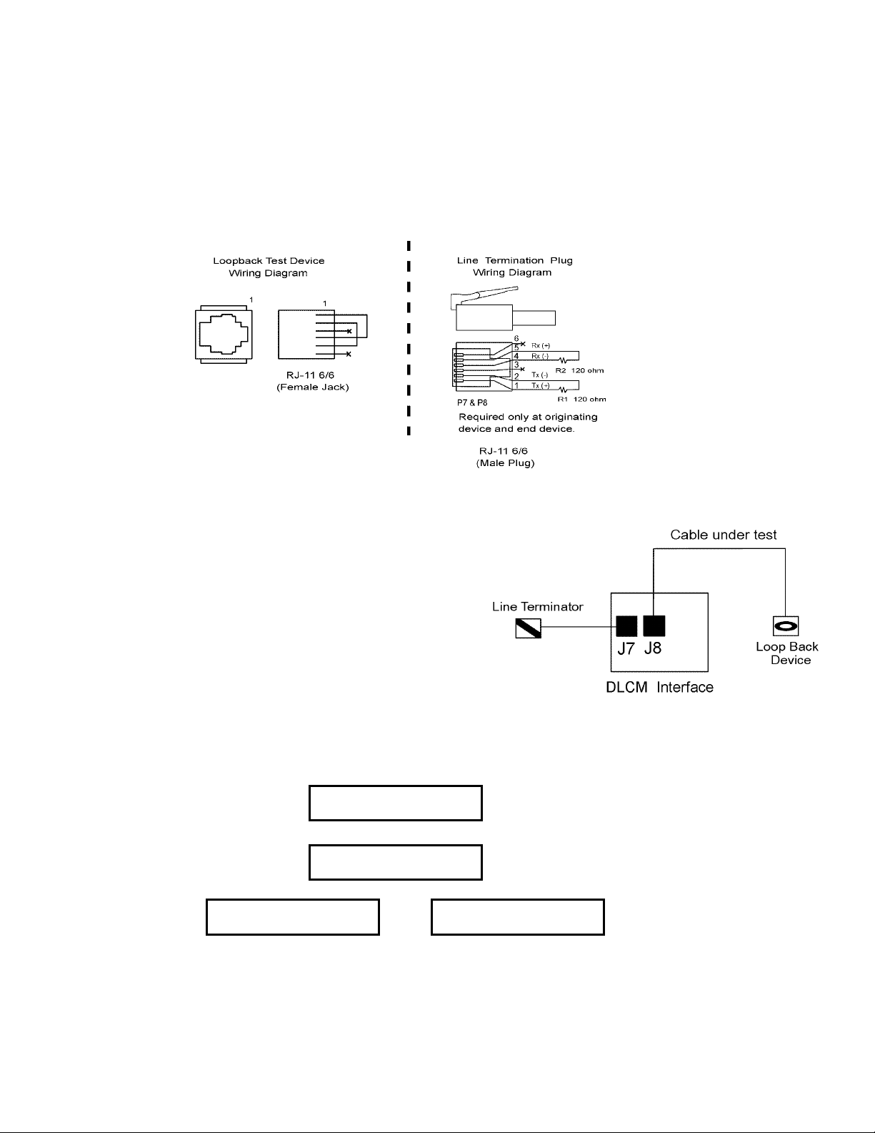
7.2.22.1 Loopback Test Procedure
The Loopback test is helpful in the identification of wiring errors. While this menu is displayed the
DLCM transmits and expects to receive characters back. The display shows the percent (%) of
successful characters exchanged.
The Loopback test requires the installation of a Loopback device at the end of the cable segment under
test. This can be constructed according to Figure 20 below:
Figure 20 – Loopback Device Wiring Diagram
– – Loopback Test Procedure – –
a) Install the line terminator in one port of the
DLCM. (J7 or J8)
b) Install the cable under test in the second port.
(J7 or J8)
c) Install the loop back device at the far end of the
cable under test.
d) With the {LOOPBACK TEST YES} screen displayed, press [ENTER].
LOOPBACK TEST
YES
e) While the LOOPBACK test is being conducted, the following screen is displayed:
PLEASE WAIT
TEST IN PROGRESS
When the test is completed, a result screen is displayed:
100.0% SUCCESS
RETRY YES
- or -
f) If the indicated percent of success is 0%, the cable segment is bad. If the indicated percent of
success is 100%, the segment is good. If the success rate is less than 100%, but greater than zero
you may want to lower the baud rate on the network.
6. To exit the diagnostic menu press [UP] and then press [ENTER]. The {–MENU– / SERIAL COMM}
screen is displayed.
100.0% SUCCESS
RETRY NO
78
Page 85
7.2.23 Language
All displayed text can be displayed in English, Spanish, French or German.
Language Set Up Procedure
1. Press [MENU]. Press [UP] or [DOWN] until {–MENU– / LANGUAGE} is displayed.
LANGUAGE
Press [ENTER] to continue through the language sub-menu.
2. The language type appears on the display. Press [UP] to scroll through the available languages.
LANGUAGE TYPE
ENGLISH
LANGUAGE TYPE
DEUTSCH
When the correct language is displayed, press [ENTER] to activate. All text will be displayed in the
selected language.
3. The display returns to {–MENU– / LANGUAGE}.
7.2.24 Factory Default Settings
All of the DLCM settings can be returned to factory defaults.
Procedure for resetting the factory defaults
1. Press [MENU] and [UP] or [DOWN] until the {–MENU– / FACTORY DEFAULTS} screen is
displayed.
FACTORY DEFAULTS
Press [ENTER] to continue through the factory defaults sub-menu.
2. The display prompts you to not reset all the settings to the factory defaults.
FACTORY RESET?
If a Factory Reset is not desired, press [ENTER] to go back to the {–MENU– / FACTORY
DEFAULTS} screen.
3. If the DLCM is to be reset to the factory defaults, press [UP] to scroll the value to {YES}.
FACTORY RESET?
-MENU-
Press
[UP]
Press
[UP]
-MENU-
NO
YES
LANGUAGE TYPE
FRANCAIS
LANGUAGE TYPE
ESPANOL
Press
[UP]
Press [ENTER] to accept your selection.
4. The display prompts you to verify your action.
Re-setting Factory Defaults will destroy all user calibration information.
ARE YOU SURE?
NO
79
Page 86

Press [UP] to change the value to {YES}. Press [ENTER] to accept your selection. The following
message is displayed:
PLEASE WAIT
5. The first screen displayed during the Re-Set procedure prompts you to turn the motor on.
TURN MOTOR ON
TESTING ENCODER
6. Press [MOTOR].
You will hear the pump motor spin up, and the DLCM will perform an Encoder test (displaying the
following message:)
PLEASE WAIT
TESTING ENCODER
When the Encoder test is complete, (usually takes about 2 or 3 seconds) the DLCM performs a Zero
Calibration (displaying the following message:)
PLEASE WAIT
CALIBRATING ZERO
When the Zero Calibration is complete, you are returned to the {–MENU– / FACTORY DEFAULTS}
screen.
Press [MENU] and the next screen displayed is:
MOTOR STOPPED
Re-establish any Menu and Calibration settings that are non-standard at this time..
7.3 Units
By pressing [UNITS] with the motor on, the display will scroll through the CMH, GPH, LPH, CCH,
CMM, GPM, LPM, CCM, % flow, % stroke length or % motor speed. The DLCM will automatically
convert the motor and stroke settings based on the calibrated flow, to the above referenced units.
The accuracy of the flow rate display is dependent on the pump flow calibration accuracy.
80
Page 87
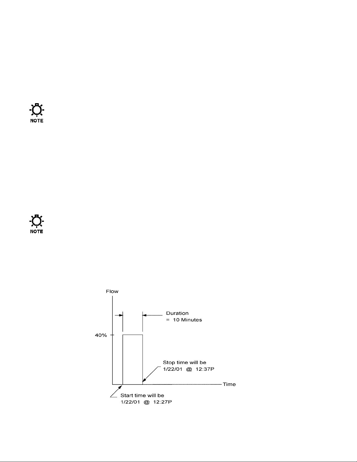
7.4 Varying the Flow Rate - Manually
When the DLCM is in Manual Mode, pump flow rate can be increased by pressing [UP]. The flow rate is
decreased by pressing [DOWN]. The DLCM will display the corresponding value of the flow
adjustment.
If you attempt to adjust the DLCM’s hand-wheel while it is under power, the DLCM will re-adjust back
to the position specified by its programming. The hand-wheel is for emergency manual override only.
Refer to Section 12.1.
Do not adjust the DLCM's hand-wheel while the power is off. This will cause the DLCM to lose its
zero point and force a {ZERO CALIBRATION } at startup.
7.5 Mode
Pressing [MODE], switches the DLCM’s operating mode. If the ANALOG MODE is set to ACTIVE,
then pressing [MODE] will switch between {MANUAL MODE} and {ANALOG MODE}. When
MODBUS MODE is set to ACTIVE, pressing [MODE] will switch between {MANUAL MODE} and
{MODBUS MODE} In essence, this key acts like a local auto/manual switch.
7.6 Batch
The DLCM is capable of following up to three (3) different batch programs. The batches operate in two
modes: One Time Only and Repeating.
When Daylight Savings is set to Auto Change, use caution when setting up batches that run through
or start or stop in the time change over periods where one full hour either doesn’t exist at all or
occurs twice consecutively. If you are in doubt, set the {DAYLIGHT SAVINGS} option to [NO].
(Refer to Section 7.2.3 – Set Time & Date)
7.6.1 One Time Only
The One Time Only batch will start at a specified time and run for a specified duration at a specified
flow rate that you define (refer to Figure 21).
Figure 21 – One Time Only Batch.
81
Page 88
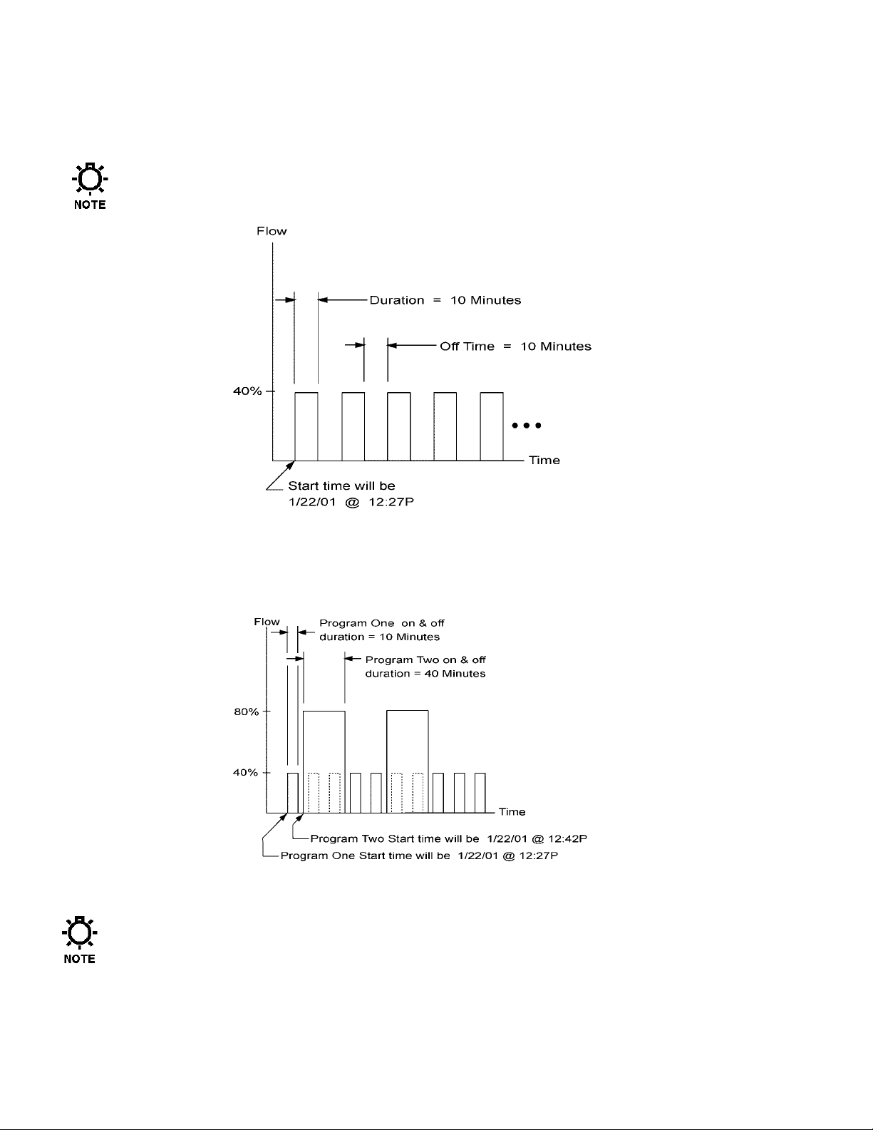
7.6.2 Repeating
A Repeating Batch will start at a specified time and run for a specified duration. It will stop for a
specified period of time and then repeat the run time. This will continue indefinitely (refer to
Figure 22).
Any of the three batches can be specified as one time only or repeating.
Figure 22. Repeating Batch.
7.6.3 Overlapped
The batches can also be overlapped (refer to Figure 23 below).
Figure 23 – Overlapping Batch.
When the batches are overlapped, the flow rates are NOT additive. The highest of the two or three
flow rates is used.
The DLCM can make a 1% per second adjustment of pump stroke length. Remember that when a
batch starts, the DLCM will require some amount of time to achieve the new stroke setting. The
adjustment time is taken as a portion of the batch running time. This will cause the output of the
pump to be skewed.
82
Page 89

Batching system Set Up procedure:
1. Press [BATCH], to enter the batch set-up menu.
2. The display will come up as {BATCHES / ACTIVE} or {BATCHES / INACTIVE}. Press [UP] to
change the batch system to {ACTIVE}.
Setting the batch system to ACTIVE will cause any pre-configured batches that are scheduled to start
at this time, to start immediately, so you might want to do this last.
BATCHES
ACTIVE
Press
[UP]
BATCHES
INACTIVE
Press [ENTER] to continue on to the batch sub-menu.
3. The display shows {EDIT / BATCH #1}. Press [UP] to {EDIT / BATCH #2} and [UP] again to
{EDIT / BATCH #3}.
EDIT
BATCH #1
Press
[UP]
EDIT
BATCH #2
Press
[UP]
EDIT
BATCH #3
The DLCM is supplied with three user programmable batches. Press [ENTER] to select the desired
batch to edit.
4. The display shows {BATCH #1 RATE / 92.5%} (the value and unit of flow will depend on previous
programming). The {RATE} text will be flashing. You can press [UP] or [DOWN] to view/change
the other menu items related to this batch (e.g., RATE / DURATION / TYPE / START, etc.). Pressing
[ENTER] causes the {RATE} value to stop flashing and allows you to program the batch flow rate.
Press [UP] or [DOWN] to set the value.
If a value has been set previously it will be used as a starting point for the new setting.
You can change the display units at any time by pressing [UNITS].
BATCH #1 RATE
92.5%
Press [ENTER] to accept your setting.
5. The display shows {BATCH #1 DURATION / XX HRS, XX MIN} with the word DURATION
flashing. Press [ENTER] to set the duration (i.e., pump on time) of the batch.
BATCH #1 DURATION
12 HRS 30 MIN
6. The hours value should now be flashing on the display. A line (cursor) under the second digit indicates
the field to be changed. Press [UP] or [DOWN] to scroll through the numbers 0-99. Press [ENTER] to
accept the desired hour setting.
BATCH #1 DURATION
12 HRS 30 MIN
83
Page 90

7.
The cursor then moves to minutes field. Use [UP] or [DOWN] to scroll through the numbers 0-5. Set
the first digit of the minute value one position at a time and press [ENTER] to accept it.
BATCH #1 DURATION
12 HRS 30 MIN
8. The cursor then moves to the second digit of the minutes field. Use [UP] or [DOWN] to scroll through
the numbers 0-9. Set the second digit of the minute value. Press [ENTER] to accept the desired
second digit of the minute setting which completes the batch duration entry and exits the Batch
duration screen.
BATCH #1 DURATION
12 HRS 30 MIN
9. The display shows {BATCH #1 TYPE / ONE TIME ONLY}. Press [ENTER] to program the type of
batch.
BATCH #1 TYPE
ONE TIME ONLY
10. You can select from one of two types of batches: either a one time only batch or a repeating batch. A
one time only batch executes the batch only once. A repeating batch repeats an on/off cycle
indefinitely. Press [UP] to scroll between the different batch types.
BATCH #1 TYPE
ONE TIME ONLY
Press
[UP]
BATCH #1 TYPE
REPEATING
Press [ENTER] to select the type of batch desired. If you select {ONE TIME ONLY} skip to step 12.
11. If a Repeating batch is selected, the display prompts you to enter the off duration time of the batch.
BATCH #1 OFF TIME
10 HRS 23 MIN
Follow the procedure outlined in steps 5 through 8. Press [ENTER] to accept the time setting.
12. The display shows {BATCH #1 START TIME / XX:XX XX/XX/XX}. Press [ENTER] to edit the
batch start time. Press [UP] or [DOWN] to set the time and date value one character at a time. Press
[ENTER] to accept your setting.
BATCH #1 START
8:01a 2/3/01
13. The display shows {BATCH #1 CONFIRM? / YES}. Press [ENTER] to confirm the batch or press
[UP] to scroll to the {NO} value and then press [ENTER] to disregard the changes to the batch.
BATCH #1 CONFIRM?
YES
14. If the batch was made active, the display changes to let you know the batch is now pending and
displays the time and date the batch will begin.
BATCH #1 PENDING
8:01a 2/3/01
15. When the clock reaches the start time and date for the batch, the display automatically changes to
indicate that the batch is running. The pump will then operate at the specified rate, for the specified
time.
You can press [UNITS] to change the displayed units while the batch is running.
BATCH #1 RUNNING
92.5%
While a batch is running you can display the time left in HH:MM:SS format by pressing either [UP],
[DOWN] or [ENTER].
BATCH #1 RUNNING
REMAIN 11:59:58
84
Page 91

16.
When the batch has operated for the specified time period, it will automatically shut off the pump's
motor.
17. If this a One Time Only batch, the display will show the batch completed message and the operating
mode will be set to manual.
BATCH #1 COMPLETED
Press any key to clear the display.
18. If this was a repeating batch, the display will return to {BATCH #X PENDING / HH:MM
MM/DD/YY} and the DLCM will wait until its internal clock matches the displayed Time/Date. At
that time, the batch will recycle.
BATCH #1 PENDING
6:54a 2/4/01
7.6.3.1 Inactivating The Batches
If the batch operation is not required to operate over a certain period of time, for instance the
weekend, the batches should be inactivated.
PRESS ANY KEY
MOTOR OFF
Batch Inactivation
1. Press [BATCH]. The screen will show the batch status: {BATCHES / ACTIVE}. Press [UP] to
change the display to {BATCH / INACTIVE}. Press [BATCH] to accept and inactivate the batches
and return to Manual Mode.
85
Page 92

8. Diagrams: Installation / Component
DIAGRAM 1 – DLCM Wiring Diagram
86
Page 93

Diagram 2 – Serial Communications – RS 485 Connections
87
Page 94

9. Specifications
9.1 Overview
The DLCM controller for Pulsar Pumps is an upgrade from the DLC stroke length controller, which
provides all of the same functions, but adds the capability of motor speed control using SCR control of
the armature voltage applied to a permanent magnet DC motor.
S
TROKE LENGTH CONTROL
:
Motor Speed Control:
Combined Calibrated Flow:
Pump Accuracy:
Diaphragm
Steady State
Repeatability
Linearity
±0.5% ±0.5% ±0.5%
±0.5% ±1.0% ±1.0%
±1.0% ±3.0% ±3.0%
Adjustment Response:
Temperature:
0-100% control range. (Software programmable, 0% – 100% factory default)
0.1% resolution
10:1 turndown for accuracy specification.
5-100% control range. (Software programmable, 10% – 100% factory default)
0.1% resolution
20:1 turndown for accuracy specification.
50:1 total turndown for accuracy specification.
6 significant digits for displayed units of flow.
Diaphragm
With Leak
Detection
1% per second on stroke length.
1% per second on steady state speed.
–18°C to 40°C (0°F to 104°F) Operation.
–18°C to 60°C (0°F to 140°F) Storage.
Single Solid
Teflon
Diaphragm
Capacity
Reference
Set Point 10:1 20:1 50:1
Full Rating 10:1 20:1 50:1
Full Rating 10:1 20:1 50:1
Stroke
Length
Turndown RangeAccuracy Standard
Motor
Speed
Combined
Turndown
Low Voltage Inputs
Inputs Field Wiring
Analog Input Channel 1
Analog Input Channel 2
Location
J4 Pin 1 is +
J4 Pin 2 is –
J4 Pin 7 is +
J4 Pin 8 is –
Specification / Description
Any signal within the range of 0 to 25mA (e.g.: 4-20)
or 0 to 5 volts (e.g.: 1-5)
Minimum span of 2mA or 0.4 volts.
Note: No jumpers used. Displayed in mA.
Split Ranging, Reverse Acting and Ratio Control
standard on all units; accessible via calibration.
Fused at 50mA. Protected against mis-wiring.
Surge Protection: 7.4 Joules
Isolation: 500 volts from all other inputs, outputs, and ground.
Specifications same as Channel 1.
88
Page 95

Low Voltage Inputs (cont)
Inputs Field Wiring
PULSAlarm
(Leak Detection)
Digital Input
Programmable as
Level Input
Or
Remote Run / Stop
Low Voltage Outputs
Outputs Field Wiring
Analog Output Channel
Programmable
to output either
Calibrated stroke
length, percent speed,
Or
Calibrated flow
Alarm Status
Digital Output
Programmable as
Remote Run Status
Or
Stroke Counter
Or
Mode Indication
Location
J4 Pin 3 is +
J4 Pin 4 is –
J4 Pin 5 is +
J4 Pin 6 is –
Location
J5 Pin 1 is +
J5 Pin 2 is –
J5 Pin 3 is +
J5 Pin 4 is –
J5 Pin 5 is +
J5 Pin 6 is –
Specification / Description
Dry Contact. (Optically Isolated) – Do not apply powered signal.
Isolation: Not isolated from Digital Input or Motor Thermostat, 500 volts
from all other inputs, outputs and ground
May be software configured as Normally Open or Normally Closed.
May be software configured to operate the Alarm Relay.
May be configured to turn the Pump Motor off.
Dry Contact. (Optically Isolated) – Do not apply powered signal.
Isolation: Not isolated from PULSAlarm or Motor Thermostat, 500 volts
from all other inputs, outputs and ground.
May be software configured as Normally Open or Normally Closed.
May be software configured to operate the Alarm Relay (Level Input
Only).
May be configured to turn the Pump Motor off. (Level Input Only)
Specification / Description
Any signal within the range of 0 – 20mA (e.g.: 4-20).
Minimum span of 2mA.
Maximum load: 700 ohms.
Reverse Acting standard on all units, which is accessible via calibration.
Fused at 50mA protected against mis-wiring.
Surge Protection: 7.4 Joules
Isolation: 500 volts from all inputs and outputs.
Dry Contact (Transistor Type)
VCE (SAT): 0.3 volts
Max forward current: 50mA
Maximum 32VDC
On-state resistance: 100 ohms
Isolation: 5000 volts from all inputs, outputs and ground.
Follows the state of High Voltage Alarm Output, which may be software
configured as Normally Open or Normally Closed.
Dry Contact (Transistor Type)
VCE (SAT): 0.3 volts
Max forward current: 50mA
Maximum 32VDC
On-state resistance: 100 ohms
Isolation: 5000 volts from all inputs, outputs and ground.
May be software configured as Normally Open or Normally Closed.
(Remote Run Status and Mode Indication only).
.
89
Page 96
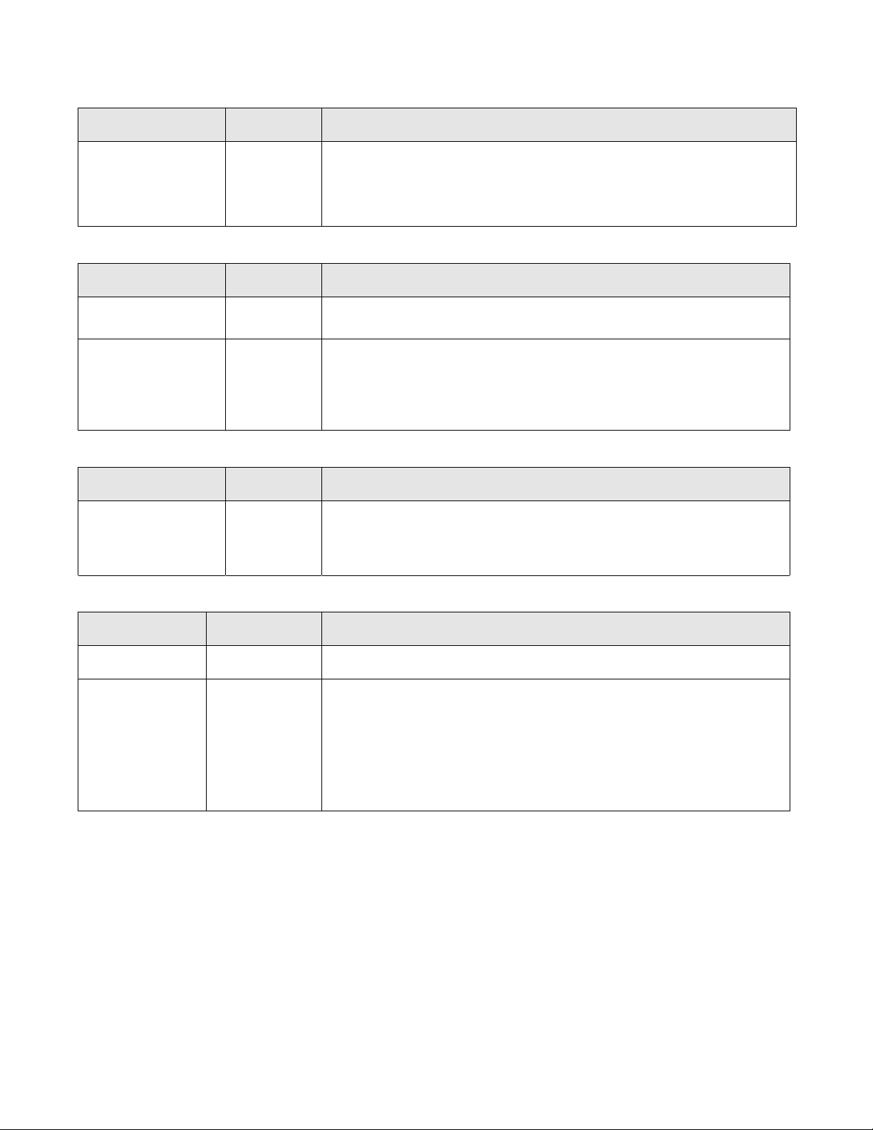
High Voltage Inputs
Inputs Field Wiring
Line Power:
High Voltage Outputs
Inputs Field Wiring
Alarm Relay
Pump Motor
Serial Communications
Inputs Field Wiring
RS–485
Specification / Description
Location
J1 Factory configured to one of the following:
115VAC ±10%, 50/60 Hz, 10 Amp max (with 90 volt armature motors only)
230VAC ±10%, 50/60 Hz, 5 Amp max (with 180 volt armature motors only)
Surge Protection: 7.4 Joules
Software protected against Over/Under voltage. (user selectable)
Specification / Description
Location
J2 Fused at 1 amp at rated Line voltage.
May be software configured as Normally Open or Normally Closed.
J3 Permanent Magnet SCR Drive DC Motors with thermostat.
Base Speed: 1750 RPM, NEMA 56C Frame, Class F or better insulation.
90 Volt armature, 5.0 amps max. at 115 VAC Input Power.
180 Volt armature, 5.0 amps max at 230 VAC Input Power.
Recommended Manufacturer: Baldor Electric Company.
Specification / Description
Location
J7 & J8 Max Cable length: 1219 meters (4000 feet)
Max Address sites: 32
Control Inputs
Control Inputs Field Wiring
Location
Tachometer
Sensor
Motor
Thermostat
J10 Pin 1 is VDC
J10 Pin 2 is Tach
J10 Pin 3 is +
J10 Pin 4 is –
Use 120 ohm terminating resistors at both ends of network.
Isolation: 500 volts from ground and all other inputs and outputs.
Specification / Description
Connection point for TURCK Sensor.
Used for sensing Motor Speed.
Dry Contact (Optically Isolated) – Do not apply powered signal.
Isolation: Not isolated from PULSAlarm or Digital Input, 500 volts from all
other inputs, outputs, and ground.
May be software configured as Normally Open or Normally Closed (default).
May be software configured to operate the Alarm Relay (default is YES).
May be software configured to turn the Pump Motor OFF (default).
If MOTOR OFF is selected may optionally restart the Pump Motor when the
thermostat resets (default).
90
Page 97

10. Factory Default Values
CALIBRATION
Pump Flow 1-Point Calibration on PULSAR at Rated Flow and Pressure.
Analog Input 4.0 - 20.0mA @ 100% Ratio
Analog Output 4.0 - 20.0mA @ 100% Ratio
DIAGNOSTICS
Alarms Cleared
DATE/TIME
Date Format MM/DD/YY
Time Format 24:00
Daylight Savings Time No
ANALOG INPUT
Failure Mode channel #n Freeze at last signal / Restore to Analog Mode/ Error message enabled
Sample Average channel #n 20 Samples
Sample Update channel #n 20 Samples (5.0 Seconds)
ANALOG OUTPUT
Stroke and Speed setting Calibrated Stroke and Speed combined
END POINT & PRIORITY
Stroke Minimum 0%
Stroke Maximum 100%
Speed Minimum 10%
Speed Maximum 100%
Priority Speed
LEAK DETECTION
Failure Mode Inactive
LEVEL INPUT
Failure Mode Inactive
DIGITAL OUTPUT
Run/Stop Normally Open
MOTOR THERMOSTAT
Input Enabled
Switch Normally Closed
Motor Off
Alarm
Restore to:
OVER TEMPERATURE
Error Message Enabled
POWER FAILURE
Failure Mode During power up – Motor Off
Wrong Voltage Hard Shutdown
ALARM RELAY
Relay Output Normally Open
SECURITY
Enabled – Number of input channels enabled is one.
On
Motor On
Remains as previously set
91
Page 98

NUMBER FORMAT
Separators X , XXX . XX (Comma / Decimal)
Position PULSAR dependent (e.g., 9.99999, 0.999999, etc.)
Factory set to match pumphead size. Refer to Factory
Decimal Position Settings below.
CONTRAST
Restored to initial Factory setting
SERIAL COMM
Net Address Disabled
LANGUAGE
English
MODE
UNITS
BATCH
Manual – Motor Off
Percent (%)
Inactive
Batch #n Rate 0%
Batch #n Duration 0 H 00 M
Batch #n Type One Time Only
Batch #n Start Current Date and Time for first setting
FLOW RATE
0%
Stroke Position 0%
Motor Speed 10%
FACTORY DECIMAL POSITION SETTINGS
RATED CAPACITY RANGE UNITS –MENU – / DECIMAL POSITION
5.99999 to 59.9999 CMH 999.999
1,585.03 to 15,850.3 GPH 999.999
5,999.99 to 59,999.9 LPH 999.999
5,999,990 to 59,999,900 CCH 999.999
0.0999999 to 0.999999 CMM 999.999
26.4172 to 264.172 GPM 999.999
99.9999 to 999.999 LPM 999.999
99,999.9 to 999,999 CCM 999.999
0.599999 to 5.99999 CMH 99.9999
158.503 to 1,585.03 GPH 99.9999
599.999 to 5,999.99 LPH 99.9999
599,999 to 5,999,990 CCH 99.9999
0.00999999 to 0.0999999 CMM 99.9999
2.64172 to 26.4172 GPM 99.9999
9.99999 to 99.9999 LPM 99.9999
9,999.99 to 99,999.9 CCM 99.9999
0.0599999 to 0.599999 CMH 9.99999 (default size)
15.8503 to 158.503 GPH 9.99999 (default size)
59.9999 to 599.999 LPH 9.99999 (default size)
59,999.9 to 599,999 CCH 9.99999 (default size)
0.000999999 to 0.00999999 CMM 9.99999 (default size)
0.264172 to 2.64172 GPM 9.99999 (default size)
0.999999 to 9.99999 LPM 9.99999 (default size)
999.999 to 9,999.99 CCM 9.99999 (default size)
Actual Flow is usually
slightly larger than the
rated flow.
92
Page 99

FACTORY DECIMAL POSITION SETTINGS (cont.)
RATED CAPACITY RANGE UNITS –MENU – / DECIMAL POSITION
0.00599999 to 0.0599999 CMH 0.999999
1.58503 to 15.8503 GPH 0.999999
5.99999 to 59.9999 LPH 0.999999
5,999.99 to 59,999.9 CCH 0.999999
0.0000999999 to 0.000999999 CMM 0.999999
0.0264172 to 0.264172 GPM 0.999999
0.0999999 to 0.999999 LPM 0.999999
99.9999 to 999.999 CCM 0.999999
0.000000001 to 0.00599999 CMH 0.0999999
0.000001 to 1.58503 GPH 0.0999999
0.000001 to 5.99999 LPH 0.0999999
0.001 to 5,999.99 CCH 0.0999999
0.00000000001 to 0.0000999999 CMM 0.0999999
0.00000001 to 0.0264172 GPM 0.0999999
0.00000001 to 0.0999999 LPM 0.0999999
0.00001 to 99.9999 CCM 0.0999999
93
Page 100

11. Trouble Shooting Guide
11.1 System Diagnostics
Your DLCM contains extensive diagnostics that allow it to determine the source of common problems. If
your DLCM is not operating properly, your first course of action should be to review the
{DIAGNOSTICS} sub-menu. To access this menu from the standard operating mode follow this
procedure (provided your user interface – keypad and display – is functioning):
1. Press [MOTOR] repeatedly until the display reads {MOTOR OFF}.
2. Cycle power to the DLCM (turn the main OFF then ON). This will cause the self-test routine to re-
execute.
3. Press [MENU]. The screen {–MENU– / DIAGNOSTICS-1} is displayed. The value, in this case
'1' indicates how many failures were detected.
4. Press [ENTER] to enter the Diagnostics Menu. The screen {DIAG MENU 1/11 / POWER IN:
OK} is displayed.
5. Repeatedly press [UP] to cycle through all nine Diagnostic screens.
6. If a screen displays a FAIL message, press [ENTER] to display the time and date the failure
occurred. Press [ENTER] again to display the clear screen. Press [UP] and then [ENTER] to clear
the message. (This paragraph does not apply should you encounter a Battery Fail or Circuit Fail
situation).
Make a note of any failures reported in the Diagnostics Menu. Using this information, proceed with
the troubleshooting instructions below:
Other actions may be necessary to bring the process back to normal conditions before clearing a
failure.
MENU (DIAGNOSTICS)
Symptom Probable Cause Possible Solution
DIAG 1/11
POWER IN:
FAIL
DIAG 2/11
ANALOG IN:
FAIL
DIAG 3/11
MODBUS
FAIL
DIAG 4/11
LEAK DET:
FAIL
DIAG 5/11
LEVEL
INPUT: FAIL
DIAG 6/11
MOTOR TEMP
The power to the DLCM failed while the
pump motor was running.
The Analog Input signal fell under the
calibrated range, or fell to 0 within 0.25
seconds (i.e., the signal was changing by
more than 8.8mA per second and was less
than 0.3mA).
A properly formatted and addressed
MODBUS message was not received in the
allotted time.
The Leak Detection Switch closure activated
according to its configuration.
The Level Input Switch closure activated
according to its configuration.
The motor exceeded its maximum internal
temperature.
Place DLCM in {MOTOR OFF} operating
mode before disconnecting power. Refer to
POWER trouble shooting.
Place DLCM in {MANUAL MODE} or
OFF before the signal loss occurs. Recalibrate Analog Input. Condition Analog
Input Signal. Refer to ANALOG INPUT
trouble shooting.
Increase the Response Time setting.
Review Section 7-General Operation: Leak
Detection Failure Set-up. Refer to LEAK
DETECTION trouble shooting.
Review Section 7-General Operation:
Level Input Failure Set-up. Refer to
LEVEL INPUT trouble shooting.
Relocate to a cooler area. Increase
minimum motor speed setting.
94
 Loading...