

Page 1

DIGITAL GLYCOL FEEDER
DGF1, DGF2
OPERATING INSTRUCTIONS
P/N: 72-900-24 Rev J
(06-22-07)
Manufactures of Quality Pumps,
Controls and Systems
STANDARD PUMP OPERATION
27101 Airport Road
Punta Gorda, FL 33982
Telephone (941) 575-3800
Fax: (941) 575-4085
(800) 333-6677
www.pulsa.com
Page 2

FACTORY SERVICE POLICY
Your Digital Glycol Feeder (DGF) is designed to make-up lost glycol in a closed loop system. If
you are experiencing a problem with your DGF consult the trouble-shooting guide. If the
problem is not covered or cannot be solved, please contact your local Pulsafeeder Representative
or our Technical Service Department at (800) 333-6677 for further assistance.
Trained individuals are available to diagnose your problem and arrange a solution. Solutions may
include purchasing a replacement unit or returning the DGF to the factory for inspection and
repair. All returns require a Return Material Authorization (R.M.A.) number to be issued by
Pulsafeeder. Pulsafeeder personnel may credit replacements purchased under a possible warranty
situation after an examination of the original parts.
Certain components may be purchased for replacement. Pulsafeeder personnel may credit parts
purchased to correct a warranty issue after examination of the original parts. Parts returned for
warranty consideration that test satisfactorily will be sent back to the originator freight collect.
Any field modifications will void the Pulsafeeder Digital Glycol Feeder warranty. Out-ofwarranty repairs will be subject to Pulsafeeder's standard bench fees and testing costs
associated with replacement components.
WARRANTY
Pulsafeeder Inc. warrants the Digital Glycol Feeder against defects in materials or workmanship
for a period of one year under normal use, from the date of shipment. The manufacturer's liability
is limited to the repair or replacement of any failed component that is proven defective in material
or workmanship upon manufacturer's examination. This warranty does not include removal or
installation costs and in no event shall the manufacturer's liability exceed the selling price of such
equipment.
This warranty does not extend to damage by corrosion, erosion, mishandling, any force of nature
or any other conditions beyond the seller's reasonable control.
The manufacturer disclaims all liability for damage to its products through improper installation,
maintenance, use or attempts to operate such products beyond their functional capacity,
intentionally or otherwise or any unauthorized repair. The manufacturer is not responsible for
consequential or other damages, injuries or expenses incurred through the use of its products.
The above warranty is in lieu of any other guarantee, either expressed or implied. The
manufacturer makes no warranty of fitness or merchantability. No agent of ours is authorized to
make any warranty other than the above.
FCC WARNING
This equipment generates and uses radio frequency energy. If not installed and used properly, in
strict accordance with the manufacturer’s instructions, it may cause interference to radio
communications. Operation of this equipment in a residential area is likely to cause interference
in which case the user, at his own expense, will be required to take whatever measures necessary
to correct the interference.
i
Page 3

Copyright
Copyright ©1999 Pulsafeeder, Inc. All rights reserved.
Information in this document is subject to change without notice. No part of this publication may
be reproduced, stored in a retrieval system or transmitted in any form or any means electronic or
mechanical, including photocopying and recording for any purpose other than the purchaser’s
personal use without the written permission of Pulsafeeder, Inc.
ii
Page 4

Table of Contents
1. INTRODUCTION .....................................................................................................................................1
1.1 Systems and Options..............................................................................................................2
2. I
NSTALLATION ......................................................................................................................................3
2.1 Assembly..................................................................................................................................3
2.1.1 Tools Required For Assembly........................................................................................3
2.1.2 Pre–Assembly..................................................................................................................5
2.1.3 Location............................................................................................................................6
2.1.4 Plumbing...........................................................................................................................6
2.1.5 Mounting The Tank..........................................................................................................7
2.1.6 Mounting The Controller.................................................................................................8
2.1.7 Installing The Level Wand...............................................................................................9
2.1.8 Connecting The Pressure Switch...................................................................................10
2.1.9 Connecting The Pump.....................................................................................................10
2.1.10 Connecting The Re-Circulation Line..............................................................................10
2.2 Electrical Wiring ......................................................................................................................12
2.2.1 115VAC Pre-Wired Unit Connections ............................................................................12
2.2.2 115VAC/230VAC Conduit Connections.........................................................................15
3. G
LYCOL FEEDER SYSTEM.....................................................................................................................23
3.1 User Interface...........................................................................................................................23
3.2 Start Up & Calibration.............................................................................................................24
4. O
PERATION ..........................................................................................................................................28
4.1 Operating Modes.....................................................................................................................28
4.1.1 Normal...............................................................................................................................28
4.1.2 Feeding Glycol.................................................................................................................28
4.1.3 Alarm.................................................................................................................................28
5. S
PECIFICATIONS ...................................................................................................................................29
5.1 Environment.............................................................................................................................29
5.2 Power Requirements...............................................................................................................30
5.3 Inputs........................................................................................................................................30
5.4 Outputs.....................................................................................................................................31
5.4.1 Pump.................................................................................................................................31
5.4.2 Alarm.................................................................................................................................31
5.5 Audible Indicators...................................................................................................................31
6. T
ROUBLE SHOOTING.............................................................................................................................32
7. M
AINTENANCE......................................................................................................................................33
7.1 Cleaning ...................................................................................................................................33
8. P
UMP INFORMATION..............................................................................................................................34
8.1 Drive..........................................................................................................................................34
8.2 Suction Lift...............................................................................................................................34
8.3 Rotation....................................................................................................................................34
N
OTES........................................................................................................................................................37
PPENDIX A – REFERENCE CHARTS............................................................................................................38
A
iii
Page 5
Conventions
For the remainder of this bulletin, the following Conventions are in effect.
A WARNING DEFINES A CONDITION THAT COULD CAUSE DAMAGE TO BOTH THE
EQUIPMENT AND THE PERSONNEL OPERATING IT
WARNING
Notes are general information meant to make operating the equipment easier.
Tips have been included within this bulletin to help the operator run the equipment in
the most efficient manner possible. These “Tips” are drawn from the knowledge and
experience of our staff engineers, and input from the field.
.
. PAY CLOSE ATTENTION TO ANY
This is a procedure heading. A Procedure Heading indicates the starting point for a
procedure within a specific section of this manual.
iv
Page 6
1. Introduction
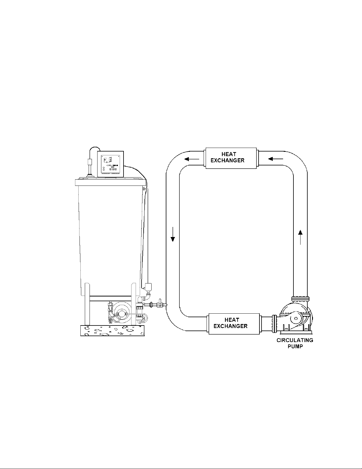
The Digital Glycol Feeder (DGF), is designed to make-up for lost glycol in a closed loop system.
It accomplishes this by monitoring system pressure. When system pressure drops below a set
pressure (indicating glycol loss), the pump activates and restores the lost glycol, bringing the
system pressure back to the proper operating level.
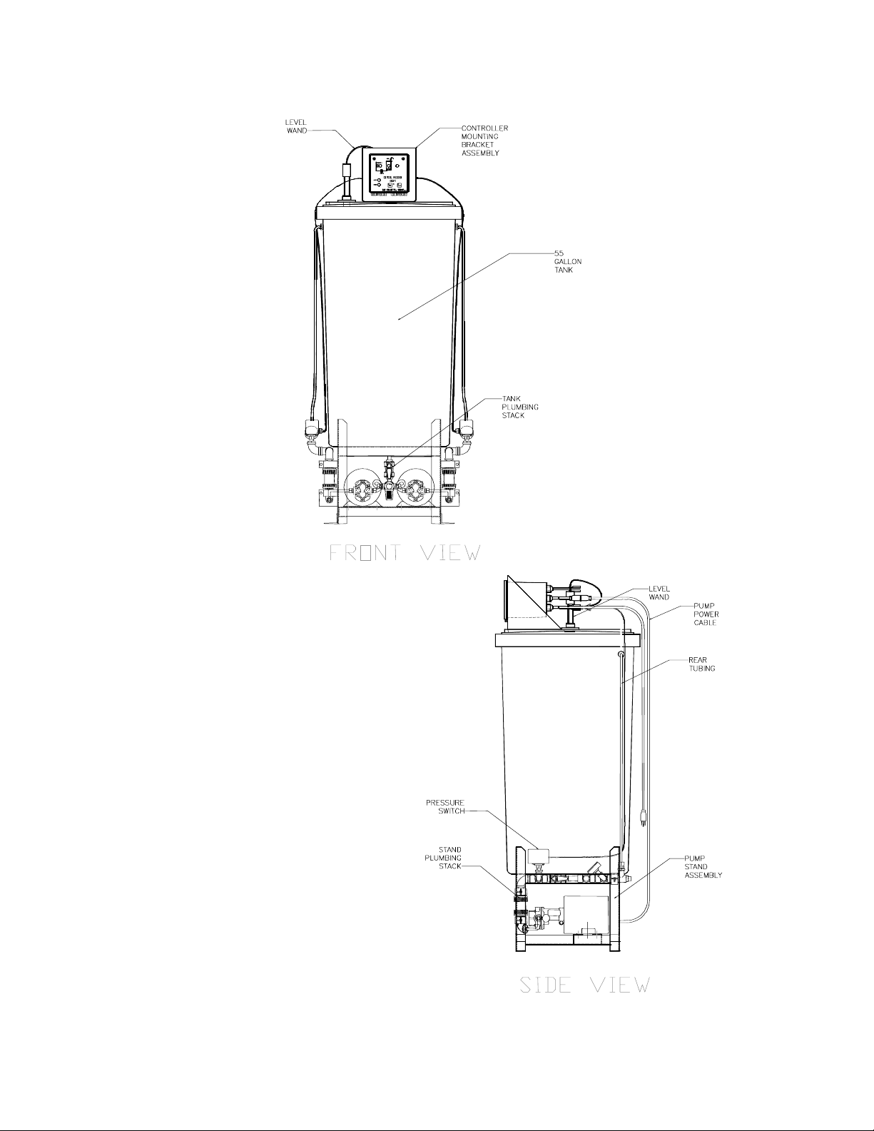
Model DGF1 includes a control unit in a NEMA Type 4 enclosure, a 55 gallon polyethylene tank,
a level wand, a pressure switch and a positive displacement pump for controlling glycol feed in a
single loop system. The feeder is mounted on a welded stand for ease in shipment and
installation.
Model DGF2 controls a dual loop system.
Figure 1 – Typical Installation
1
Page 7
1.1 Systems and Options
The Glycol Feeder for Closed Loop Systems includes:
• control unit in a NEMA type 4X enclosure
• 55 gallon polyethylene tank and stand
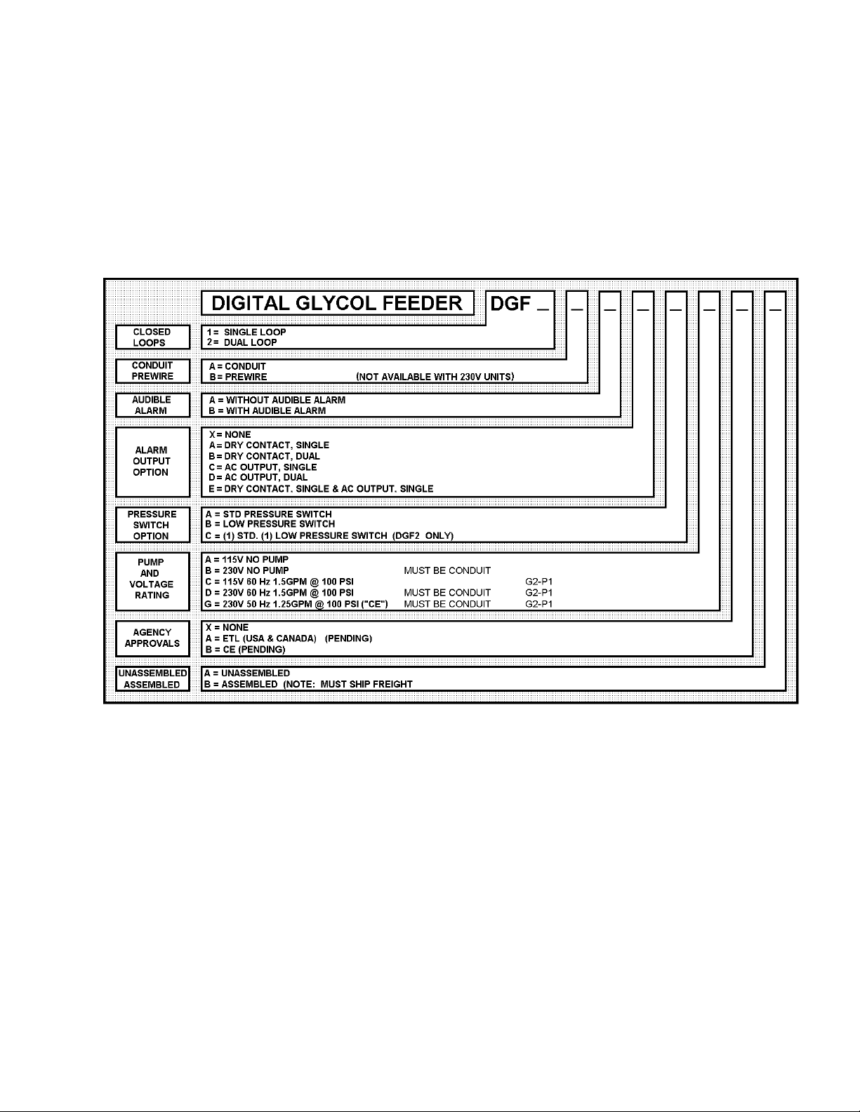
Refer to Figure 2 – Options List, for Glycol Feeder options.
Figure 2 – Options List
2
Page 8
2. Installation
2.1 Assembly
If your DGF is shipped to you unassembled, perform the following: (If you ordered the
assembled version go to section 2.2 – Electrical Wiring.)
FAILURE TO FOLLOW THESE WARNINGS AND ASSEMBLY INSTRUCTIONS COULD RESULT
IN SERIOUS INJURY OR DEATH
• Read all instructions carefully before assembly.
• Check all connections to ensure they are tight before applying pressure to the system.
• Wire in accordance to applicable electrical codes.
• Never subject components to full water immersion.
• Never attempt to move this system when the tank is full.
• DO NOT apply lateral force to the tank. The tank can tip spilling the contents.
• When filling the tank use care to prevent spillage or splashing on the wiring or tank cover.
• This system is designed for feeding Ethylene Glycol into pressurized closed loop systems.
• DO NOT run pumps dry.
• DO NOT exceed rated pressure of 80 psi.
DO NOT DEVIATE FROM THESE ASSEMBLY IN STRUCTIONS. QUALIFIED CUSTOMER
SERVICE REPRESENTATIVES CAN BE REACHED AT THIS TOLL FREE NUMBER IF
ASSISTANCE IS NEEDED
!
: 1 (800) 333-6677.
2.1.1 Tools Required For Assembly
• Phillips head screw driver.
• Adjustable wrench.
3
Page 9
4
Page 10
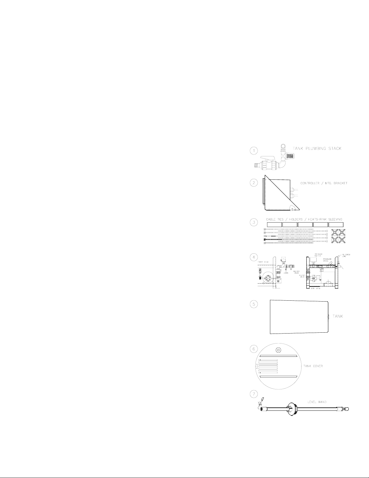
Figure 3 – Glycol Feeder Assembly
2.1.2 Pre–Assembly
1. Unpack all cartons and inspect for damage. If shipping damage is found, save all packaging
and notify the carrier immediately. Lay out and identify all parts.
Item 1: Tank Plumbing Stack.
2: Controller mounted on a bracket with two-cover
Item
mounting screws attached.
Item 3: Package of Cable Ties & Cable Tie Holders.
Parts List:
4: Pump/Stand assembly including stand, pump(s)
Item
with tubing attached to both the suction and discharge sides,
stand plumbing assembly(s), pressure switch cable (attached
to switch) and re- circulation tubing (attached to the pressure
relief valve on the back end of the stand plumbing stack).
Item
5: Tank with plumbing stack adapter attached.
6: Tank cover with two controller mounting screws
Item
attached.
7: Level Wand
Item
5
Page 11
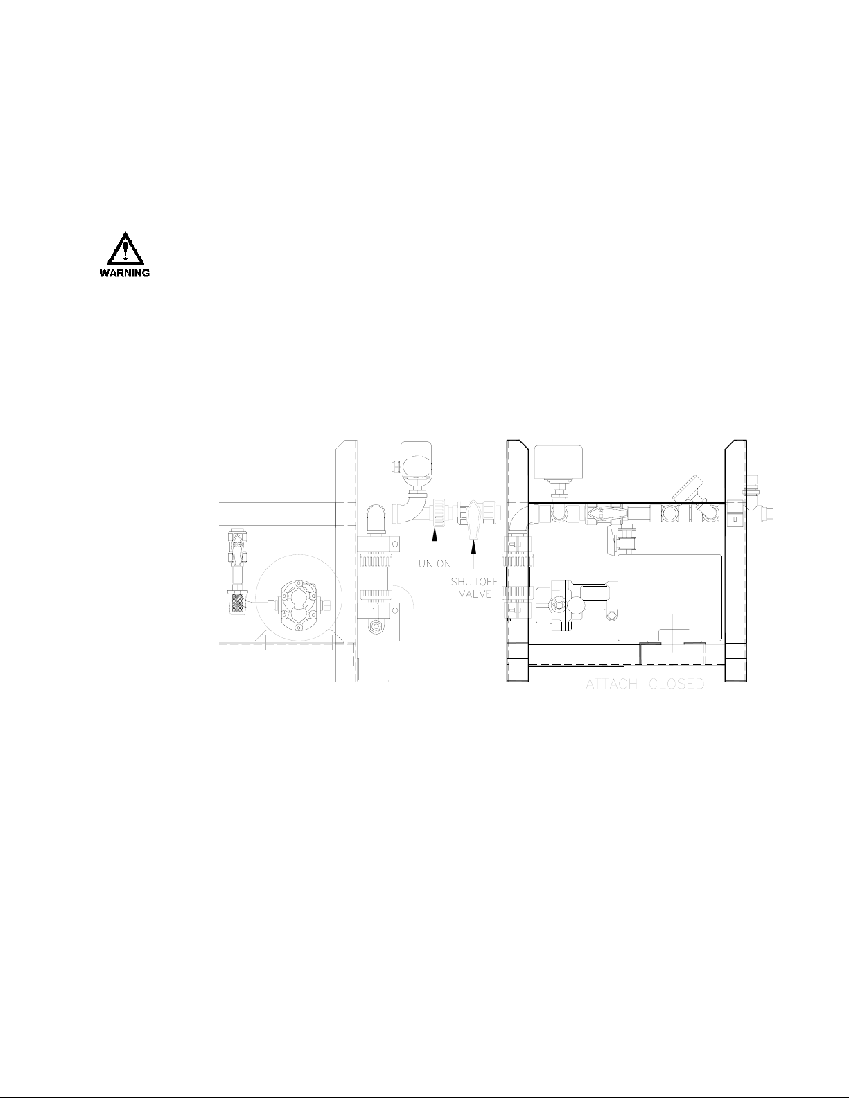
Figure 4 – Parts ListLocation
1. Locate a space approximately 3’ x 3’ that is convenient to system piping and to an electrical
outlet or power source.
2. Place the tank stand in the installation location with the front (pump head/wet end side)
facing out.
THE ASSEMBLY IS VERY HEAVY AND HELP MAY BE REQUIRED. DO NOT LIFT THE
STAND BY THE PLUMBING STACK
STAND ASSEMBLY
. USE GLOVES AS THE STAND MAY HAVE SHARP EDGES.
2.1.3 Plumbing
1. Attach the plumbing stack on the side of the stand to the closed loop system using a union
and shut off valve (not supplied).
(S). LIFT THE UNIT BY THE METAL FRAME OF THE
Figure 5 – Closed Loop Connection
6
Page 12
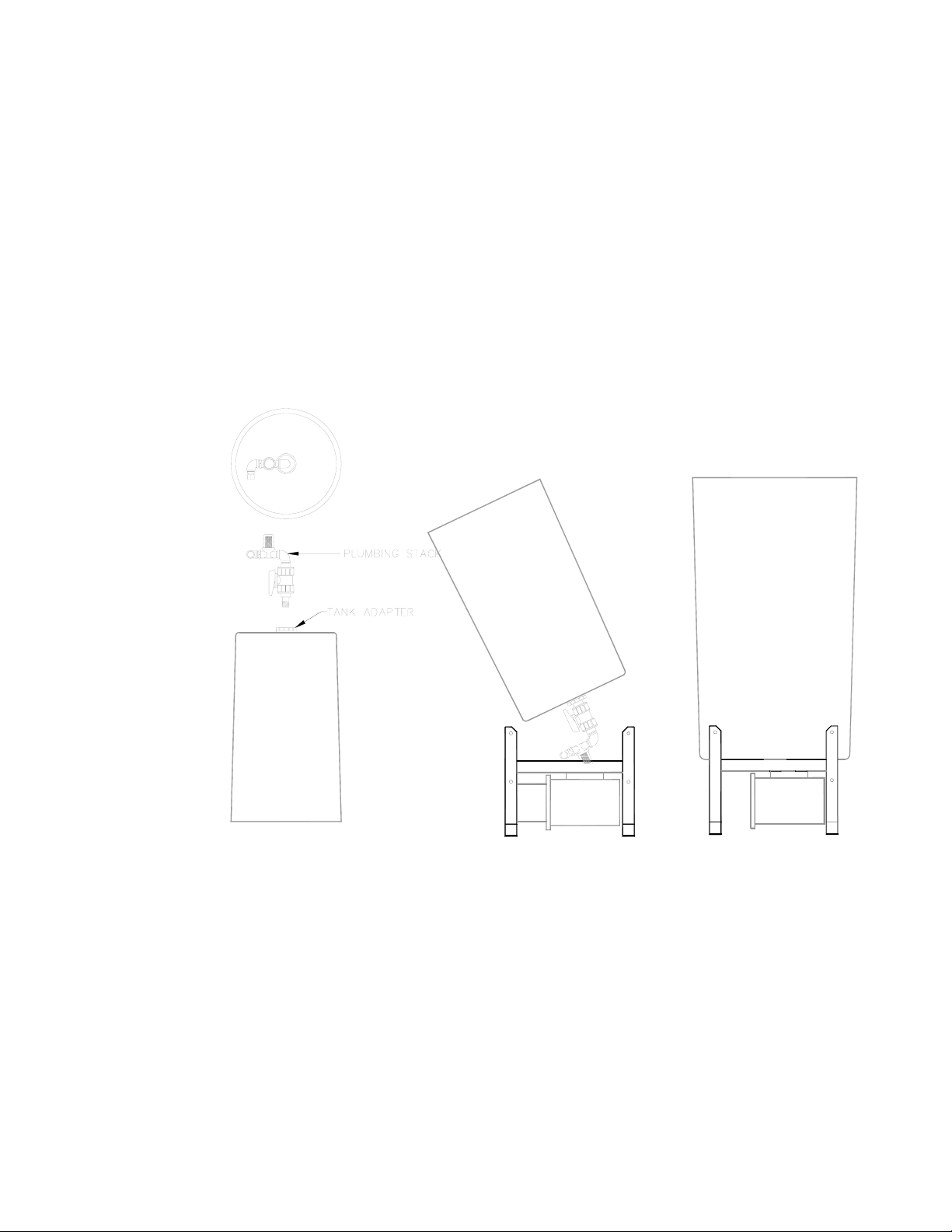
2.1.4 Mounting The Tank
1. Turn the tank upside down and screw the plumbing stack assembly into the adapter attached
to the bottom of the tank. Tighten until snug plus 1/4 turn. Orient as shown in Figure 6 –
Tank Installation below.
2. Lift the tank, turning the open side up with the plumbing stack against your body.
3. Tip the top of the tank toward you and lower the tank onto the stand while feeding the
plumbing stack through the pump support and under the front cross bar between the pumps.
Figure 6 – Tank Installation
2.1.5
7
Page 13
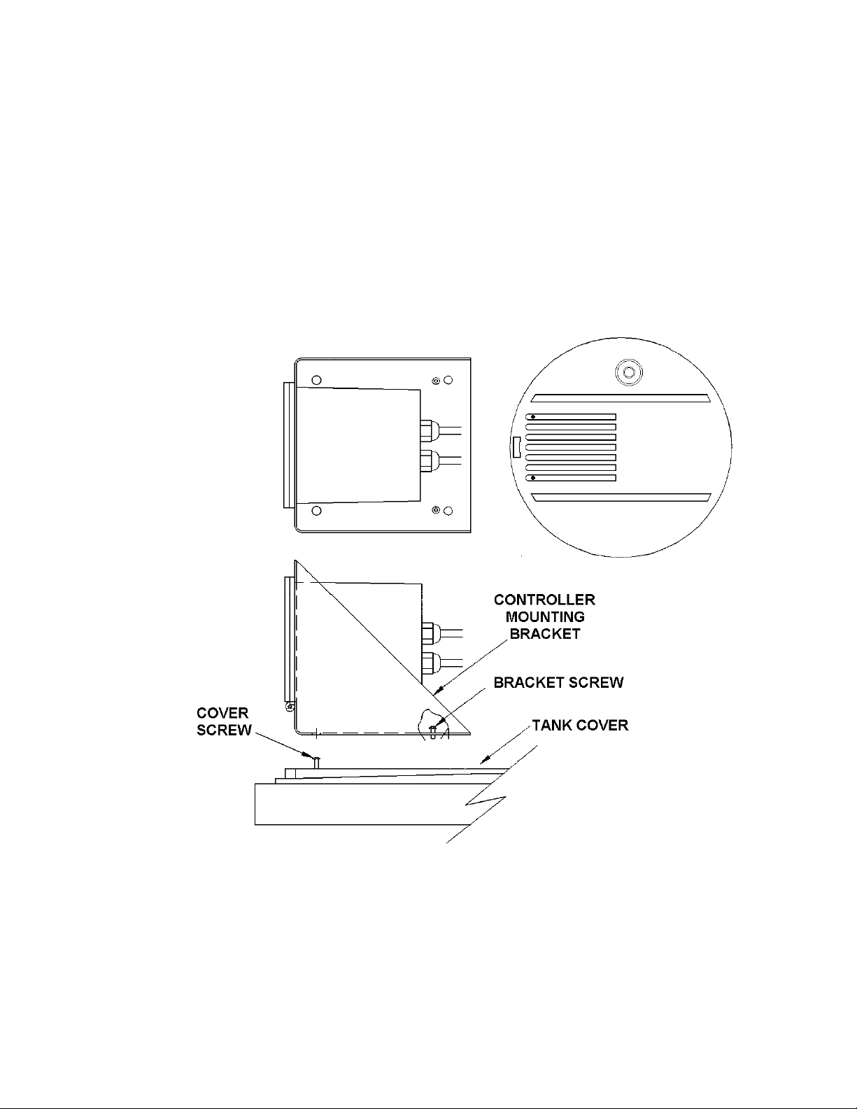
Mounting The Controller
1. Loosen the screws mounted to the back of the controller mounting bracket. DO NOT
REMOVE!
2. Set the controller on the tank cover so that the holes in the front of the controller bracket slide
over the two screws mounted to the top of the tank cover.
3. Slide the bracket assembly towards the front of the unit so that the bracket fits under the
screw head while aligning the rear bracket screws with the pre-drilled holes in the tank cover
and secure the rear screws.
4. Tighten the front screws.
5. Place the tank cover on the top of the tank so the controller is facing the front (wet) end of the
pump(s).
Figure 7 – Controller Installation
8
Page 14
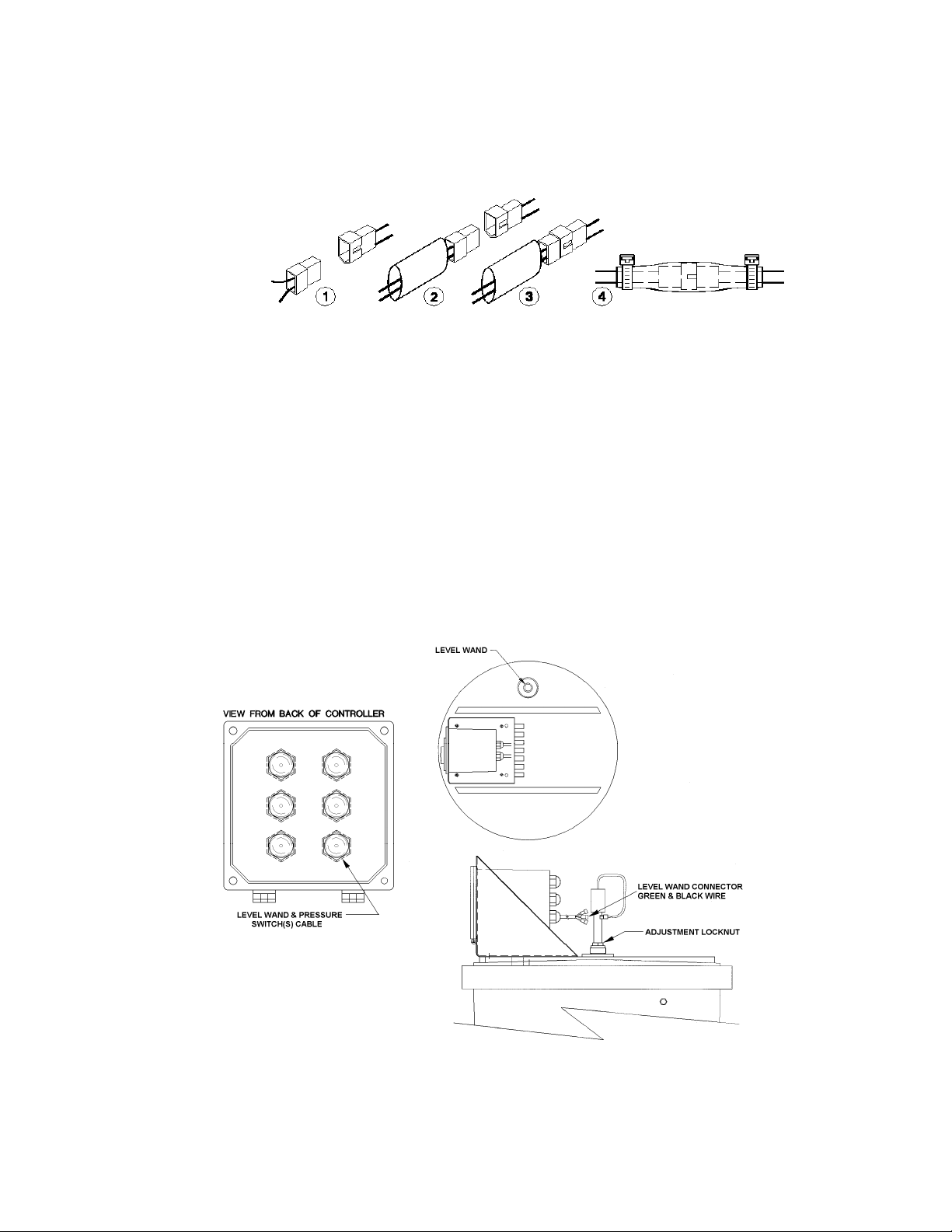
Refer to the Molex/Heat shrink sleeving procedure shown below while making the
connections outlined in sections 2.1.7, and 2.1.8.
1 Find Mating Connections.
2 Slide heat shrink sleeving over one of the connectors.
3 Assemble the connectors together.
4 Slide heat shrink over connection. Shrink sleeving and secure each end with a
cable tie as shown.
2.1.6 Installing The Level Wand
1. Insert the Level Wand in the hole provided in the tank cover.
2. Adjust the height of the wand to the alarm level required by loosening the adjustment lock
nut and sliding the wand through the adapter.
3. Tighten the adjustment lock nut.
4. Connect the level wand cable to the three position cable on the back of the controller, marked
“LEVEL WAND”.
Figure 8 – Level Wand Installation
9
Page 15

2.1.7 Connecting The Pressure Switch
1. Connect the cable from the pressure switch to the three position cable on the back of the
controller marked “PRESSURE SWITCH #1”.
Repeat steps 2.1.8, 2.1.9, and 2.1.10 if you have a dual loop system. The second switch is
connected to the cable marked “PRESSURE SWITCH #2”.
2.1.8 Connecting The Pump
1. Connect the loose end of the tubing attached to the pump to the fitting on the plumbing stack
on the bottom of the tank.
a) Insert the tubing approximately 1/2” into the fitting.
2. Using an adjustable wrench, tighten the fitting until snug. DO NOT over tighten. Fittings
should be hand tight plus 1/4 turn. (If you have a dual pump system, repeat this step for the
second pump.)
2.1.9 Connecting The Re-Circulation Line
1. Connect the loose end of the tubing attached to the pressure relief valve on the back end of
the plumbing stack (attached to the side of the stand) to the fitting on the side of the tank.
a) Insert the tubing approximately 1/2” into the fitting.
2. Using an adjustable wrench, tighten the fitting until snug. DO NOT over tighten. Fittings
should be hand tight plus 1/4 turn. (If you have a dual pump system, repeat this step for the
second pump.)
Refer to Figure 9 – Primary Connections on the next page as you are performing steps 2.1.8,
2.1.9, and 2.1.10.
10
Page 16

Figure 9 – Primary Connections
11
Page 17

2.2 Electrical Wiring
The procedure you will use to make the electrical connections is dependent on the option
package you select (refer to Figure 2 – Options List).
2.2.1 115VAC Pre-Wired Unit Connections
2.2.1.1 Dual AC Alarm Connection
Figure 10 – Dual AC Alarm Connection
1. Plug the 2-wire Molex connector tagged Level Wand into its mate on the end of the PVC
wand (low liquid level switch).
2. Plug the 2-wire Molex connector tagged Pressure Switch #1 into its mate on the pressure
switch attached to the closed loop system.
3. Plug the pump into the Pump #1 Power receptacle (pigtail).
4. Plug the Alarm Indicators (e.g.: warning light) into the associated AC Alarm (#1 & #2)
receptacles (power pigtail).
5. Plug in the Main Power cord.
For the purpose of this manual, the DGF1 is used as the example. If you have a DGF2
repeat steps 2 and 3 for the second pressure switch and pump.
12
Page 18

2.2.1.2 Dual Dry Contact Connection
Figure 11 – Dual Dry Contact Connection
1. Plug the 2-wire Molex connector tagged Level Wand into its mate on the end of the PVC
wand (low liquid level switch).
2. Plug the 2-wire Molex connector tagged Pressure Switch #1 into its mate on the end of the
associated pressure switch attached to the closed loop system.
3. Plug the 2-wire Molex connector tagged Dry Contact #1 into a device capable of receiving a
dry-contact input (e.g., PLC, PULSATROL PLUS LEVEL INPUT, etc.)
4. Plug the 2-wire Molex connector tagged Dry Contact #2 into. a device capable of receiving a
dry-contact input (e.g., PLC, PULSATROL PLUS LEVEL INPUT, etc.)
5. Plug the pump into the Pump #1 Power receptacle (pigtail).
6. Plug in the Main Power cord.
For the purpose of this manual, the DGF1 is used as the example. If you have a DGF2
repeat steps 2 and 5 for the second pressure switch and pump.
13
Page 19

2.2.1.3 Dry Contact – AC Alarm Connection
Figure 12 – Dry Contact – AC Alarm Connection
1. Plug the 2-wire Molex connector tagged Level Wand into its mate on the end of the PVC
wand (low liquid level switch).
2. Plug the 2-wire Molex connector tagged Pressure Switch #1 into its mate on the associated
pressure switch attached to the closed loop system.
3. Plug the 2-wire Molex connector tagged Dry Contact #1 into a device capable of receiving a
dry-contact input (e.g., PLC, PULSATROL PLUS LEVEL INPUT, etc.).
4. Plug the Alarm Indicator (e.g.: warning light) into the associated AC Alarm receptacle
(power pigtail).
5. Plug the pump into the Pump #1 Power receptacle (pigtail).
6. Plug in the Main Power cord.
For the purpose of this manual, the DGF1 is used as the example. If you have a DGF2 there
are connections for the second pressure switch, and pump (steps 2, & 5).
14
Page 20

2.2.2 115VAC/230VAC Conduit Connections
If your application requires 230VAC, or you did not order the 115VAC unit pre-wired, you
will hard wire the electrical connections as shown in the following paragraphs (refer to
Figure 13 – Main Circuit Board below for terminal locations).
2.2.2.1 Getting Around The Main Circuit Board
The Main Circuit board shown below (Figure 13 – Main Circuit Board) has all the possible
connection points shown. Remember that the main circuit board installed in your DGF will
include only the connection points for the options you ordered.
Figure 13 – Main Circuit Board
Complete the electrical wiring of your DGF following the steps defined below, in the order
specified. For a proper setup, do not skip or modify any steps.
Install the unit according to IEC 1010 Clause 6, and to local wiring code(s).
15
Page 21

2.2.2.1.1 DGF Inputs (J14)
The inputs to the DGF are pre-wired at the factory and are connected to main circuit board at
J14, via a pre-wired harness with Molex connectors.
Figure 14 – DGF Inputs
1. Plug the 2-wire Molex connector tagged Level Wand into its mate on the end of the PVC
wand (low liquid level switch).
2. Plug the 2-wire Molex connector tagged Pressure Switch #1 into its mate on the pressure
switch attached to the closed loop system.
For the purpose of this manual, the DGF1 is used as the example. If you have a DGF2 there
is a connection for the second pressure switch on the same cable as the first switch.
16
Page 22

2.2.2.1.2 Dry Contact #1 Or AC Output #1
1. The Dry Contact #1 connection is made to J34 pins 1, 2 or 3.
or
2. The AC Output #1 connection is made to J34 pins 2 or 3, 4, & 5.
(The N.O. lead was used in the example below.)
Figure 15 – Dry Contact & AC Output connections
If you order your DGF with one Dry Contact output and one AC Output, you will always
connect the Dry Contact output to J34, and connect the AC Output to J28.
17
Page 23

2.2.2.1.3 Connecting The Pump(s)
1. If you have a single pump system, connect Pump #1 to J2-3, J3-3 & J6-3 as shown in Figure
16 – Pump Wiring Connections. This connection will allow the pump to energize when the
corresponding pressure switch trips. If you have a dual pump system, connect pump #2 to
J2-1, J3-1 & J7-3 as shown below.
Figure 16 – Pump Wiring Connections
18
Page 24

2.2.2.1.4 Connecting The Audible Alarm
1. Connect the Audible Alarm by connecting the alarm’s Red wire to J5 and the alarm’s Black
wire to J6.
Figure 17 – Audible Alarm Hook up
This connection will be made at the factory when the option is selected.
19
Page 25

2.2.2.1.5 Connecting main power (“Non-CE” approved)
1. Connect the main power to J4 pins 1, 2, & 3 as shown in Figure 18 – Main Power
Connections below.
Figure 18 – Main Power Connections (Non-CE) Approved
THE SUPPLIED AC POWER VOLTAGE MUST MATCH THE MARKED VOLTAGE RATING
(POSITION 6 IN THE OPTIONS LIST).
20
Page 26

2.2.2.1.6 Connecting main power (“CE” approved)
1. Connect the main power to the line filter using the wire nuts that were provided with your
Digital Glycol Feeder as shown in Figure 19, Main Power Connections (CE) Approved
below:
a) Brown = Hot
b) Blue = Return
c) Green/Yellow = Ground
Figure 19 – Main Power Connections (CE) Approved
2. The wires from the line filter to J4, pins 1, 2, & 3 will be connected at the factory.
21
Page 27

Connection of: Terminal Block
U.S. International
Lead Color
Inputs J14 Multiple Multiple
J34-1 COM Red Red
Dry Contact #1 (Alarm Option)
J34-2 N.O. Black Black
J34-3 N.C. Black Black
J28-1 COM White White
Dry Contact #2 (Alarm Option)
J28-2 N.O. Black Black
J28-3 N.C. Black Black
J34-2 N.O. Black Brown
AC Output #1 (Alarm Option)
J34-3 N.C. Black Brown
J34-4 Return White Blue
J34-5 Ground Green Green/Yellow Stripe
J28-2 N.O. Black Brown
AC Output #2 (Alarm Option)
J28-3 N.C. Black Brown
J28-4 Return White Blue
J28-5 Ground Green Green/Yellow Stripe
J6-3 N.O. Black Brown
Pump #1
J2-3 Return White Blue
J3-3 Ground Green Green/Yellow Stripe
J7-3 N.O. Black Brown
Pump #2
J2-1 Return White Blue
J3-1 Ground Green Green/Yellow Stripe
Audible Alarm + J5 Red Red
Audible Alarm – J6 Black Black
Power Cord or Conduit Wiring
“Non-CE “ Units
Power Cord or Conduit Wiring
“CE “ Units
J4-1 Hot Black Brown
J4-2 Return White Blue
J4-3 Ground Green Green/Yellow Stripe
Line Filter Hot N/A Brown
Line Filter Return N/A Blue
Line Filter Ground N/A Green/Yellow Stripe
22
Page 28

3. Glycol Feeder System
3.1 User Interface
The User Interface is shown below (Figure 20).
Figure 20 – User Interface
The User Interface consists of the following:
− Pump key (AUTO, FORCED ON, FORCED OFF)
− Alarm key (AUTO, FORCED ON, FORCED OFF)
− Power LED – GREEN (Power On = LED On)
− Alarm LED – RED (Alarm On = LED On)
− Pressure LED (Low Pressure = RED)
− Level LED (Low Level = RED)
The Pump key and Alarm key have an LED installed in the upper left corner of the key. The
color of the LED indicates the status of the Control Relay. Both the Pump and Alarm keys use
the same color coding.
− CLEAR – Auto-OFF
− GREEN – Auto-ON
− RED – Forced-OFF
− AMBER – Forced-ON
In this section the DGF1 controller/user interface was used as a reference. The DGF2
controller/user interface is similar in design, but has an additional pump key (PUMP 2) and
an additional pressure LED (PRESSURE 2).
23
Page 29

If a relay is in the FORCED OFF mode and power is lost, the relay will still be in the
FORCED OFF state when the unit is powered up again.
3.2 Start Up & Calibration
This section defines the procedure for starting your Digital Glycol Feeder for the first time.
1. Make all plumbing and electrical connections.
2. Fill the tank with glycol to a level adequate to turn off the low level alarm.
The pump is locked out in the automatic mode when the low level alarm is ON.
a) Filling the tank
Determine a percent by mixing water proportionally to a glycol solution.
Glycol H
20% Glycol Solution 2” 8”
30% Glycol Solution 3” 7”
40% Glycol Solution 4” 6”
50% Glycol Solution 5” 5”
60% Glycol Solution 6” 4”
70% Glycol Solution 7” 3”
80% Glycol Solution 8” 2”
3. Check for leaks.
4. Plug in the control box.
THE PRESSURE RELIEF VALVE IS FACTORY SET AT 50PSI. DO NOT OPERATE T H E
DIGITAL GLYCOL FEEDER ABOVE 100PSI. IF YOUR APPLICATION REQUIRES A HIGHER
OPERATING PRESSURE
, CONSULT THE FACTORY.
5. Force the pump(s) off by pressing the [PUMP] key once. (LED will be RED.)
6. Remove the Pressure Switch cap (refer to Figure 21) to make pressure switch adjustments.
The initial setting of the pressure switch is critical to the proper operation of the Digital
Glycol Feeder. The pressure gauge on the manifold system allows you to see the operating
pressure.
O
2
7. Pressurize the Glycol Feeder system by opening the Main Shutoff valve.
24
Page 30

Figure 21 – Start-up Component Location
8. Observe the Pressure LED.
a) If the LED is RED, adjust the Pressure Switch Range Adjustment Screw (refer to Figure
22) counter-clockwise until the Pressure LED goes out (refer to Figure 20).
or
b) If the LED is out, adjust the Pressure Switch Range Adjustment Screw clockwise until
the LED is RED. Then turn the Pressure Switch Range Adjustment Screw in a counterclockwise direction until the LED goes out.
9. Test your setting by:
a) Close the Main Shutoff valve that you opened in step 7.
b) Note the setting of the pressure relief valve.
25
Page 31

c) While observing the Pressure Gauge, slowly turn the Pressure Relief Valve counter-
clockwise until you see liquid flow or the pressure drops. Keep track of the number of
turns, as they will be used at a later step.
The Pressure LED should illuminate RED.
The Pressure gauge will show the pump start pressure. Adjust the Pressure Switch Range
Adjustment Screw if the indicated start pressure is not correct for your application. To
increase the trip pressure, turn the Pressure Switch Range Adjustment Screw clockwise.
To decrease the trip pressure, turn the Pressure Switch Range Adjustment Screw counter
clockwise.
Figure 22 – High Pressure switch
10. Turn the Pressure Relief Valve clockwise to restore it to it’s previous setting.
11. Slowly open the Main Shutoff Valve.
a) Observe the pressure at which the Pressure LED shuts off.
b) Adjust the Pressure Switch Range Adjustment screw (refer to Figure 22) if the indicated
pressure is not correct for your application.
c) Adjust the Pressure Relief valve setting clockwise until you see there is no liquid flow.
12. Repeat steps 7 – 11 until you have set the range.
13. Check that there is no flow. Adjust the Pressure Relief Valve if necessary.
You may need to repeat this step several times before the system is “fine tuned” to the
desired operating pressure.
There is an optional low pressure switch (Pulsafeeder Part #: 12-140-01) available for the Digital
Glycol Feeder system. If you have this switch, follow steps 1 – 13 to perform the start up
procedure. Figure 23 below shows the switch component layout.
26
Page 32

Figure 23 – Optional Low Pressure Switch
27
Page 33

4. Operation
The DGF feeds glycol by monitoring the re-circulating glycol system pressure. When the pressure
drops below the set pressure point, the pump operates until the set pressure point is reached.
The DGF will continue to feed glycol until the glycol level falls below the Tank Level Monitor
switch. When this occurs, the pump will stop, and if your system has the optional audible alarm,
the alarm will sound.
Following is an explanation of each mode, and how the system is effected when that specific
mode is selected.
4.1 Operating Modes
4.1.1 Normal
During Normal operation, the Power LED (Green) is illuminated. The pump and the alarm
keypad LED’s will be in the “OFF”(Clear) state.
4.1.2 Feeding Glycol
If the system pressure drops causing the pressure switch to close, the Pressure 1 or Pressure 2
LED is illuminated (Red), the associated Pump LED is illuminated (Green) and the
associated pump relay is activated.
4.1.3 Alarm
When the glycol level in the tank falls below the level sensor, the DGF enters an alarm state.
While the system is in the “Alarm” state, it will not feed glycol (the pumps are locked out).
The pump(s) can be “Forced On” regardless of the alarm condition by pressing and holding
the associated pump button until the Keypad LED is illuminated amber. When the pump is
“Forced On”, it will remain on while the key is being pressed. When the key is released, the
system is returned to a condition determined by the monitors within the system.
The pump(s) can be “Forced Off” regardless of the alarm condition by pressing the associated
pump button once, making the Keypad LED illuminate red. Once the pump(s) are forced off,
the operator must press each pump button to achieve the desired equipment state.
The system cannot be taken from a “Forced Off” state to a “Forced On” state. The pump
must be in an “Auto On” or “Auto Off” state for the pump to be “Forced On.” This is
done as a safety measure in the system.
28
Page 34

5. Specifications
5.1 Environment
Operating Temperature:
Storage Temperature:
Enclosure Rating: NEMA 4X
0°C to 50°C (32°F to 122°F)
-20°C to 60°C (-20°F to 140°F)
Figure 24 – General Layout: DGF1AEACXA
29
Page 35

5.2 Power Requirements
1. 115/230 VAC 50/60 Hz. Factory configured. ±10%
2. On 115V units, Alarm power is fused at the input with a 10-amp Time-Lag 5x20 glass fuse
[located on the main circuit board] (Pulsafeeder Part # 05-052-17) in line with the main
power cable.
On 230V units, Alarm power is fused at the input with a 5-amp Time-Lag 5x20 glass fuse
[located on the main circuit board] (Pulsafeeder Part # 05-053-18) in line with the main
power cable.
The Pumps are individually fused with a 12-amp Time-Lag ¼ x 1 ¼
(Pulsafeeder Part #05-051-79)
3. The power cable is 18 gauge, 3 wire, jacketed cable, 6 feet long.
DGF1 and DGF2 can be ordered without the power cable. This facilitates a hard wired
power connection. (Refer to Section 2 for wiring specifications / connections.)
5.3 Inputs
1. Liquid level wand for the glycol tank.
2. One or two pressure switch inputs depending on the number of closed loops in the system.
Pressure rating options are as follows:
a) Standard Pressure switch (10-80 psi)
b) Low Pressure switch (3-35 psi)
The standard pressure switch is open between 50 psi and 80 psi and closes at or below 30 psi.
All the inputs above are connected to the controller through a 6 conductor cable with a
Liquidtite on the enclosure.
A six pin locking header is on the circuit board side and 2 pin Molex connectors are on the
sensor side.
30
Page 36

5.4 Outputs
5.4.1 Pump
1. One (DGF1) or two (DGF2) AC pigtail plugs come out of the back of the enclosure for use
with each accompanying pump. The pigtails will be wired Normally Open (NO) which will
provide power to the pump when the Pressure Switch is activated (Pressure Low).
The relays have a 16 amp at 120VAC and 8 amp at 230VAC contact rating.
Figure 25 – Pump Power Pigtails
Power Pigtails are not provided on a conduit unit.
5.4.2 Alarm
1. The unit has a DPDT dry contact relay option capable of supporting 120V at 2 amps. (No
power is supplied to this relay.) The user may select either normally closed (NC) or Normally
Open (NO) for each of the two alarm relay outputs.* The connector is a phoenix type block
accessible from inside the box. The phoenix block will accept wire down to 14 gauge.
* Optionally, the Alarm Relay can supply AC power through a pigtail.
5.5 Audible Indicators
There is an optional 105db audible siren that is mounted on the side of the NEMA enclosure.
31
Page 37

6. Trouble Shooting
Symptom Action
Verify power from the source. No power light.
Solution in tank is OK but the alarm is still
on.
Pump won’t feed. Pressure switch not activating. Check pressure
Strainer screen is clogged. Clean strainer.
Pump continuously runs.
Check fuse. If necessary, for a 115VAC
system, replace the 10-amp Time-Lag 5x20
Glass Fuse. (Pulsafeeder Part #: 05-052-17)
or
If necessary, for a 230VAC system, replace the
5-amp Time-Lag 5x20 Glass Fuse.
(Pulsafeeder Part #: 05-053-18)
Verify wiring. No power to pump.
Low level alarm is on. Refill tank.
Float is stuck in wand. Pull wand out and rinse
with water.
Wand float is installed backwards. Remove
and reverse wand float direction.
switch settings.
Pressure relief valve is closed. Re-adjust
pressure relief valve.
Pressure switch stuck open. Re-adjust pressure
switch.
Refer to Pump won’t feed.
32
Page 38

7. Maintenance
REMOVE POWER FROM THE CONTROLLER BEFORE ANY ATTEMPT AT CLEANING IS
.
MADE
7.1 Cleaning
If your Glycol Feeder Controller requires cleaning, a mild soap or detergent can be used on the
face and enclosure. Use only a mild soap or detergent to ensure that the overlay is not damaged
in any way.
33
Page 39

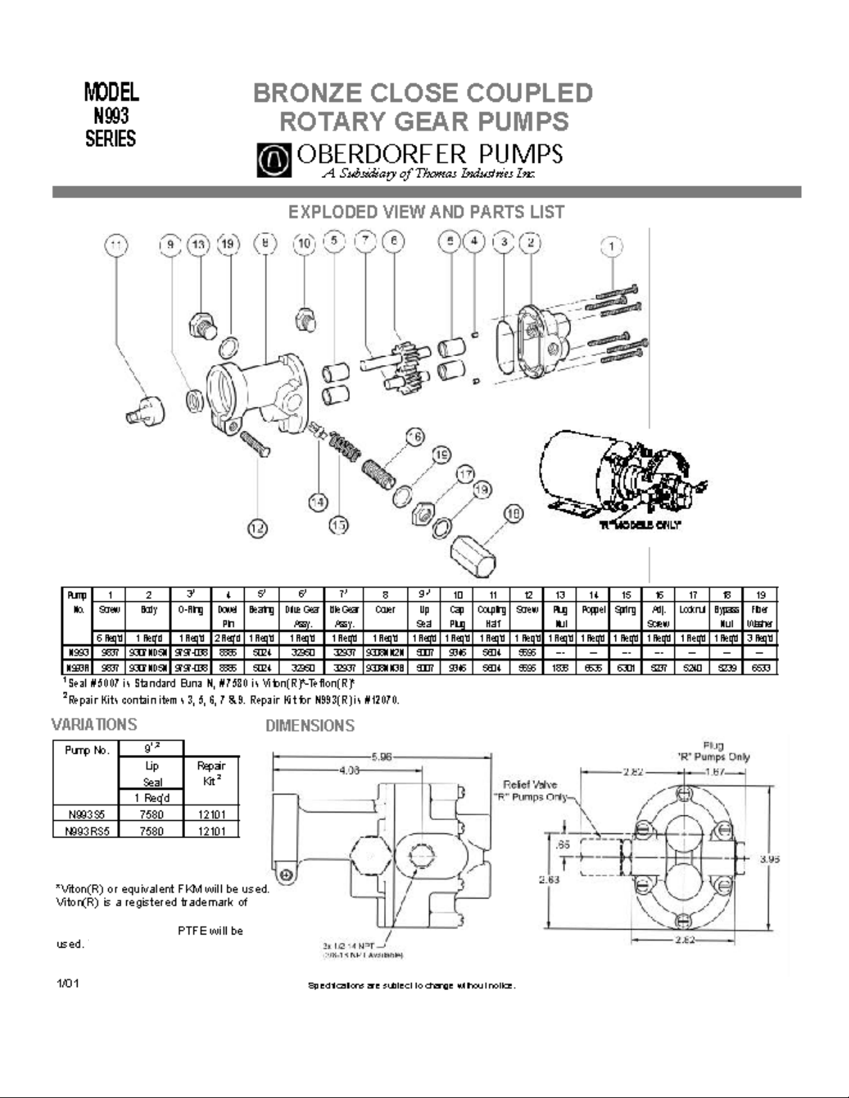
8. Pump Information
8.1 Drive
The pump is driven directly from the electric motor shaft by means of a flexible coupling. An
aluminum adapter connects the pump to the motor.
The adapter is a type “C–Face”.
8.2 Suction Lift
A rotary gear pump is capable of lifting water on the suction side as high as 20 feet. Though
gear pumps are self-priming, a foot valve is recommended.
A wet prime is required for the first dry start. Liquid retained in the system and gear chambers
serves to wet the pump during subsequent starts.
8.3 Rotation
The pump motor supplied by the factory has a clockwise shaft rotation as viewed from the
pump head. Reversing the motor rotation will reverse the “In” and “Out” ports.
To reverse single-phase motors, find the illustrations on the inside of the junction box cover or
on the motor name plate.
34
Page 40

35
Page 41
36
Page 42

Notes:
37
Page 43

Appendix A – Reference Charts
Reference Chart % Propylene Glycol
Weight %
Propylene
Glycol
20 19.4 19.9 1.3565 15.4
21 20.4 19.0 1.3575 16.0
22 21.4 18.0 1.3586 16.7
23 22.4 17.0 1.3598 17.4
24 23.4 16.0 1.3611 18.4
Volume %
Propylene
Glycol
Freeze
Point °ƒ
Refractive
Index
N
77°ƒ
D
Degree
Brix
Boiling
Point °ƒ
@ 760MM Hg
213°ƒ
25 24.4 15.0 1.3621 18.8
26 25.3 14.0 1.3632 19.6
27 26.4 13.0 1.3643 20.2
28 27.4 12.0 1.3654 20.8
29 28.4 11.0 1.3664 21.4
30 29.4 9.1 1.3674 22.0
31 30.4 8.0 1.3685 22.7
32 31.4 7.0 1.3700 23.6
33 32.4 6.0 1.3714 24.4
34 33.5 4.0 1.3729 25.3
35 34.4 3.0 1.3742 25.1
36 35.5 1.0 1.3755 26.9
37 36.5 0 1.3765 27.5
38 37.8 -2.0 1.3775 28.0
39 38.5 -4.0 1.3785 28.5
40 39.6 -5.0 1.3796 29.1
41 40.6 -7.0 1.3806 29.6
42 41.6 -9.0 1.3816 30.2
43 42.6 -11.0 1.3826 30.7
44 43.7 -13.00 1.3837 31.1
45 44.7 -15.0 1.3847 31.8
46 45.7 -17.0 1.3857 32.4
47 46.8 -19.0 1.3868 33.0
48 47.8 -22.0 1.3878 33.5
49 48.9 -25.0 1.3889 34.1
214°ƒ
216°ƒ
217°ƒ
219°ƒ
220°ƒ
50 49.9 -29.0 1.3899 34.7
51 50.9 -31.0 1.3911 35.5
52 51.9 -33.0 1.3922 35.9
53 53.0 -37.0 1.3936 36.6
54 54.0 -40.0 1.3947 37.2
55 55.0 -43.6 1.3961 38.0
56 56.0 -46.0 1.3968 38.4
57 57.0 -50.0 1.3891 39.1
58 58.0 -53.0 1.39911 39.6
59 59.0 -57.0 1.4002 40.3
60 60.0 -60.0 1.4012 40.7
222°ƒ
222°ƒ
225°ƒ
38
Page 44

Reference Chart % Ethylene Glycol
Weight %
Ethylene
Glycol
20 18.1 17.0 1.3525 13.0
21 19.2 16.5 1.3536 13.7
22 20.1 16.0 1.3546 14.3
23 21.0 14.0 1.3555 14.8
24 22.0 13.0 1.3565 15.4
Volume %
Ethylene
Glycol
Freeze
Point °ƒ
Refractive
Index
N
77°ƒ
D
Degree
Brix
Boiling
Point °ƒ
@ 760MM Hg
216°ƒ
25 22.9 12.0 1.3575 16.0
26 23.9 11.0 1.3585 16.6
27 24.8 10.0 1.3590 17.0
28 25.8 9.0 1.3606 17.7
29 26.7 8.0 1.3615 18.5
30 27.7 7.0 1.3625 19.0
31 28.7 5.0 1.3636 22.8
32 29.6 4.0 1.3645 23.4
33 30.6 2.0 1.3645 20.9
34 31.6 1.0 1.3666 21.5
35 32.6 0.0 1.3677 22.2
36 33.5 -1.0 1.3686 22.8
37 34.5 -3.0 1.3696 23.4
38 35.5 -4.0 1.3707 24.0
39 36.5 -5.0 1.3718 24.6
40 37.5 -8.0 1.3728 28.2
41 38.5 -9.0 1.3729 29.1
42 39.5 -11.0 1.3750 26.5
43 40.5 -13.0 1.3760 27.2
44 41.5 -15.0 1.3770 27.7
45 42.5 -17.0 1.3780 28.2
46 44.0 -20.0 1.3796 29.1
47 45.0 -22.0 1.3806 29.6
48 46.0 -24.0 1.3818 30.2
49 47.1 -26.0 1.3828 30.8
218°ƒ
220°ƒ
221°ƒ
224°ƒ
225°ƒ
50 48.0 -28.0 1.3837 31.3
51 49.1 -31.0 1.3848 31.9
52 50.1 -35.0 1.3858 32.5
53 51.2 -36.0 1.3869 33.1
54 52.2 -38.0 1.3880 33.6
55 53.2 -43.0 1.3889 34.1
56 54.3 -45.0 1.3968 38.4
57 55.3 -50.0 1.3909 35.2
58 56.3 -52.0 1.3919 35.7
59 57.4 -54.0 1.3930 36.4
60 68.4 -58.4 1.3939 36.8
227°ƒ
227°ƒ
230°ƒ
39
Page 45

STANDARD PRODUCTS OPERATION
Pulsafeeder, Inc.
27101 Airport Rd.
Punta Gorda, FL 33982
USA
www.pulsa.com
EUROPEAN UNION
Warren Rupp Europe Limited
PO Box 91
Washington
NE37 1YH England
Telephone: 0191 419 0999
Fax: 0191 418 3500
 Loading...