

Page 1

INSTALLATION
OPERATION
MAINTENANCE
INSTRUCTION
BULLETIN No. 680C
ENGINEERED PUMP OPERATIONS
2883 Brighton Henrietta TL Road
P.O. Box 22909
Rochester, New York, 14692-22909 USA
Manufacturers of Quality Pumps, Fax (716) 424-5619
Controls and Systems http://www.pulsa.com
Telephone (716) 292-8000
Page 2
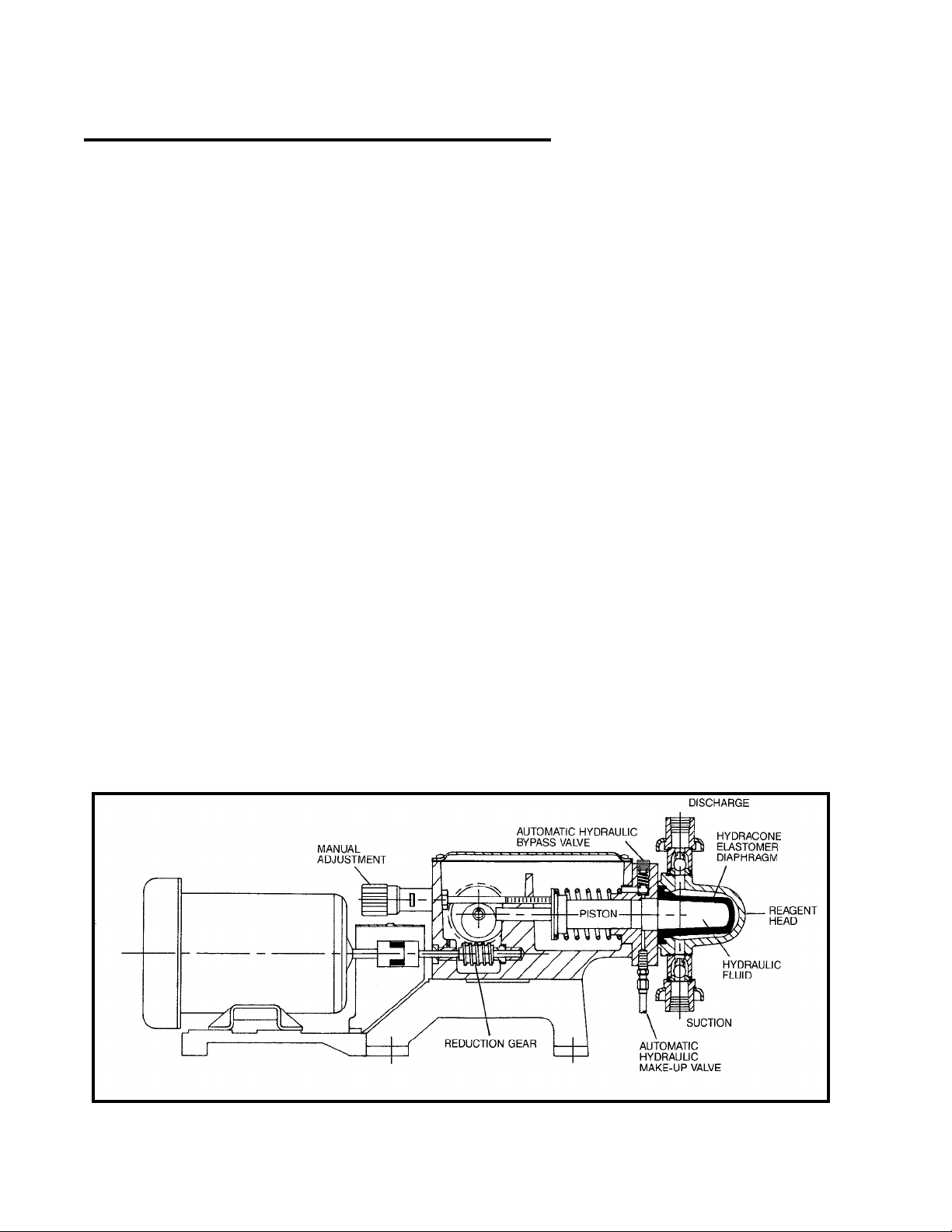
Table of Contents
How it Works ........................................... 2
Installation Tips ......................................... 4
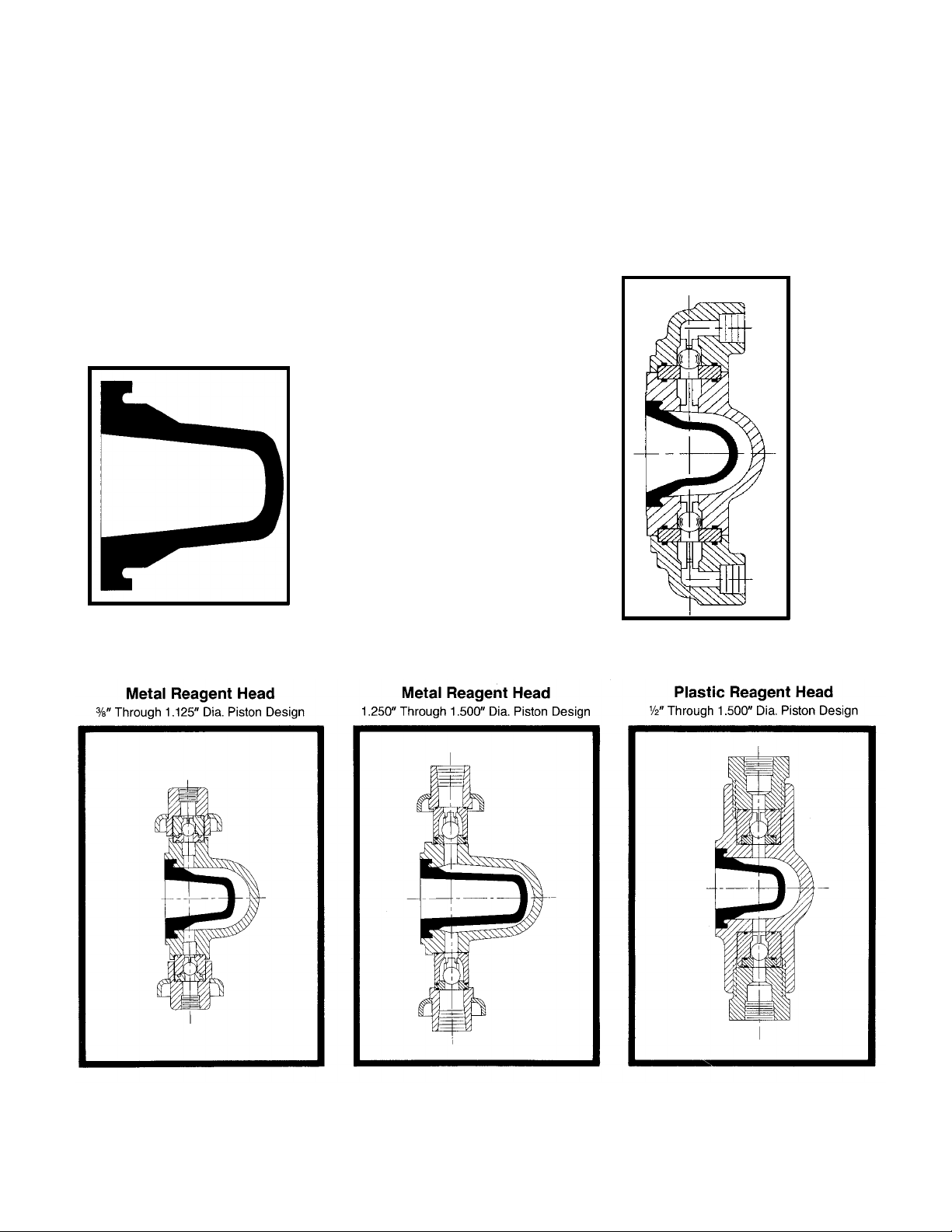
Hydracone Diaphragm
Figure 2
The HYDRACONE elastomer
diaphragm Figure No. 2
isolates product pumped from
the plunger and pump
mechanism.
Start-Up Inspection ...................................... 6
Operation and Maintenance ............................... 9
Storage Instructions ..................................... 12
Trouble Shooting ....................................... 13
How it Works:
Figure 1
A standard foot mounted
motor drives a wormshaft at
constant speed. Through
wormgear reduction and
eccentric, a reciprocating
power stroke is transferred to
a plunger. The length of
stroke determines pump The forward movement of the
capacity and can be adjusted plunger pressurizes the
manually to provide pumping hydraulic fluid which expands
range from 0-100% of rating. the elastomer HYDRACONE
However, this plunger does diaphragm in direct relation to
not pump chemicals, but an plunger travel. As diaphragm
exceptionally stable oil having expands, chemical is forced
*
excellent lubricating qualities. from reagent head and out
This makes a perfect discharge check valve. When
pumping medium. plunger starts to return, the
plunger
A special property petroleum oil
tradenamed "PULSAlube" is generally
used as hydraulic fluid. Continual
reference to "oil" as hydraulic medium
implies its
general use rather than its use of
necessity. Check with your
representative or the factory if
substitute oils must be used.
Several elastomers are
offered including Viton and
Hypalon which provide a
*
*
satisfactory chemical
resistance for a wide variety of
corrosive fluids.
hydraulic pressure is released
and HYDRACONE returns to
normal shape. This
diaphragm return, which is not
affected by inlet pressure
conditions, draws in new
chemical under high suction
lift.
*Products of E.I. DuPont
Figure 1.
2
Page 3
Any leakage past the plunger, Any excess pressure buildup Pressure Relief Valve
however slight, is replaced by within the hydraulic chamber
the make-up valve which or reagent head due to A separate process relief
permits flow of replacement accidental valve closure or valve should be installed in
oil from the oil reservoir. line stoppage is relieved the process piping to protect
Replacement is automatic through the automatic piping and sensitive process
because the oil loss allows hydraulic bypass valve. It equipment.
the diaphragm to get out of blows off oil under excess
phase with the plunger thus pressure ahead of the plunger Plastic Reagent Head
creating a vacuum ahead of back into the oil reservoir thus 3/8" Dia. Piston Design
the plunger during the suction terminating the pumping
stroke of the pump. The action and protecting the
make-up valves are factory pump mechanism. Hydraulic
set. bypass valves are factory set
at full design pressure unless
specified differently by
purchaser.
Figure 2.
Figure 5.
Figure 3. Figure 4. Figure 6.
3
Page 4

Installation Tips
Check The Shipment
A standard PULSA Series
shipment includes the pump,
PULSAlube oil, wrenches,
instruction and parts list
packet and replacement parts
if ordered. Unpack carefully,
check packing list and make
sure all parts are received.
Check voltage of electric
motor against the service to
be used.
NOTE: Most 680 models will
Discharge Pressure:
operate without bolting down.
However, it is important to
have a solid and level
foundation so that a minimum
of vibration is evident.
Continual vibration can
loosen gaskets and pipe
connections.
All 680 models are designed
for continuous service at the
rated discharge pressure. To
prevent liquid flow through, it
is necessary that discharge
pressure be at least 5 psi
above suction pressure.
When pumping downhill a
3. Check motor alignment back pressure valve should
and reagent head and be placed in the discharge
valve bolt tightness before line.
operation. Follow bolt
torque readings carefully.
Locating the 680C Pumps:
PULSA 680C pumps are
designed to operated under
indoor atmospheric
conditions. It is desirable to
provide a hood or covering for
outdoor service. Alternate oil
or external heating must be
arranged if ambient
temperatures will be below
o o
40 F (4.4 C). Fluid
temperatures entering the
pump must be 40 F (4.4 C) or
o o
greater. Check with factory if
concerned with the suitability
of the operating environment.
1. Check level of pump. Shim
where necessary.
2. Securely bolt to foundation.
Do not distort base.
Flooded Suction Desirable:
Installation will be simpler to
operate if the liquid will flow to
the pump by gravity.
Wherever possible the pump
should be located below the
level of storage vessel.
4
Page 5
Piping: shut off valves. This permits susceptible to dirt and other
easy installation of a contaminants and any
Pipe size and length are calibration tube for calibration accumulation can cause
critical to proper operation of of the pump at start up or any malfunction. Be sure to use a
any metering pump. A future date. A tee in the pipeline strainer in the suction
restricted discharge or starved discharge piping is a must on line between the suction shut
suction condition spells a good installation because it off valve and the pump
immediate failure to any permits ease of mounting a suction valve, 100 mesh
metering pump installation. A pressure gauge to check screen is preferred.
separate brochure entitled discharge pressure at the
"Designing a Successful pump and setting the Flush Piping System:
Metering Pump Installation" is hydraulic bypass valve during Whether new or old piping is
provided to assist Engineers start up and future used, all lines should be
responsible for piping system maintenance functions. To flushed with a clean liquid or
design. Copies are available prevent strain on the pump air before connecting the
upon request (Technical fittings use pipe straps and pump to carry out pipe scale
Sheet 304). Inlet piping must braces. Do not allow the or other foreign material.
be at least equal in size to weight of the piping to be Make sure flushing liquid is
pump inlet connection. supported by a pipe union, the compatible with the chemical
valve fitting or other portion of to be pumped.
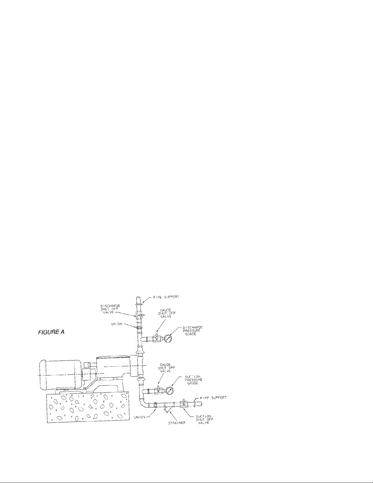
Figure A shows the preferred the pump head or leaks will
piping configuration for a occur. An air leak at a union Metal Reagent Head
good metering pump or other fitting in the suction Models:
installation. A good piping piping can severely affect
installation metering accuracy and is The metal reagent head
addresses present and future extremely difficult to detect. In assembly is provided in
requirements of the metering assembly of piping, use pipe several alloys. Piping of
system. Plan for shut off thread tape or a compound similar alloy should be
valves and unions or flanges compatible with the product selected. Dissimilar materials
installed on both suction and handled. If rigid piping is used can cause galvanic corrosion.
discharge lines. This allows we suggest bolting the pump
inspection of the check valves to its foundation. Do not backweld piping to the
without draining long runs of valve housings without first
pipe. Install a tee in the Use Strainers: removing the valve housings
suction and discharge piping from the pump as excessive
between the pump and the Pump check valves are heat can damage the reagent
head and other parts. Tie
bars must be positioned on
the valve housing before
welding.
Plastic Reagent Head
Models:
Care must be exercised when
making connections on plastic
reagent head models.
Excessive tightening can
distort or break the plastic
materials. Tubing should be
rated for the highest discharge
pressure expected. DO NOT USE
METAL PIPING.
5
Page 6

Start-Up
Final Inspection: Priming Process Head:
Inspection
Every 680C metering pump is
tested for correct capacity at
maximum pressure capability
of the hydraulic bypass valve
before shipment. The
diaphragm cavity is fully
primed and remains so for
shipment. For shipping
purposes the gear and
hydraulic reservoir oil have
been removed. Sufficient
fresh PULSAlube oil is
included with the shipment for
refilling the gear and hydraulic
reservoirs.
Warning
1. Do not run pump without
oil.
2. Do not remove main gear
box cover while pump is
running.
3. Do not run pump with
coupling guard removed.
4. Do not put hands or fingers
in gear box or reservoir
when pump is running.
Filling Gear and Oil
Reservoirs:
Remove the pump cover and
fill both reservoirs with
PULSAlube oil to the top of
the gear box partition. Do not
overfill. PULSAlube oil is
compounded to serve as both
gear lubricant and hydraulic
transfer fluid. Check with
factory if substitute oils must
be used.
The cover assembly
incorporates a free acting
diaphragm to allow breathing
of the reservoir and at the
same time seal the reservoir
from the atmosphere. Be
sure the diaphragm is
properly positioned when
replacing the cover so that it
will seal on the gear box.
Because of the pump's small 1. Open the suction line and
size and light weight it discharge line shut off
sometimes receives severe valves.
handling during shipment. 2. If the piping system design
Though physical damage may and the storage tank are
not occur, it is always possible such that the product flows
for parts to move slightly in by gravity to the pump, no
adjustment. This situation priming is required. If
might occur with motor or however, the discharge line
pneumatic control alignment. is under pressure, air will
A quick visual check should be trapped in the process
be made to assure that motor head and it will be
and control shafts have not necessary to remove the
shifted severely out of discharge pressure to
alignment or damage could enable the pump to prime
occur from starting the motor. itself.
If unusual vibration should 3. If the pump must handle a
occur after start up realign the suction lift, it may be
motor and coupling. necessary to manually
prime the reagent head.
Start-up: Remove the discharge
valve by unscrewing the
Since the hydraulic oil system two tie bar bolts and then
is primed at the factory, lifting the valve out. Fill the
priming the process system is head with process fluid, or
all that should be necessary a compatible liquid then
to produce flow. If the replace the valve in the
hydraulic system has same position and retighten
inadvertently been dumped the tie bar bolts.
due to starting up with 4. The pump is now ready for
restricted suction or discharge start-up.
conditions, repriming 5. Start the pump and
procedures under the increase the control setting
maintenance section may to full stroke.
have to be followed before 6. Make a brief check to
pump calibration can begin. assure that the pump is
producing the approximate
flow desired at the full
stroke setting. Calibration
should not be attempted on
any model until it has run at
least one hour to assure
the pump hydraulic and
reagent head systems have
stabilized.
If the pump does not produce
the approximate flow desired
at the full stroke setting refer
to the Trouble Shooting
Section for possible causes
and refer to Priming
Procedure under the
Operation and
Maintenance Section.
6
Page 7

To Adjust Flow Rate; Calibration: This is caused by
Figure B.
All pumps are tested on water and valve inefficiencies.
The 680C PULSA pumps are at room temperature with 7 Capacity at atmospheric
provided with a micrometer foot flooded head at full rated pressure will be nearly that of
knob adjustment for changing pressure. Any curves calculated displacement. As
length of stroke while in supplied by Pulsafeeder the discharge pressure
operation or idle. NOTE: The would be representative of increases there will be a
external auto locking knob this test and can only be used corresponding decrease in
must be fully disengaged prior as a guideline. capacity at a rate of
to adjustment. When approximately 1% per 100 psi
adjustment is complete the All pumps must be calibrated increase.
lock will automatically engage under actual operating
to prevent drifting of the conditions for the operator to
stroke setting. Turn know the proper adjustment
adjustment knob clockwise to for particular outputs. A
increase flow and typical displacement chart is
counterclockwise to decrease shown in Figure C. Note that
flow. The adjustment knob is output is linear with respect to
read directly in percent of micrometer settings but that
stroke length. These increase in discharge
indications can be converted pressure decreases output
to volumetric or weight units slightly and describes the line
by calibration conversion parallel to that at atmospheric
charts. pressure.
compression of hydraulic oil
Figure B
7
Page 8

Figures D and E show two PULSA pumps supplied with
typical piping arrangements automatic controls, either
for performing pump pneumatic or electronic, are
calibration. It is desirable to accompanied by separate
calibrate from the suction side instructions on output
of the pump so the pump will adjustment and calibration.
be operating under actual or
comparable discharge
conditions.
Check the capacity several
times at three different stroke
length settings and record
them on linear graph paper.
For all stable conditions,
these points should describe
a straight line.
8
Page 9

Operation and
Maintenance
The preceding instructions
have assisted you in proper
installation and start-up of
your 680C pump. The
following sections are
arranged to assist in
maintaining proper pump
operation and trouble
shooting any problems that
might develop during start-up
or thereafter.
Accurate records in the early
stages of pump operation will
reveal the type and amount of
maintenance that will be
required. A preventative
maintenance program based
on these records will insure
trouble free operation. It is
not possible in these
instructions to forecast the life
of such parts as the
diaphragm, check valves and
other parts in contact with the
product you are handling.
Corrosion rates and
conditions of operation affect
the useful life of these
materials so an individual
metering pump must be
gauged according to
particular service conditions.
HYDRACONE Diaphragm 5. Adjust the stroke length
Inspection (capacity) to maximum.
6. Remove the reservoir
The HYDRACONE cover assembly.
diaphragm is an elastomeric 7. Remove the coupling
material which stretches on guard.
each displacement of the 8. Rotate the motor
plunger. It can be damaged coupling until the pump
by the following: piston is withdrawn to full
suction stroke (toward
1. Chemical attack. drive motor end).
2. Mechanical damage 9. Loosen the hydraulic
from trash or abrasives. bypass valve screw
3. High temperature located on top of the
(Maximum 180 F, 2.2 C). hydraulic pumphead to
4. Low temperature (below be sure all hydraulic
5. Suction pressure in relieved from behind the
Service conditions will properly dispose of oil
determine life of the and product leakage that
HYDRACONE and dictate the will occur when
replacement schedule. disassembling head and
To Inspect HYDRACONE 11. Remove the inlet check
Diaphragm valve to drain reagent
1. Remove all pressure extreme caution if
2. Lock out motor. and wear proper
3. Close the inlet and outlet protective clothing.
4. Break the union or bolts and rinse the head
o o
40 F, 4.4 C). pressure has been
excess of 20 psig. diaphragm.
from the piping system. product is hazardous
shut-off valves. 12. Remove reagent head
flanges on the piping. in water or a compatible
o o
10. Arrange to catch and
valving.
head and cavity. Use
liquid.
Figure 7. Figure 8. Figure 9.
9
Page 10

13. Diaphragm can be 3. Connect inlet piping.
removed from the 4. With discharge line 8. Add PULSAlube oil to
reagent head by applying bypassed around front and rear oil
air pressure to one of the process or to drain, start reservoirs to bring oil
valve ports while motor and prime reagent level up to top of
blocking the other. Be head. partition.
sure diaphragm is 5. Set stroke length 9. After pump has run for
directed away from adjustment to maximum several hours, again
personnel so that it does stroke. check for any last traces
not strike the body when 6. If not already lose, of air at the bypass valve.
being expelled from the counting turns, loosen
head. the hydraulic bypass Check Valve
14. Diaphragms which are valve located at the top
Figure 7, 8, 9 and 10
punctured or show of the hydraulic system
evidence of tearing or to atmosphere and any Operating experience on
abrasion at the sealing air present will vent back thousands of installations has
edge should be into the gearbox oil indicated that many pump
replaced. If diaphragm reservoir as the troubles have to do with check
shows evidence of automatic make-up valve valves. Problems usually
hardening so as to be fills the piston/diaphragm stem from (a) an
non-flexible it should be chamber. Air bubbles accumulation of trash
replaced. will be evident at the vent between the valve and seat,
hole, top center of pump (b) corrosion which damages
Repriming Hydraulic head in back of return seating surfaces, (c) erosion
Systems on HYDRACONE spring. from high velocity flow, or (d)
Models 7. When last traces of air normal physical damage after
have been expelled extended service.
1. Reassemble diaphragm retighten the bypass
and reagent head, valve the same number When inspecting the valves,
tightening all bolts of turns or to a desired separate the assembly and
securely and evenly. setting using a pressure examine the components for
2. Reassemble valve gauge in the process wear, damage or
housing, valves, seats line. Approximately a 1/2 accumulation of solids. A ball
and seat gaskets and turn more after process valve seat should have a
take care in inserting pressure setting has sharp 90 edge, free of any
o
gaskets that they are been reached will seat nicks or dents. Hold the ball
properly placed. Tighten valve. The valve can be firmly on the seat and
securely. set higher if desired but examine against a light. If
do not exceed MAX. light is visible between the two
OPERATING then replace the seat and/or
PRESSURE indicated on ball.
the nameplate.
When reassembling after
cleaning or replacement be
sure to use new seals.
10
Page 11

Hydraulic Make-up Valves To adjust the valve to a lower 3. Restricted flow to the
Figure 12
set pressure, turn counter- pump causing the make-
clockwise. up valve to operate. If an
Hydraulic make-up valves are inlet strainer is plugged,
designed to maintain the To check pressure setting it is or someone closes an
correct volume of oil in the necessary to install a gauge in inlet valve thereby
hydraulic system between the the discharge line between restricting flow of fluid to
piston and the diaphragm. the pump and a shut off valve. the pump, the diaphragm
No adjustment or attention is With the pump operating at is then unable to follow
required, provided the oil is maximum stroke a gradual movement of the
clean and free of moisture closing of the shut off valve plunger. The vacuums
and chemical contamination. will cause the bypass valve to created between the
Since the valve operates only reach its cracking pressure diaphragm and the
occasionally and with very which will be observed on the plunger upset the makelittle movement it is not gauge. When the bypass up valve allowing oil to
considered a normal valve is set for maximum replace the vacuum
replacement item in a service pump operating pressure condition. This excess
schedule. If the valve is (shown on nameplate), oil will be displaced
replaced because of cracking pressure is slightly through the hydraulic
corrosion or fouling be sure above maximum operating bypass valve on the
tape or sealant is used on the pressure so that it does not discharge stroke of the
pipe threads to assure an air weep during normal pump plunger. Undersized
tight seal. operation. Dead head (restrictive) piping must
dumping pressure can be be avoided (see "Piping"
Hydraulic Bypass Valve considerably higher than page 5).
cracking pressure on some
The bypass valve is an large piston, fast stroke rate Any unusual condition in the
adjustable spring loaded models, so the internal system which prevents free
valve. It is designed to protect bypass valve should not be movement of the diaphragm
the pump against excessive considered a safety valve for will cause a recirculating
hydraulic pressure. The valve protection of the process condition between the makeis factory set to the setting piping and instrumentation. A up valve and the hydraulic
specified on the specification separate process relief valve bypass valve. Continuous oil
data sheet or set to allow should be used for this recirculation against the
operation at the maximum purpose. bypass valve will eventually
pump pressure, indicated on cavitate the hydraulic prime
the pump nameplate, without It is unusual for a hydraulic plus introduce unnecessary
weeping. bypass valve to operate load conditions within the
during normal pump pump mechanism.
operation. The following
conditions will cause valve
operation:
1. Excessive pressure
buildup in the process
which the pump is
injecting into.
2. A plugged discharge line
or someone shutting off
a valve in the discharge
line while the pump is
operating.
11
Page 12

Lubricating Instructions month interval check the and then start up in
condition of the inlet and accordance with
PULSAlube is a custom blend outlet check valves. These instructions in this
oil with additives for lubrication items along with oil seal manual.
and hydraulic transfer service. inspection should be part of a
(For emergency routine service procedure. Long Term
requirements, a list of
acceptable commercial oils is Oil Capacity For storage longer than 12
available). The diaphragm on months in addition to the
the cover of the gear box The standard 680C metering above, the following
assembly generally protects pump requires approximately procedures should be
the oil from contamination for one quart of PULSAlube oil to followed.
extended periods of time. A fill both chambers and prime
periodic six month check hydraulic pump head. 1. Every 12 months
should be made for oil level PULSAlube oil is available in PULSAlube oil should be
and possible contamination. one gallon cans, cartons of six drained from the gearbox
(6) one gallon cans, five and hydraulic reservoir.
Under sustained conditions of gallon cans or 55 gallon The gearbox and
high humidity or if water is drums. hydraulic reservoir
present, the oil can become should be flushed with
emulsified and take on a STORAGE INSTRUCTIONS kerosene or petroleum
yellowish color. Change the Short Term base solvent, thoroughly
oil immediately if this occurs dried out with a rag, and
and examine the make-up Storage of PULSA Series then refilled with fresh
valve and other parts for pump for up to 12 months PULSAlube oil.
corrosion. A suction pump after shipment is considered 2. Every 12 months the
similar to a grease gun is short term. Under this motor should be
useful for removing oil from condition the recommended connected to a power
chambers, or it may be storage procedures are as source and the pump
drained from the ports at the follows: operated for a minimum
side of each chamber. of one hour. It is not
1. The pump should be necessary to have liquid
stored indoors at room in the reagent head
temperature in a dry during this operation but
environment. the suction and
2. The pump gearbox and discharge ports must be
hydraulic reservoir is to open to atmosphere.
be completely filled with
PULSAlube oil within two After 12 months storage
months after date of Pulsafeeder's warranty
shipment. cannot cover such items as oil
3. The gearbox and seals, gaskets, piston cups
hydraulic reservoir and other items which are
should be inspected subject to deterioration with
every 3-6 months. age. If the pump has been in
Maintain the oil level and storage for longer than 12
assure that no water or months it is recommended
condensation is present, that these items be replaced
follow Procedure II, Step prior to going into service.
A below. Material and labor to
4. It is recommended that recondition or replace this
the stroke length of the class of item is the
pump be adjusted to its purchaser's responsibility.
midpoint and that the For a one year service
To establish a maintenance piston be manually warranty after extended
record and routine procedure, cycled through 3-6 storage the refurbishment and
check lubricant and drive cycles every 6 months. equipment inspection must be
mechanism at three and six 5. Prior to start-up, perform done by a Pulsafeeder
month intervals. At the first six a complete inspection serviceman.
12
Page 13

Maintenance Parts Stock Ordering Parts Trouble Shooting
Pulsafeeder offers a KOPkit When ordering parts always Experience drawn from
which uses a group of specify: thousands of installations has
recommended spares carried shown that there are three
in stock for replacement due 1. Pump model and serial outstanding areas which
to normal wear. The Kit number (stamped on contribute to the bulk of
covers such items as nameplate). operating problems. First and
diaphragm, diaphragm 2. Part number (from parts foremost is installation
gaskets if used, inlet and list), or KOPkit number. conditions - improper location
discharge valve parts, a 3. Material of reagent head and supply, inadequate or
complete set of valve gaskets construction (liquid end restrictive piping to and from
and hydraulic pump head parts). pump; unsupported piping;
gasket. The KOPkit part lack of strainer in suction
number for your pump is Additional Pulsafeeder piping.
indicated on the nameplate. Services
A sufficient quantity of The second major area is
PULSAlube oil should be on FIELD SERVICE - Including check valves. The check
hand for periodic oil changes. pump repair or conversion to valve is the heart of any pump
different services is available and sees more severe service
at nominal cost. than any other part of the
pump. Opening and closing
FACTORY REPAIR - 40 to 140 times per minute,
Complete pump the valve not only receives a
reconditioning. mechanical hammering but
receives it under high velocity
OPERATOR TRAINING corrosive, erosive and
SEMINARS - Conducted by sometimes extreme
experienced factory trained temperature conditions.
service personnel at the Foreign particles, unlevel
factory in Rochester, NY or in mounting, defective seals and
the field. Field trips are improper torquing all too often
available at nominal cost. aggravate even the simplest
application.
The third area is a simple lack
of a routine service policy.
Routine service will catch or
avoid simple operating
problems which can develop
into a crisis if left unattended.
The following is a brief trouble
shooting guide to help identify
and cure any operating
problems you might
experience.
13
Page 14

Trouble Shooting Chart
Difficulty Probable Cause Remedy
Pump Does Not Start 1. Coupling disconnected Connect and align
2. Faulty power source Check power source
3. Blown fuse, circuit breaker Replace -- Locate overload
4. Broken wire Locate and repair
5. Wired improperly Check diagram
No Delivery 1. Motor not running Check power source. Check wiring diagram
2. Supply tank empty Fill with liquid
3. Lines clogged Clean and flush
4. Closed line valves Open pipeline valves
5. Ball check valves held open with solids Clean -- inspect
6. Vapor lock, cavitation Increase suction pressure
7. Prime lost Reprime, check for leak
8. Strainer clogged Remove and clean. Replace screen if
necessary
9. Hydraulic system under-primed Refer to "Repriming Hydraulic System"
10. Check valves installed upside down See check valve illustrations
Low Delivery 1. Motor speed too low Check voltages, hertz, wiring, and terminal
connections. Check nameplate vs.
specifications
2. Check valves worn or dirty Clean, replace if damaged
3. Bypass valve opening each stroke Refer to "Hydraulic Bypass Valve"
4. Calibration system error Evaluate and correct
5. Product viscosity too high Lower viscosity by increasing product
temperature.
Increase pump size.
6. Product cavitating Increase suction pressure. Cool product
as necessary
Delivery Gradually
Drops 1. Stroke adjustment creeping Consult factory. Replace worn parts.
2. Check valve leakage Clean, replace if damaged
3. Leak in suction line Locate and correct
4. Fouled bypass or make-up valve Refer to "Operation and Maintenance"
5. Strainer fouled Clean or replace screen
6. Product change Check viscosity
7. Bypass leakage Correct for bypass valve leakage
Delivery Erratic 1. Leak in suction line Locate and correct
2. Product cavitating Increase suction pressure
3. Entrained air or gas in product Consult factory for suggested venting
4. Motor speed erratic Check voltage, hertz
5. Fouled check valves Clean, replace if necessary
14
Page 15

Difficulty Probable Cause Remedy
Delivery Higher
Than Rated 1. Suction pressure higher than Install back pressure valve or consult factory
discharge pressure for piping recommendations
2. Suction piping too small Increase pipe size -- Install PULSAtrol pulsation
dampener at pump in suction line
3. Back pressure valvae set too low Increase setting
4. Back pressure valve leaks Repair, clean, or replace
Pump Loses Oil 1. Diaphragm ruptured Replace
2. Leaky oil seal Replace
3. Cover gasket leaks Replace or tighten
4. Pump head gasket leaks Replace -- tighten pump head bolts. Seal with
permatex.
5. Gear box overfilled Remove excess oil
Air Continuously 1. Oil in reservoir low Refill to correct level
Bleeds From 2. Hydraulic Bypass valve opening Refer to "Hydraulic Bypass Valve"
Automated Air Bleed continuously
Valve 3. Suction pressure too low Increase pressure
4. Breakdown of oil, temperature high Change oil type, consult factory
Noisy Gearing,
Knocking 1. Discharge pressure too high Reduce pressure or discharge pipe size
2. Water hammer Install PULSAtrol
3. Worn bearings Replace
4. Worn gears Replace gears & check for improper hydraulic
bypass valve setting
5. End play in worm shaft Consult factory
6. Eccentric or worm gear Tighten or replace assembly
7. Bypass valve set too high Readjust (see "Hydraulic Bypass Valve")
Piping Noisy
1. Pipe size too small Increase size of piping, install PULSAtrol
2. Pipe runs too long Install PULSAtrol in line
3. Surge chambers full of liquid Recharge with air or inert gas, replace diaphragm
and recharge
4. No surge chambers used Install PULSAtrols -- pulsation dampeners
Motor Overheats
1. Pump overloaded Check operating conditions against pump design
2. Oil too viscous Consult factory
3. Low voltage Check power supply
4. Loose wire Trace and correct. Check no load amps
15
Page 16

APPENDIX PULSAFEEDER ACCESSORIES
I. PULSATROL INSTALLATION, OPERATION AND REMOVAL INSTRUCTIONS
The PULSAtrol is a pneumatically charged diaphragm type chamber that continuously stores energy. Used on
the inlet it will improve NPSH (Net Positive Suction Head available) characteristics of the suction piping
a
system. On the discharge line it will reduce dangerous peak pressures, eliminate shock waves and if of
sufficient volume will reduce pulsating flow to almost linear.
INSTALLATION
Figures 13 a and b
On both discharge and suction lines it is desirable to mount the PULSAtrol as close to the pump connection as
possible. It can be mounted in any position, but vertical is preferred for ease of charging, draining and
servicing. The air chamber is sealed and will not require replenishing regardless of position. A shut off valve
should always be used between the piping system and PULSAtrol, also a drain valve should always be
installed directly below the PULSAtrol. If the discharge line is open to atmospheric pressure then a back
pressure valve should also be incorporated in the system near the PULSAtrol to assure proper operation.
16
Page 17

OPERATION (Charging the PULSAtrol)
A. Discharge Installation
The air side of the PULSAtrol must be precharged to approximately 50 percent of anticipated mean line
pressure before placing on stream. This will permit the diaphragm to move to a neutral position between the
chambers when operating.
PROCEDURE
Pre Charge Procedure for Discharge Installation
1. Calculate the precharge pressure
Mean Line Pressure (PSIG)
+ Atmospheric Pressure
Absolute Pressure (PSIA)
x Precharge Percentage (80% Max.)
Pressure Absolute
- Atmospheric Pressure
Precharge Pressure (PSIG)
= Precharge Pressure
2. Isolate PULSAtrol from line.
3. Carefully drain off process fluid by opening a drain valve (see recommend piping arrangement).
4. Apply precharge pressure (additional liquid may drain as diaphragm moves).
5. Close drain valve.
6. Place PULSAtrol in stream.
B. Suction Installation (Flooded Suction)
Charge the PULSAtrol with adequate pressure to overcome the static suction head. Start up the pump.
Depress the stem on the charge valve, but only during discharge strokes of the pump, until the gauge indicates
pressure pulses. The diaphragm has not centered allowing the PULSAtrol to accumulate liquid while the
pump is discharging. If too much air becomes released and the gauge will not indicate pressure pulses then
recharge the PULSAtrol and repeat the procedure.
PROCEDURE
Pre Charge Procedure for Suction Installation
1. Isolate accumulator from line.
2. Carefully drain off process fluid by opening a drain valve (see recommended piping arrangement,
attached).
3. Apply 5-10 psi precharge pressure (additional liquid may drain as diaphragm moves).
4. Close drain valve.
5. Bleed off all pressure on the PULSAtrol.
6. Open the valve to put PULSAtrol in stream.
7. Push in on the stem of the charging valve during the discharge stroke of the pump and release
during the suction stroke.
8. Continue this for about 10 times and observe the compound gauge. As accumulator functions, the
needle will go from pressure to vacuum.
C. Suction Installation (Suction Lift)
Consult your PULSA Series representative or the factory for details.
17
Page 18

II. DIAPHRAGM BACK PRESSURE VALVES
Figure 14
Pulsafeeder diaphragm back pressure valves create a constant back pressure without chatter or cycling. A
TFE diaphragm, offering maximum chemical protection and service life, seals spring and bonnet from product.
This diaphragm seals directly on a replaceable seat.
Be sure to install with fluid flow in direction of arrow on valve body. If arrow is missing from plastic valve body,
install with flow exiting out center hole of valve body.
Figure 14
18
Page 19

MAINTENANCE LOG
Pump Model Serial #
Gear Ratio Maximum Flow
Piston Diameter Maximum Pressure
KOPKit
All the above information can be obtained from the pump nameplate. Refer to the Pump Specification Data Sheet
for additional information.
Date Serviced By Maintenance Performed
19
Page 20

CP 9/97 PRINTED IN USA
20
 Loading...