

Page 1
1 EN YR- Instruction Manual Redundancy Module
2
DE YR- Bedienungsanleitung Redundanzmodul
3 FR YR- Manual d'instructions Module de redondance
4 ES YR- Manual de instrucciones Módulo de redundancia
5 IT YR- Manuale di Istruzione Modulo di ridondanza
6 PT YR- Manual de Instruções Módulo de redundância
YR-Series
YRM-Series
Read this first! English 1
Before operating this device please read this manual thoroughly and retain this manual for future reference! This device may only be installed and put into operation by qualified personnel. If damage
or malfunction should occur during operation, immediately turn power off and send unit to the factory for inspection. The unit does not contain serviceable parts. The tripping of an internal fuse is
caused by an internal defect. The information presented in this document is believed to be accurate and reliable and may change without notice. For any clarifications the English translation will be
used.
Intended Use: This device is designed for installation in an enclosure and is intended for general use such as in industrial control, office, communication, and instrumentation equipment. Do not use
this device in equipment, where malfunction may cause severe personal injury or threaten human life.
WARNING
1) Turn power off before working on the device. Protect against inadvertent re-powering.
2) Make sure that the wiring is correct by following all local and national codes.
3) Do not modify or repair the unit.
4) Use caution to prevent any foreign objects from entering the housing.
5) Do not use in wet locations or in areas where moisture or condensation can be expected.
6) Do not touch during power-on, and immediately after power-off. Hot surfaces may cause burns.
Risk of electrical shock, fire, personal injury or death.
Vor Inbetriebnahme lesen! Deutsch 2
Bitte lesen Sie diese Warnungen und Hinweise sorgfältig durch, bevor Sie das Gerät in Betrieb nehmen. Bewahren Sie die Anleitung zum Nachlesen auf. Das Gerät darf nur durch fachkundiges und
qualifiziertes Personal installiert werden. Bei Funktionsstörungen oder Beschädigungen schalten Sie sofort die Versorgungsspannung ab und senden das Gerät zur Überprüfung ins Werk. Das Gerät
beinhaltet keine Servicebauteile. Interne Sicherungen lösen nur bei Gerätedefekt aus. Die angegebenen Daten dienen allein der Produktbeschreibung und sind nicht als zugesicherte Eigenschaften
im Rechtssinne aufzufassen. Im Zweifelsfall gilt der englische Text.
Bestimmungsgemäßer Gebrauch: Dieses Gerät ist für den Einbau in ein Gehäuse konzipiert und zur Verwendung für allgemeine elektronische Geräte, wie z.B. Industriesteuerungen, Bürogeräte,
Kommunikationsgeräte oder Messgeräte geeignet. Benutzen Sie dieses Gerät nicht in Steuerungsanlagen, in denen eine Funktionsstörung zu schweren Verletzungen führen oder Lebensgefahr
bedeuten kann.
WARNUNG
1) Schalten Sie die Eingangsspannung vor Installations-, Wartungs- oder Änderungsarbeiten ab und sichern Sie diese gegen unbeabsichtigtes Wiedereinschalten.
2) Sorgen Sie für eine ordnungsgemäße und fachgerechte Verdrahtun g .
3) Führen Sie keine Änderungen oder Reparaturversuche am Gerät durch.
4) Verhindern Sie das Eindringen von Fremdkörpern, wie z.B. Büroklammern und Metallteilen.
5) Betreiben Sie das Gerät nicht in feuchter Umgebung oder in einer Umgebung, bei der mit Betauung oder Kondensation zu rechnen ist.
6) Gehäuse nicht während des Betriebes oder kurz nach dem Abschalten berühren. Heiße Oberflächen können Verletzungen verursachen.
Missachtung nachfolgender Punkte kann einen elektrischen Schlag, Brände, schwere Unfälle oder Tod zur Folge haben.
A lire avant mise sous tension! Français 3
Merci de lire ces instructions de montage et d'entretien avant de mettre l'alimentation sous tension. Conservez ce manuel qui vous sera toujours utile. Cette alimentation doit être installée par du
personnel qualifié et compétent. Le déclenchement du fusible interne traduit très probablement un défaut au niveau de l'appareil. Si un défaut quelconque apparaît en cours de fonctionnement,
débrancher au plus vite l'alimentation. Dans ce deux cas de figure, il convient de faire contrôler l'alimentation en usine! Les données indiquées dans ce document servent uniquement à donner une
description du produit et n'ont aucune valeur juridique. En cas de divergences, le texte anglais fait foi.
Utilisation: Cet appareil est conçu pour être installé dans une armoire et pour tous les équipements électroniques, tel que l'équipement industriel de commande, l'équipement de bureau, le matériel
de communication et les instruments de mesures. N'utilisez pas cet appareil su r des installations dans lesquels un problème de fonctionnement de l'alimentation pourrait causer des blessures graves
ou menacer la vie humaine.
AVERTISSEMENT
1) débrancher l'installation avant toute intervention sur l'alimentation (ou démontage) et s'assurer qu'il n'y a pas risque de redémarrage.
2) s'assurer que le câblage a été fait selon les prescriptions
3) ne pas effectuer de réparations ou modifications sur l'alimentation
4) veiller à ce qu'aucun objet ne rentre en contact avec l'intérieur de l'alimentation (trombones, pièces métalliques)
5) ne pas faire fonctionner l'appareil dans un environnement humide ou à l'extérieur, non protégé. Ne pas utiliser l'appareil dans un environnement où il peut y avoir de la condensation.
6) ne pas toucher le carter pendant le fonctionnement ou après la mise sous tension. Surface chaude risquant d’entraîner des blessures.
Prendre en compte les points suivants, afin d'éviter toute détérioration électrique, incendie, dommage aux personnes ou mort.
Lea primero! Español 4
Conserve este manual como referencia para futuras consultas. La fuente de alimentación solo puede ser instalada y puesta en funcionamiento por personal cualificado. Por favor lea detenidamente
este manual antes de conectar la fuente de alimentación. Cuando se funde un fusible interno, existe gran probabilidad de un fallo interno en el equipo.Si se produce un fallo o mal funcionamiento
durante la operación, desconecte inmediatamente la tensión de alimentación. En ambos casos, el equipo debe ser inspeccionado en fábrica. La información presentada en este documento es
exacta y fiable en cuanto a la descripción del producto y puede cambiar sin aviso. En casa de duda, prevalece el texto inglés.
Uso apropiado: Este equipo ha sido diseñado para su instalación en un ambiente cerrado y ha sido concebido para uso general en instalaciones de control industrial, oficinas, comunicaciones y
equipos de instrumentación. No emplee esta unidad en equipos, donde un mal funcionamiento puede ocasionar lesiones graves o riesgo mortal.
ADVERTENCIA
1) Desconectar la tensión de red antes de trabajar en la fuente de alimentación. Evite una posible reconexión involuntaria.
2) Asegurarse de que el cableado es correcto de acuerdo a los códigos locales y nacionales.
3) No realizar ninguna modificación o reparación de la unidad.
4) Evitar la introducción en la carcasa de objetos extraños.
5) No usar el equipo en ambientes húmedos. No operar el equipo en ambientes donde se espere la formación de rocío o condensación.
6) No tocar durante el funcionamiento ni inmediatamente después del apagado. El calor de la superficie puede causar quemaduras graves
Riesgo de descarga eléctrica, incendio, accidente grave o muerte.
Page 2
Leggere prima questa parte! Italiano 5
Prima di collegare il sistema di alimentazione elettrica si prega di leggere attentamente le seguenti avvertenze. Conservare le istruzioni per la consultazione futura. Il sistema di alimentazione elettrica
deve essere installato solo da personale competente e qualificato. In caso di intervento del fusibile interno, molto probabilmente l'apparecchio è guasto. Se durante il funzionamento si verificano
anomalie o guasti, scollegare immediatamente la tensione di alimentazione. In entrambi i casi è necessario far controllare l'apparecchio dal produttore! I dati sono indicati solo a scopo descrittivo del
prodotto e non vanno considerati come caratteristiche garantite dell'apparecchio.In caso di differenze o problemi è valido il testo inglese
Uso previsto: Questo apparecchio è previsto per il montaggio in un rack per moduli elettronici, ad esempio per controllori industriali, apparecchiature per ufficio, unità di comunicazione o apparecchi
di misura. Non utilizzare questo apparecchio in apparati o impianti dove il malfunzionamento può causare danni alla persona o pericolo di vita.
AVVERTENZA
1) Prima di eseguire interventi di installazione, di manutenzione o di modifica scollegare la tensione di rete ed adottare tutti i provvedimenti necessari per impedirne il ricollegamento non intenzionale.
2) Assicurare un cablaggio regolare e corretto.
3) Non tentare di modificare o di riparare da soli l'apparecchio.
4) Impedire la penetrazione di corpi estranei nell'apparecchio, ad esempio fermagli o altri oggetti metallici.
5) Non far funzionare l'apparecchio in un ambiente umido. Non far funzionare l'apparecchio in un ambiente soggetto alla formazione di condensa o di rugiada.
6) Non toccare quando acceso e subito dopo lo spegnimento. La superficie calda può causare scottature.
Il mancato rispetto delle seguenti norme può provocare folgorazione elettrica, incendi, gravi incidenti e perfino la morte.
Leia primeiro! Portuguès 6
Recomendamos a leitura cuidadosa das seguintes advertências e observações, antes de colocar em funcionamento a fonte de alimentação. Guarde as Instruções para futura consulta, em casos de
dúvida. A fonte de alimentação deverá ser instalada apenas por profissionais da área, tecnicamente qualificados. Se o fusível interno se fundir, é grande a possibilidade de existir um defeito no
aparelho. Se por acaso, durante a utilização ocorrer algum defeito de funcionamento ou dano, desligue imediatamente a tensão de alimentação. Em ambos os casos, será necessária uma
verificação na Fábrica! Os dados mencionados têm como finalidade somente a descrição do produto, e não devem ser interpretados como propriedades garantidas no sentido jurídico. Em caso de
duvidas aplica-se o texto em inglês.
Utilize: Este aparelho foi concebido para ser montado dentro de invólucros, caixas ou armários para aparelhos eletrônicos em geral, como, por exemplo, comandos de instalações industriais,
aparelhos para escritórios, aparelhos de comunicação ou instrumentos de medida e quadros eléctricos. Não utilize este aparelho em instalações, nos quais um defeito de funcionamento poderá
causar danos graves ou significar risco de morte.
ATENÇÃO
1) Antes de trabalhos de instalação, manutenção ou modificação, desligue a tensão de alimentação, protegendo-a contra uma nova ligação involuntária.
2) As ligações devem ser efectuadas apenas por profissionais competentes.
3) Não efectue nenhuma modificação ou tentativa de reparação no aparelho. Quando necessário contacte o seu distribuidor.
4) Proteger a fonte de alimentação contra a introdução inadvertida de corpos metálicos, como por ex., clipes ou outras peças de metal.
5) Não usar o aparelho em ambientes húmidos. Não usar o aparelho em ambientes propensos a condensações.
6) Não tocar enquanto estiver em funcionamento, nem após a desligar. A superficie poderá estar quente e provocar lesões.
Product Description
The reliability of the DC supply can be increased by using redundant systems. To achieve
redundancy, one extra power supply must be installed in order to deliver the required current in
case one power supply in the system fails. Each individual power supply must be isolated from the
others with diodes or Mosfets to avoid that a defective unit can become a load for the rest of the
system. Therefore redundancy modules are utilized.
Recommendations for Redundant Applications
- Use separate input fuses or breakers for each power supply.
- If possible, use 3-phase power supplies to gain functional safety if one phase fails.
- When Single-phase power supplies are utilized connect them to different phases.
- It is desirable to set the output voltages of all power supplies to the same value (±0.5V) to avoid
a false signal of the DC-ok signal.
- Set power supplies to “Parallel Use” if this option is available.
- Use separate mains systems for each power supply whenever it is possible.
+
Input 1
-
+
Input 2
-
Typical 1+1 redundant system for load currents up to 20A
Typisches 1+1 redundantes System für Ströme bis zu 20A
A não observância ou o incumprimento dos pontos a seguir mencionados, poderá causar uma descarga elétrica, incêndios, acidentes graves ou morte.
Gerätebeschreibung
Die Zuverlässigkeit einer DC-Versorgung kann durch redundante Systeme erhöht werden. Hierbei
muss ein zusätzliches Gerät in „Reserve“ installiert werden, das dann den nötigen Laststrom zur
Verfügung stellt, wenn ein Gerät im System ausfällt. Die einzelnen Geräte müssen mittels Dioden
oder Mosfets entkoppelt sein,um nicht im Fehlerfall zur Last für die restlichen Stromversorgungen
zu werden. Hierzu werden Redundanzmodule verwendet.
Empfehlungen für redundante Anwendungen
- Für jede Stromversorgung sind eigene Sicherungen zu verwenden.
- Bei 3-Phasen-Systemen erreicht man einen zusätzlichen Schutz bei Ausfall einer Phase.
- Stromversorgungen mit 1-Phasen Eingang möglichst an unterschiedliche Phasen anschließen.
- Es ist wünschenswert, die Ausgangsspannung der Stromversorgungen auf annähernd gleichen
Spannungswert (±0.5V) einzustellen, um falsche DC-OK Signale der Netzgeräte zu vermeiden.
- Stromversorgungen auf „Parallel Use“ stellen, falls diese Option verfügbar ist.
- Es ist vorteilhaft, für jede Stromve rsorgung ein separates Speisenetz zu ver wenden.
YR2.DIODE YRM2.DIODE YR40.241/242/482, YR80.241/242 YR40.245
+
-
Input 1
Alarm
contact
Output
Chassis
Ground
Input 2
Alarm
contact
Input 1
Input 2
+
-
+
-
control
control
+
-
Output
Chassis
Ground
control
+
Input
-
Chassis
Ground
Typisches N+1 redundantes System mit vier 40A Stromversorgungen für Ströme bis zu 120A
120A
Load
+
Output
-
+
-
Output
Chassis
Ground
Input 1
ok
+
Input 1
-
+
Input 2
-
Input 2
ok
Input
Voltage
Monitor
Input
Voltage
Monitor
Alarm
Relay
Alarm
Relay
Typical N+1 redundant system with four 40A power supplies for load current up to 120A
Failure
Monitor
Failure
Monitor
+-+
+ +
- -
DC-
24V,20A
OK
QT20.241
Power
Supply
L1 L2 L3 PE
I I I I I I
L1
L2
L3
PE
Input
Input
1
YR40.241
Redundancy
Module
Output
+
-
20A
Load
-
+ +
- -
24V,20A
QT20.241
Power
Supply
L1 L2 L3 PE
DCOK
2
QT40.241
40A Power Supply
Parallel Use
Single Use
L1 L2 L3 PE
I I I I I I
L1
L2
L3
PE
Germany +49 89 9278 0 www.pulspower.de
China +86 512 62881820 www.pulspower.cn
France +33 478 668 941 www.pulspower.fr
North America +1 630 587 9780 www.pulspower.us
Austria +43 27 64 32 13 www.pulspower.at
Singapore +65 6684 2310 www.pulspower.sg
Switzerland +41 56 450 18 10 www.pulspower.ch
United Kingdom +44 845 130 1080 www.pulspower.co.uk
+ +
DCOK
24V, 40A
QT40.241
Output
1
-
-
40A Power Supply
DC-
Parallel Use
OK
Single Use
Input
2
+
-
L1 L2 L3 PE
+ +
24V, 40A
+
YR80.241
Redundancy
Module
Input
- -
+
QT40.241
40A Power Supply
DC-
Parallel Use
OK
Single Use
24V, 40A
+ +
- -
L1 L2 L3 PE
I I I I I I
- -
+
YR80.241
Redundancy
Module
Input
+
Headquarters:
-
Output
1
-+ -
Input
2
QT40.241
40A Power Supply
Parallel Use
Single Use
L1 L2 L3 PE
DCOK
24V, 40A
+ +
- -
PULS GmbH
Arabellastrasse 15
D-81925 Munich
Germany
www.pulspower.com
Page 3

YR: Redundancy Modules Instruction Manual
YR: Bedienungsanleitung für Redundanzmodule
Technical Data 1) Technische Daten
Number of inputs / outputs Anzahl Eingänge / Ausgänge 2 / 1 2 / 1 2 / 1 2 / 1
Decoupling Element Entkoppelelement Diode Diode Mosfet Mosfet
Suitable Power Supplies Geeignete Stromversorgungen all series all series all series all except QT20,
Input Voltage Eingangsspannung nom. DC 12-48V
Input Voltage Range Eingangsspannungsbereich - 9-60Vdc
Output Current Nominal Ausgangsstrom Nominal nom. 0-20A 0-20A 0-40A 0-40A
Up to 5 seconds Bis zu 5 Sekunden max. 20-32A 20-32A 40-65A 40-65A
Overload, Short-circuit
2)
Überlast, Kurzschluss 2) max. 25A 25A 65A 26A
Input Current Nominal Eingangsstrom Nominal nom. 2x 0-10A 2x 0-10A 2x 0-20A 2x 0-20A
Up to 5 seconds Bis zu 5 Sekunden max. 2x 10-16A 2x 10-16A 2x 20-32.5A 2x 20-32.5A
Overload, Short-circuit 2) Überlast, Kurzschluss 2) max. 2x 12.5A 2x 12.5A 2x 32.5A 2x 13A
Peak Input Current (per input) Eingangsspitzenstrom (pro Eingang) max. 150A for 10ms 150A for 10ms 1000A for 1ms 1000A for 1ms
Reverse Current 4) (per input) Rückwärtsstrom
Voltage Drop (Input to Output) Spannungsabfall (Eingang zu Ausgang) typ. 780mV
Power Losses in normal mode Verlustleistung im Normalbetrieb typ. 7.8W
at no lo ad im Leerlauf typ. 0W 1W 0.7W 0.2W
Low-Input-Voltage Alarm Contacts Eingangsspannungsüberwachungsrelais - no / nein yes / ja no / nein no / nein
Alarm threshold level (Alarm Meldeschwelle) nom. - 21.5V (±0.5V) - Operational Temperature Range Betriebstemperaturbereich nom. -40°C - +70°C -40°C - +70°C -40°C - +70°C -40°C - +70°C
Output Derating Ausgangsstromrücknahme +60°C to +70°C 0.5A/°C 0.5A/°C 0A/°C 1A/°C
Storage Temperature Range Lagertemperaturbereich nom. -40°C - +85°C -40°C - +85°C -40°C - +85°C -40°C - +85°C
Humidity 6) Feuchte
6)
IEC 60068-2-30 5 - 95% r.H. 5 - 95% r.H. 5 - 95% r.H. 5 - 95% r.H.
Vibration Schwingen IEC 60068-2-6 2g 2g 2g 2g
Shock Schocken IEC 60068-2-27 30g 6ms, 20g 11ms 30g 6ms, 20g 11ms 30g 6ms, 20g 11ms 30g 6ms, 20g 11ms
Degree of Pollution (non-conductive) Verschmutzungsgrad (nicht leitend) EN 50178 / IEC 62103 2 2 2 2
Degree of Protection Schutzart EN 60529 IP20 IP20 IP20 IP20
Class of Protection Schutzklasse IEC 61140 III
Over-Temperature Protection Übertemperaturschutz OTP no / nein no / nein no / nein no / nein
Reverse Input Polarity Protection Eingangsverpolschutz - yes / ja yes / ja yes / ja yes / ja
Penetration Protection Fremdkörper Eindringschutz max. 3.6mm 3.6mm 3.6mm 3.6mm
Return Voltage Resistance 8) Rückspeisefestigkeit
Isolation Against Housing Isolationsfestigkeit gegen Gehäuse min. 500Vac, 5MOhm 500Vac, 5MOhm 500Vac, 5MOhm 500Vac, 5MOhm
Dimensions 9) (WxHxD) Abmessungen
Weight Gewicht max. 290g, 0.64lb 350g, 0.77lb 340g, 0.75lb 280g, 0.62lb
Footnotes see next page / Fussnoten auf der nächsten Seite
Technical Data 1) Technische Daten
Number of inputs / outputs Anzahl Eingänge / Ausgänge 1 / 1 2 / 1 2 / 1 2 / 1
Decoupling Element Entkoppelelement Mosfet Mosfet Mosfet Mosfet
Suitable Power Supplies Geeignete Stromversorgungen all except QT20,
Input Voltage Eingangsspannung nom. DC 12-28V
Input Voltage Range Eingangsspannungsbereich - 8.4-36.4Vdc 20.4-64.4Vdc 8.4-36.4Vdc 8.4-36.4Vdc
Output Current Nominal Ausgangsstrom Nominal nom. 0-40A 0-40A 0-80A 0-80A
Up to 5 seconds Bis zu 5 Sekunden max. 40-65A 40-65A 80-130A 80-130A
Overload, Short-circuit
Input Current Nominal Eingangsstrom Nominal nom. 0-40A 2x 0-20A 2x 0-40A 2x 0-40A
Up to 5 seconds Bis zu 5 Sekunden max. 40-65A 2x 20-32.5A 2x 40-65A 2x 40-65A
Overload, Short-circuit 2) Überlast, Kurzschluss 2) max. 22A
Peak Input Current (per input) Eingangsspitzenstrom (pro Eingang) max. 1500A for 1ms 1000A for 1ms 1500A for 1ms 1500A for 1ms
Reverse Current 4) (per input) Rückwärtsstrom
Voltage Drop (Input to Output) Spannungsabfall (Eingang zu Ausgang) typ. 150mV
Power Losses in normal mode Verlustleistung im Normalbetrieb typ. 6.2W
at no lo ad im Leerlauf typ. 0.12W 0.62W 0.7W 0.2W
Low-Input-Voltage Alarm Contacts Eingangsspannungsüberwachungsrelais - no / nein no / nein no / nein no / nein
Alarm threshold level (Alarm Meldeschwelle) nom. - - - Operational Temperature Range
Output Derating Ausgangsstromrücknahme +60°C to +70°C 1A/°C 1A/°C 0A/°C 2A/°C
Storage Temperature Range Lagertemperaturbereich nom. -40°C - +85°C -40°C - +85°C -40°C - +85°C -40°C - +85°C
Humidity 6) Feuchte
Vibration Schwingen IEC 60068-2-6 2g 2g 2g 2g
Shock Schocken IEC 60068-2-27 30g 6ms, 20g 11ms 30g 6ms, 20g 11ms 30g 6ms, 20g 11ms 30g 6ms, 20g 11ms
Degree of Pollution (non-conductive) Verschmutzungsgrad (nicht leitend) EN 50178 / IEC 62103 2 2 2 2
Degree of Protection Schutzart EN 60529 IP20 IP20 IP20 IP20
Class of Protection Schutzklasse IEC 61140 III
Over-Temperature Protection Übertemperaturschutz OTP no / nein no / nein no / nein no / nein
Reverse Input Polarity Protection Eingangsverpolschutz - yes / ja yes / ja yes / ja yes / ja
Penetration Protection Fremdkörper Eindringschutz max. 3.6mm 3.6mm 3.6mm 3.6mm
Return Voltage Resistance 8) Rückspeisefestigkeit
Isolation Against Housing Isolationsfestigkeit gegen Gehäuse min. 500Vac, 5MOhm 500Vac, 5MOhm 500Vac, 5MOhm 500Vac, 5MOhm
Dimensions 9) (WxHxD) Abmessungen
Weight Gewicht max. 340g, 0.75lb 360g, 0.79lb 440g, 0.97lb 370g, 0.81lb
Footnotes see next page / Fußnoten befinden sich auf der nächsten Seite
2)
Überlast, Kurzschluss 2) max. 22A
12)
Betriebstemperaturbereich
6)
IEC 60068-2-30 5 - 95% r.H. 5 - 95% r.H. 5 - 95% r.H. 5 - 95% r.H.
1)
YR2.DIODE YRM2.DIODE YR40.241 YR40.242
±25%
DC 12-120V
±25% 11)
9-150Vdc
4)
(pro Eingang) max. 2mA 2mA 1mA 1mA
8)
max. 200Vdc 200Vdc 40Vdc 40Vdc
9)
(BxHxT) nom. 32x124x102mm 32x124x117mm 36x124x127mm 36x124x127mm
1)
YR40.245 YR40.482 YR80.241 YR80.242
DC 24-48V
11)
5)
5)
7)
QTD20, SilverLine
±30%
3)
3)
4)
(pro Eingang) max. 1mA 1mA 1mA 1mA
12)
nom. -40°C - +70°C -40°C - +70°C -40°C - +70°C -40°C - +70°C
8)
max. 40Vdc 65Vdc 40Vdc 40Vdc
9)
(BxHxT) nom. 46x124x127mm 46x124x127mm 46x124x127mm 46x124x127mm
10)
10)
7)
±25%
DC 12-28V
18-60Vdc 8.4-36.4Vdc 8.4-36.4Vdc
780mV 5) 72mV 5)72mV
8.8W 5) 2.2W 5)1.7W
III 7) III 7)III
all series all series all series except
DC 24-56V
±15%
DC 12-28V
45A 3) 130A 44A
2x 22.5A 3) 2x 65A 2x 22A
60mV 5) 49mV 5)65mV
1.8W 5) 2.7W 5)2.9W
III 7) III 7)III
±30%
±30%
QTD20, SilverLine
DC 12-28V
QT40, SilverLine
DC 12-28V
±30%
3)
3)
5)
5)
7)
±30%
3)
3)
5)
5)
7)
Page 4
YR: Redundancy Modules Instruction Manual
YR: Bedienungsanleitung für Redundanzmodule
Footnotes of the Specification Tables:
1) All parameters are specified at 24V input voltage (48V for the YR40.482), nominal output
current, 25°C ambient and after a 5 minutes run-in time unless otherwise noted.
2) Ensure that the average output current does not exceed this value. Check the short-circuit
current of the power sources and if the power source can deliver more than this current
combined, use an appropriate fuse on the output.
3) Currents at voltages below 6V.
4) Over the entire temperature range.
5) At 1+1 Redundancy operation (=50% of the nom. output current) and symmetrical input
currents.
6) Do not energize while condensation is present.
7) PE (Ground) connection optional but not required.
8) Loads such as decelerating motors and inductors can feed voltage back to the output of the
redundancy module. The figure represents the maximum allowed feed back voltage.
9) Depth without DIN-rail and connection terminals.
10) At 40A nominal output current
11) Restrictions apply, see notes on page 5
12) The operational temperature range equals the surrounding air temperature measured 2cm
below the unit.
Installation
Use DIN-rails according to EN 60715 or EN 50022 with a height of 7.5 or 15mm.
Use only with the following mounting orientations:
YR2.DIODE, YRM2.DIODE, YR40.241: input terminals on top of the unit
YR40.242, YR40.482, YR40.245, YR80.241, YR80.241: input terminals on the bottom of the unit.
For other orientations see datasheet.
Do not obstruct air flow as the unit is convection cooled.
Ventilation grid must be kept free of any obstructions.
Keep the following installation clearances:
40mm on top, 20mm on the bottom,
5mm on the left and right sides are recommended when the redundancy module is loaded
permanently with more than 50% of the rated output current. Increase the side clearance to
15mm in case the adjacent device is a heat source (e.g. another power supply).
For 1+1 redundant applications, the clearance “A” can be reduced to 0mm in combination with
the following power supplies:
+-+
+ +
- -
Output
Power Supply 1
Input
output current.
Use in hazardous location areas
Units which are marked with "Class I Div 2" are suitable for use in Class I Division 2 Groups A, B,
C, D locations.
Units which are marked with II 3G Ex nA nC IIC T4 Gc are suitable for use in Group II
Category 3 (Zone 2) environments and are evaluated according to EN 60079-0:2009 and EN
60079-15:2010.
WARNING EXPLOSION HAZARDS!
Substitution of components may impair suitability for this environment. Do not disconne c t the unit
or operate the voltage adjustment unless power has been switched off or the area is known to be
non-hazardous. A suitable enclosure must be provided for the end product which has a minimum
protection of IP54 and fulfils the requirements of the EN 60079-15:2010.
Input
Input
1
Redundancy
Module
Output
+
-
Load
-
2
Power Supply 2
+ +
AA
Output
- -
Input
CE Marking
CE mark is in conformance with EMC directive 2004/108/EC, the low-voltage directive (LVD)
2006/95/EC and the RoHS directive 2011/65/EU.
EMC Immunity: EN 61000-6-1, EN 61000-6-2
EMC Emission: EN 61000-6-3, EN 61000-6-4, FCC Part 15 Class B
Input Voltage Alarm Contacts (only for YRM2.DIODE)
Both input voltages are monitored individually. If one input voltage is too low or completely
removed, it will be indicated by an alarm relay contact. The corresponding green LED on the front
of the unit will go off in this case.
Contact is closed when the input voltage is above 21.5V (±0.5V)
Contact ratings: max.: 60Vdc 0.3A, 30Vdc 1A, 30Vac 0.5A, resistive load, min. current 1mA
Dielectric Strength
The input and output voltages are floating and have no ohmic connection to ground.
Type and factory tests are conducted by the manufacturer. Field tests may be conducted in the
field using the appropriate test equipment which applies the voltage with a slow ramp (2s up and
2s down). Connect all input and output terminals together before the test is conducted.
When testing, set the cut-off current sett ings to the value in the table below.
Input or Output Alarm Signals to
to Chassis Input, Output or Chassis
Type Test (60s) 500Vac 500Vac
Factory Test (5s) 500Vac 500Vac
Field Test (5s) 500Vac 500Vac
Cut-off current setting >2mA >2mA
Redundancy Module Power Supplies
YR2, YRM2 CD5, CS5, QS5, CS10,
CT10, QS10
YR40.241 *) QS20, CPS20, QT20
YR40.242 *) QS20, CPS20
YR40.245 **) QS40, XT40
YR40.482 *) QS20, CPS20, QT20,
QS40, QT40
YR80.241 **) QS40, QT40, XT40
YR80.242 **) QS40, XT40
*) Additional all unit with less or equal 10A nominal
output current.
**) Additional all unit with less or equal 20A nominal
Fußnoten der technischen Tabellen:
1) Alle Werte gelten bei 24V Eingangsspannung (48V beim YR40.482), Nennausgangsstrom,
25°C Umgebungs-temperatur und nach einer Aufwärmzeit von 5 Minuten, wenn nichts
anderes angegeben ist.
2) Der mittlere Ausgangsstrom darf diesen Wert nicht überschreiten. Überprüfen Sie die
möglichen Ausgangsströme auch im Fehlerfall oder Kurzschluss und verwenden Sie
gegebenenfalls eine geeignete Vorsicherung.
3) Strom bei Spannungen kleiner 6V
4) Über den gesamten Arbeitstemperaturbereich.
5) Bei 1+1 Redundanzbetrieb (= 50% des nominalen Ausgangsstroms) und symmetrischen
Eingangsströmen.
6) Nicht betreiben, solange das Gerät Kondensation aufweist.
7) PE Verbindung erlaubt, aber nicht erforderlich.
8) Bremsende Motoren oder Induktivitäten können Spannung zum Ausgang des
Redundanzmoduls rückspeisen. Der Wert gibt die max. zulässige Rückspeisespannung an.
9) Tiefe ohne DIN-Schiene und Anschlussklemmen.
10) Bei 40A Nennausgangsstrom
11) Mit Einschränkungen erlaubt. Siehe Hinweise auf Seite 5
12) Die Betriebstemperatur wird 2cm unterhalb des Geräts gemessen.
Installation
Geeignet für DIN-Schienen gemäß EN 60715 oder EN 50022 mit einer Höhe von 7,5 oder 15mm.
Folgende Standard- Einbaulagen sind zu beachten:
YR2.DIODE, YRM2.DIODE, YR40.241: Eingangsklemmen oben angeordnet
YR40.242, YR40.482, YR40.245, YR80.241, YR80.241: Eingangsklemmen unten angeordnet.
Für andere Einbaulagen siehe Datenblatt.
Das Gerät ist für Konvektionskühlung ausgelegt. Es ist für ungehinderte Luftzirkulation zu sorgen.
Luftzirkulation nicht behindern!
Folgende Einbauabstände sind einzuhalten:
Oben: 40mm, unten 20mm vom Gerät
Links und rechts sind 5mm empfohlen, wenn das Redundanzmodul dauerhaft mit mehr als
50% des Nennausgangsstroms belastet ist. Der Abstand muss auf 15mm erhöht werden,
wenn das benachbarte Gerät eine Wärmequelle ist (z.B. eine weitere Stromversorgung)
Der Abstand “A“ kann bei 1+1 Redundanzanwendungen auf 0mm reduziert werden, wenn
folgende Stromversorgungen verwendet werden:
+-+
+ +
- -
Output
Power Supply 1
Input
Ausgangsstrom von 20A oder weniger.
Betrieb in explosionsgefährdeter Umgebung
Geräte, die mit "Class I Div 2" gekennzeichnet sind, sind für den Einsatz in Klasse I Division 2
Gruppen A,B,C,D Umgebung geeignet.
Geräte, welche die Kennzeichnung II 3G Ex nA nC IIC T4 Gc tragen, sind nach EN 60079-
0:2009 und EN 60079-15:2010 getestet und können in einer Gruppe II, Kategorie 3 (Zone 2)
Umgebungen verwendet werden.
ACHTUNG EXPLOSIONSGEFAHR!
Veränderungen am Gerät können die Tauglichkeit für diese Umgebung beeinträchtigen.
Anschlüsse nicht abklemmen und Spannungseinstellung nicht verändern, solange Spannung
anliegt oder die Umgebung als explosionsgefährlich gilt. Das Gerät muss mindestens in ein IP54
Gehäuse, welches den Anforderungen der EN 60079-15:2010 entspricht, eingebaut werden.
CE Kennzeichnung
Das CE Zeichen ist angebracht und erklärt die Erfüllung der EMV Richtlinie 2004/108/EG, der
Niederspannungsrichtlinie 2006/95/EG und der RoHS Richtlinie 2011/65/EU.
Störfestigkeit: EN 61000-6-1, EN 61000-6-2
Störaussendung: EN 61000-6-3, EN 61000-6-4, FCC Part 15 Klasse B
Eingangsspannungs-Alarmkontakte (nur bei YRM2.DIODE)
Beide Eingangsspannungen werden getrennt überwacht. Fällt eine Eingangsspannung aus, wird
dieser Zustand mittels eines Relaiskontaktes gemeldet. Die zugehörige grüne LED an der
Vorderseite des Gerätes erlischt in diesem Fall.
Kontakt ist geschlossen sobald die Eingangsspannung größer als 21.5V (±0.5V) ist.
Kontakt Belastbarkeit: max.: 60Vdc 0.3A, 30Vdc 1A, 30Vac 0.5A, (R-Last), min. Strom 1mA
Isolationsfestigkeit
Die Eingangs- und Ausgangsspannung hat keine ohmsche Verbindung zur Erde oder zum
Schutzleiter. Typ- und Stückprüfungen werden beim Hersteller durchgeführt.
Wiederholungsprüfungen dürfen mittels geeigneten Prüfgenerators mit langsam (2s)
ansteigenden und abfallenden Spannungsrampen in der Anwendung erfolgen. Vor den Tests sind
alle Ein- und Ausgangspole miteinander zu verbinden. Während der Tests darf die StromAbschaltschwelle nicht kleiner als der in der Liste angegebene Wert sein.
Eingang oder Ausgang Alarm Signale zum Eingang,
zum Gehäuse Ausgang oder Gehäuse
Typprüfung (60s) 500Vac 500Vac
Stückprüfung (5s) 500Vac 500Vac
Wiederholungsprüfung (5s) 500Vac 500Vac
Strom- Abschaltschwelle >2mA >2mA
Input
Input
1
Redundancy
Module
Output
+
-
Load
-
2
Power Supply 2
+ +
- -
Output
Input
AA
Redundanzmodul Stromversorgungen
YR2, YRM2 CD5, CS5, QS5, CS10,
CT10, QS10
YR40.241 *) QS20, CPS20, QT20
YR40.242 *) QS20, CPS20
YR40.245 **) QS40, XT40
YR40.482 *) QS20, CPS20, QT20
QS40, QT40
YR80.241 **) QS40, QT40, XT40
YR80.242 **) QS40, XT40
*) Zusätzlich alle Geräte mit einem nominalen
Ausgangsstrom von 10A oder weniger.
**) Zusätzlich alle Geräte mit einem nominalen
Page 5
YR: Redundancy Modules Instruction Manual
YR: Bedienungsanleitung für Redundanzmodule
Terminals and Wiring
Use appropriate copper cables that are designed for minimum operating temperatures of:
60°C for ambient up to 45°C and 75°C for ambient up to 60°C and 90°C for ambient up to 70°C
minimum. Follow national installation codes and regulations! Ensure that all strands of a stranded
wire enter the terminal connection! Up to two stranded wires with the same cross section are
permitted in one connection point. Ferrules are allowed, but not required. In order to fulfill shock
and vibration requirements of GL, unused terminal must be closed. The external circuitry of all
terminals (including signalling contacts) must meet the safety requireme nts stipu lated by
IEC/EN/UL 60950-1: SELV.
YR2.DIODE
Input and output terminals (spring-clamp type):
Solid wire / stranded wire / AWG 0.5-6mm2 / 0.5-4mm2 / 20-10 AWG
Wire stripping length 10mm / 0.4inch
YRM2.DIODE
Input and output terminals (screw type):
Solid wire / stranded wire / AWG 0.5-6mm2 / 0.5-4mm2 / 20-10 AWG
Wire stripping length / tightening torque 7mm / 0.28inch / 0.8Nm / 7lb.inch
Signal terminals (plug connector, screw type):
Solid wire / stranded wire / AWG 0.2-1.5mm2 / 0.2-1.5mm2 / 22-14 AWG
Wire stripping length / tightening torque 6mm / 0.25inch / 0.4Nm / 3.5lb.inch
YR40.241, YR40.242
Input terminals (screw type):
Solid wire / stranded wire / AWG 0.5-6mm2 / 0.5-4mm2 / 20-10 AWG
Wire stripping length / tightening torque 7mm / 0.28inch / 0.8Nm / 7lb.inch
Output terminals (screw type):
Solid wire / stranded wire / AWG 0.5-16mm2 / 0.5-10mm2 / 22-8 AWG
Wire stripping length / tightening torque 12mm / 0.5inch / 1.2Nm / 10.6lb.inch
YR40.245
Input terminals (screw type):
Solid wire / stranded wire / AWG 0.5-6mm2 / 0.5-4mm2 / 20-10 AWG
Wire stripping length / tightening torque 7mm / 0.28inch / 0.8Nm / 7lb.inch
Output terminals (pluggable screw type):
Solid wire / stranded wire / AWG 0.2-16mm2 / 0.5-10mm2 / 22-6 AWG
Wire stripping length / tightening torque 12mm / 0.5inch / 1.4Nm / 12lb.inch
YR40.482
Input and output terminals (screw type):
Solid wire / stranded wire / AWG 0.5-16mm2 / 0.5-10mm2 / 22-8 AWG
Wire stripping length / tightening torque 12mm / 0.5inch / 1.2Nm / 10.6lb.inch
YR80.241, YR80.242
Input terminals (screw type):
Solid wire / stranded wire / AWG 0.5-16mm2 / 0.5-10mm2 / 22-8 AWG
Wire stripping length / tightening torque 12mm / 0.5inch / 1.2Nm / 10.6lb.inch
Output terminals (screw type):
Solid wire / stranded wire / AWG 0.5-35mm2 / 0.5-35mm2 / 20-2 AWG
Wire stripping length / tightening torque 18mm / 0.7inch / 2.5Nm / 22lb.inch
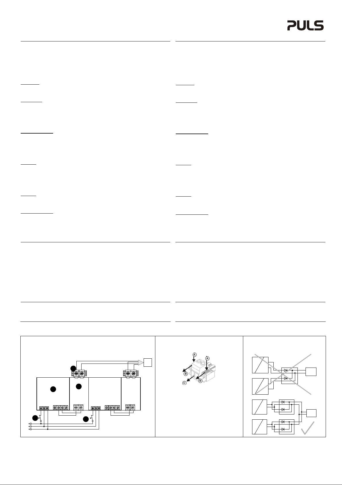
Hot-Swap Feature of the YR40.245 (see Fig. 1 and 2)
The output of the YR40.245 is equipped with a plug-connector, which allows replacing the power
supply or the redundancy module while the system is running (hot swapping).
Instructions:
- Switch-off circuit breaker (3a).
- Remove plug (4). The plug prevents the cables from shorting.
- Change power supply (1) or/ and redundancy module (2).
- Put the plug (4) back in.
- Turn-on the circuit breaker (3a).
- The circuit is redundant again.
To replace the right power supply or redundancy module, use the same procedure but turn off
circuit breaker (3b).
Utilizing the YR2.DIODE redundancy module with voltages above 60Vdc
The YR2.DIODE redundancy module can be used with input voltages up to 150Vdc with the
constraint, that it can be used only as a single input module at voltages above 60Vdc. Both inputs
need to be connected together as shown in Figure 3.
Replacing the power supply or the redundancy module while the system is running/
Tausch eines Netzgeräts oder Redundanzmoduls während eines laufenden Systems
Power Supply
3a
I I
L
N
PE
Fig. 1 / Bild 1 YR40.245 Hot swapping:
4
+
-
Output
2
YRH40.245
Redundancy
Module
Input
+
-
- -
L N PE
1
DC 24V
+ +
3b
Power Supply
L N PE
+ +
DC 24V
Load
+
-
Output
YRH40.245
Redundancy
Module
Input
+
-
- -
Anschlussklemmen und Verdrahtung
Verwenden Sie Kupferkabel, die für folgende Mindest- Betriebstem p er atur zug el assen sind :
60°C bei Umgebungstemperaturen bis zu 45°C und 75°C bei Umgebungstemperaturen bis zu
60°C und 90°C bei Umgebungstemperaturen bis zu 70°C. Beachten Sie nationale Bestimmungen
und Installationsvorschriften! Stellen Sie sicher, dass keine einzelnen Drähte von Litzen abstehen.
Bis zu zwei Leiter mit gleichem Querschnitt sind in einem Anschlusspunkt erlaubt. Aderendhülsen
sind erlaubt, aber nicht erforderlich. Nichtbenutzte Klemmen zudrehen, um die GL Schock- und
Vibrationsanforderungen zu erfüllen. Die externe Beschaltung aller Klemmen (einschließlich
Signalklemmen) muss den Anforderungen an SELV Kreisen nach IEC/EN/UL 60950-1 genügen.
YR2.DIODE
Eingang- und Ausgangsklemmen (Federkraftklemme):
Starrdraht / Litze / AWG 0,5-6mm2 / 0,5-4mm2 / 20-10 AWG
Abisolierlänge 10mm / 0,4inch
YRM2.DIODE
Eingang- und Ausgangsklemmen (Schraubklemme):
Starrdraht / Litze / AWG 0,5-6mm2 / 0,5-4mm2 / 20-10 AWG
Abisolierlänge / Anzugsdrehmoment 7mm / 0,28inch / 0,8Nm / 7lb.inch
Signalklemmen (Steckverbinder mit Schraubklemme):
Starrdraht / Litze / AWG 0,2-1,5mm2 / 0,2-1,5mm2 / 22-14 AWG
Abisolierlänge / Anzugsdrehmoment 6mm / 0,25inch / 0,4Nm / 3,5lb.inch
YR40.241, YR40.242
Eingangsklemmen (Schraubklemme):
Starrdraht / Litze / AWG 0,5-6mm2 / 0,5-4mm2 / 20-10 AWG
Abisolierlänge / Anzugsdrehmoment 7mm / 0,28inch / 0,8Nm / 7lb.inch
Ausgangsklemmen (Schraubklemme):
Starrdraht / Litze / AWG 0,5-16mm2 / 0,5-10mm2 / 22-8 AWG
Abisolierlänge / Anzugsdrehmoment 12mm / 0,5inch / 1,2Nm / 10,6lb.inch
YR40.245
Eingangsklemmen (Schraubklemme):
Starrdraht / Litze / AWG 0,5-16mm2 / 0,5-10mm2 / 22-8 AWG
Abisolierlänge / Anzugsdrehmoment 12mm / 0,5inch / 1,2Nm / 10,6lb.inch
Ausgangsklemmen (steckbare Schraubklemme):
Starrdraht / Litze / AWG 0,2-16mm2 / 0,5-10mm2 / 22-6 AWG
Abisolierlänge / Anzugsdrehmoment 12mm / 0,5inch / 1,4Nm / 12lb.inch
YR40.482
Eingang- und Ausgangsklemmen (Schraubklemme):
Starrdraht / Litze / AWG 0,5-16mm2 / 0,5-10mm2 / 22-8 AWG
Abisolierlänge / Anzugsdrehmoment 12mm / 0,5inch / 1,2Nm / 10,6lb.inch
YR80.241, YR80.242
Eingangsklemmen (Schraubklemme):
Starrdraht / Litze / AWG 0,5-16mm2 / 0,5-10mm2 / 22-8 AWG
Abisolierlänge / Anzugsdrehmoment 12mm / 0,5inch / 1,2Nm / 10,6lb.inch
Ausgangsklemmen (Schraubklemme):
Starrdraht / Litze / AWG 0,5-35mm2 / 0,5-35mm2 / 20-2 AWG
Abisolierlänge / Anzugsdrehmoment 18mm / 0,7inch / 2,5Nm / 22lb.inch
„Hot-Swap“ Eigenschaft des YR40.245 (siehe Bilder 1 und 2)
Der Ausgang des YR40.245 ist mit einem Steckverbinder ausgestattet und ermöglicht das
Austauschen der Stromversorgung oder des Redundanzmoduls während eines laufenden
Systems („hot swapping“).
Anleitung:
- Sicherung oder Schutzschalter (3a) öffnen.
- Steckverbinder (4) abziehen.
Der Steckverbinder verhindert, dass die Kabelenden einen Kurzschluss verursachen können.
- Nun kann die Stromversorgung (1) und/ oder das Redundanzmodul (2) ausgetauscht werden.
- Steckverbinder (4) wieder einstecken.
- Sicherung oder Schutzschalter (3a) wieder schließen.
- Redundanz ist wieder hergestellt.
Mit der selben Prozedur können auch die rechts angeordnete Stromversorgung oder das
Redundanzmodul getauscht werden, wenn Sicherung oder Schutzschalter (3b) geöffnet wird.
Verwendung des YR2.DIODE Redundanzmodul mit Spannungen größer 60Vdc
Das YR2.DIODE Redundanzmodul kann mit Eingansspannungen bis zu 150Vdc verwendet
werden. Über 60Vdc darf das Modul jedoch nur als Einfachmodul verwendet werden. Beide
Eingänge müssen parallel verschaltet werden wie es in Bild 3 gezeigt ist.
Fig. 2 / Bild 2 YR40.245:
Plug-connector/
Steckverbinder
Instructions for removing the plug connector:
A: Unlock the red sliders by pushing the tabs down
B: At the same time sli de the tabs back
C: Pull-out to the connector
To insert the plug connector, reverse the procedure.
Anleitung zum Lösen des Steckverbinders:
A: Zum Lösen des Verriegelungsmechanismus beide
roten Schieber nach unten drücken
B: In gedrückter Stellung nach hinten schieben
C: Stecker abziehen
Umgekehrte Prozedur zum Einstecken und Verriegeln
des Steckverbinders.
Fig. 3 / Bild 3 YR2.DIODE:
Utilizing voltages between 60 and 150Vdc/
Betrieb mit Spannungen zwischen 60 und 150Vdc
Power Supply
AC
+
Diode Module
-
+
+
+
DC
(>60V)
Power Supply
AC
DC
(>60V)
Power Supply Diode Module
AC
+
-
DC
(>60V)
Power Supply
AC
+
-
DC
(>60V)
-
+
-
+
-
+-+
+
-
Diode Module
+-+
+
-
Load
-
-
>60V
-
+
Load
-
>60V
-
Page 6

YR: Redundancy Modules Instruction Manual
YR: Bedienungsanleitung für Redundanzmodule
Fig. 4 / Bild 4 YR2.DIODE: Dimensions / Abmessungen (mm) Fig. 5 / Bild 5 YRM2.DIODE: Dimensions / Abmessungen (mm)
Fig. 6 / Bild 6 YR40.241: Dimensions / Abmessungen (mm) Fig. 7 / Bild 7 YR40.242: Dimensions / Abmessungen (mm)
Fig. 8 / Bild 8 YR40.245: Dimensions / Abmessungen (mm) Fig. 9 / Bild 9 YR40.482: Dimensions / Abmessungen (mm)
PU-361.013.00-10A
Fig. 10 / Bild 10 YR80.241: Dimensions / Abmessungen (mm) Fig. 11 / Bild 11 YR80.242: Dimensions / Abmessungen (mm)
 Loading...