

Page 1
YR2.DIODE
Decoupling Module
20A
• Dual input, single output
• Two diodes with common cathode
• Rugged metal housing
• Width only 32mm
• Cost effective solution to build redundant systems
• 10-60V Wide-range input
• 20A Continuous output current
• Easy wiring;
Distribution terminals for negative pole included
• Quick-connect Spring Clamp Terminals
• 3 Year Warranty
The YR2.Diode is a decoupling module, which can be used for various purposes. The most popular applications
are redundant power source systems and separation of sensitive loads from non-sensitive loads, which can
distort the power quality of the 24V bus and causes controller failures.
Short-form Data Approvals
Input 1 DC 10-60V, 0-20A continuous operation
DC 10-60V, 0-30A for 4s
Input 2
DC 10-60V, 0-30A for 4s
Output 0-20A continuous operation
0-30A for 4s
Voltage drop 0.9V V
Peak current 150A for 10ms each input
Reverse current < 2mA each input
Dimensions 32 x 124 x 102mm width x height x depth
Ensure that the continuous output current does not exceed 25A.
Check the short-circuit current of the power sources and if the power source
can deliver more than 25A, use an appropriate fuse on the output.
DC 10-60V, 0-20A
continuous operation
- V
IN
OUT
E 246877 HazLoc
Class I Div 2, T4
Groups A,B,C,D
IND. CONT. EQ.
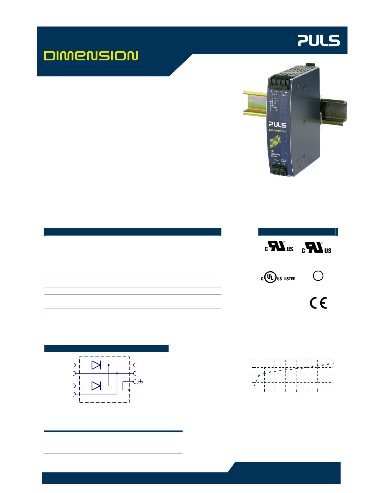
Functional Diagram Input to output voltage drop (typ.)
+
V
1
IN
-
+
2
V
IN
-
+
-
V
OUT
Chassis
Ground
1,1V
V
Drop
0,9V
0,7V
0,5V
0,3V
0A 4A 8A 12A 16A 20A 24A 28A
Order Numbers
Power Supply YR2.DIODE Decoupling Module 20A
Accessory ZM1.WALL Wall Mounting Bracket
All parameters not specifically mentioned are defined full load and 25°C ambient.
In the intrest of product improvement, specifications are subject to change without notice
1/6
DS-YR2.DIODE-EN 2005-05-03
www.pulspower.com
18WM
Output Current
137006
I.T.E. Level 5
GL
Lloyd
EMC, LVD
Germanischer
E
Page 2
YR2.DIODE
Environment
Operational temperature -25 to +70°C De-rate above 60°C
Output de-rating 0.5A/°C 60-70°C
Storage temperature -40...+85°C Storage, transport
Humidity
Vibration sinusoidal
Vibration random 0.5m2(s3) IEC 60068-2-64
Shock
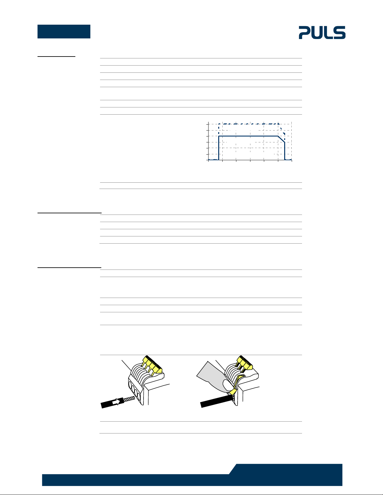
Allowed output current
versus the ambient
temperature
5...95% r.H. No condensation allowed
2-17.8Hz ±1.6mm;
17.8-500Hz 2g
15g 6ms, 10g 11ms IEC 60068-2-27
150%
125%
IEC 60068-2-6
For typ. 4s
100%
75%
Continuous
50%
25%
0%
Ambient temperature
-40°C -20°C 0°C 20°C 40°C 60°C 80°C
Ambient temperature is defined 2cm below the unit.
The unit does not release any silicone and is suitable for the use in paint shops.
Safety and Protection
Terminals and Wiring
Degree of protection IP 20 EN/IEC 60529
Class of protection II PE (Ground) connection not required
Degree of pollution 2 EN 50178, not conductive
Isolation 500Vac Input to housing (chassis ground)
Type Quick-connect spring clamp terminals
Solid wire 0.5-6mm2
Stranded wire 0.5-4mm2
AWG 20-10AWG
Ferrules Allowed, but not required
Wire stripping length 10mm / 0.4inch
Pull-out force
Use appropriate copper cables, that are designed for an operating temperature of
60°C (for ambient up to 45°C) and 75°C (for ambient up to 60°C) minimum.
Follow national installation codes and regulations! Ensure that all strands of a
stranded wire enter the terminal connection! Up to two stranded wires with the
same cross section are permitted in one connection point.
10AWG:80N, 12AWG:60N, 14AWG:50N, 16AWG:40N
(UL486E)
1. Insert the wire
To disconnect wire: same procedure vice versa
2. Snap the lever
All parameters not specifically mentioned are defined full load and 25°C ambient.
In the intrest of product improvement, specifications are subject to change without notice
2/6
DS-YR2.DIODE-EN 2005-05-03
www.pulspower.com
Page 3

YR2.DIODE
EMC
EMC Immunity EN 61000-6-1 and EN 61000-6-2
EMC Emission
This device complies with Part 15 FCC Rules. Operation is subjected to following two conditions: (1)
The Decoupling Module is suitable for applications in industrial environment as well as in residential,
commercial and light industry environment without any restrictions.
CE mark according to EMC Directive 89/336/EEC and 93/68/EEC.
Electrostatic discharge
EN 61000-4-2
Electromagnetic RF field
EN 61000-4-3
Fast transients (Burst)
EN 61000-4-4
Conducted disturbance
EN 61000-4-6
Criterion A Device shows normal operation behavior within the defined limits.
EN 61000-6-3 and EN 61000-6-4
Conducted emission input lines
EN 55011, EN 55022, FCC Part 15, CISPR 11, CISPR 22
Conducted emission output lines
EN 55022
Radiated emission
EN 55011, EN 55022
this device may not cause harmful interference, and (2) this device must accept any interference
received, including interference that may cause undesired operation.
Contact discharge
Air discharge
80MHz-1GHz 10V/m Criterion A
Input lines
Output lines
0.15-80MHz 10V/m Criterion A
8kV
15kV
4kV
2kV
Criterion A
Criterion A
Criterion A
Criterion A
Class B
Class B
(Independent of wire length)
Class B
Reliability
Approvals
Fulfilled Standards
Lifetime expectancy > 20 years 2x10A, 40degC
MTBF SN 29500, IEC 61709 46.5 Mio h 2x10A, 40degC
MTBF SN 29500, IEC 61709 70 Mio h 2x10A, 25degC
MTBF MIL HDBK 217F GF40 10 Mio h 2x10A, 40degC
MTBF MIL HDBK 217F GF25 12.7 Mio h 2x10A, 25degC
UL 508 LISTED E198865
UL 60950-1 RECOGNIZED E137006
UL 1604
Pending
The unit is suitable for use in Class I Division 2 Groups A, B, C, D locations.
Substitution of components may impair suitability for Class I Division 2
environment. Do not disconnect equipment unless power has been switched
off. Wiring must be in accordance with Class I, Division 2 wiring methods of
the National Electrical Code, NFPA 70.
Marine
Pending
IEC 60950-1 Information Technology Equipment
EN/IEC 60204-1 Safety of Electrical Equipment of Machines
EN/IEC 61131 Programmable Controllers
EN 50178 Electronic Equipment in Power Installations
Industrial Control Equipment
Information Technology Equipment Level 5
RECOGNIZED E246877
Class I Div 2 Hazardous Location
GL (Germanischer Lloyd) classified and ABS
(American Bureau for Shipping) PDA for
marine and offshore applications.
No electrolytic capacitors involved
GL
18WM
IND. CONT. EQ.
ABS
All parameters not specifically mentioned are defined full load and 25°C ambient.
In the intrest of product improvement, specifications are subject to change without notice
3/6
DS-YR2.DIODE-EN 2005-05-03
www.pulspower.com
Page 4

YR2.DIODE
Application Notes
Recommendations
for redundant
applications:
1+1 Redundancy
up to 10A output current
Utilization of two 10A
power supplies and one
YR2.DIODE.
• Use separate input fuse for each power supply.
• Use Three-phase power supplies to gain functional safety if one
phase fails.
• When Single-phase power supplies are utilized connect them to
different phases or circuits.
• It is desirable to set the output voltages of all power supplies to
the same value to avoid a false signal of the DC-ok signal.
• Use both inputs in parallel for currents above 10A.
Failure
Monitor
+ +
24V/10A
QS10.241
Power
Supply
L N PE
- -
DCok
Overload
Adj
+ +
24V/10A
QS10.241
Power
Supply
L N PE
- -
DCok
Overload
+
-
+
-
IN 1
Adj
IN 2
YR2.100
Decoupling
Module
OUT
+
-
1+1 Redundancy
up to 20A output current
Utilization of two 20A
power supplies and two
times the YR2.DIODE.
N+1 Redundancy
Example: 20A output
current
Utilization of three 10A
power supplies and two
YR2.DIODE.
The DC-ok will only work
properly if the adjusted
output voltage of each
power supply will be
reached after turning-on
the input power. A power
supply operating in current
limiting mode will result in
a DC-fail condition.
Read notes in the
individual power supply
datasheets.
+ +
24V/10A
QS10.241
Power
Supply
L N PE
I I
L
N
PE
L1
L2
L3
PE
- -
DCok
Overload
PE
Adj
L1
L2
N
+ +
24V/20A
QT20.241
Power
Supply
L1 L2 L3 PE
I I I
I I
+
- -
DCok
Overload
L N PE
YR2.100
Decoupling
Module
Adj
-
IN 1
OUT
+
- -
Overload
Adj
DCok
+ +
24V/10A
QS10.241
Power
Supply
-
+
-
IN 2
optional
+
-
IN 1
YR2.100
Decoupling
Module
OUT
+
- -
+ +
24V/20A
QT20.241
Power
Supply
L1 L2 L3 PE
I I I
+
-
IN 2
-
optional
DCok
Overload
Adj
optional
+ +
24V/10A
QS10.241
Power
Supply
L N PE
I
- -
DCok
Overload
+
IN 1
YR2.100
Decoupling
Module
OUT
+
Adj
-
+
IN 2
-
optional
-
10A
Load
Failure
Monitor
Load
+
-
IN 1
YR2.100
Decoupling
Module
OUT
+
-
20A
+
-
IN 2
Failure
Monitor
20A
Load
All parameters not specifically mentioned are defined full load and 25°C ambient.
In the intrest of product improvement, specifications are subject to change without notice
4/6
DS-YR2.DIODE-EN 2005-05-03
www.pulspower.com
Page 5

YR2.DIODE
Battery backup
10A output current:
Set output voltage of
power supply to 26.5Vdc
minimum to avoid that the
charger current flows to
the load instead of
charging the battery.
Use a fuse between
battery and YR2.DIODE!
I
24V Battery
+
Battery
Charger
Failure
Monitor
-
+ +
24V/10A
QS10.241
Power
Supply
L N PE
- -
DCok
Overload
+
-
+
-
IN 1
Adj
IN 2
YR2.100
Decoupling
Module
OUT
+
-
L
N
PE
optional
10A
Load
Redundancy for
sensitive loads
Cost effective solution to
get redundant power for a
PLC or other controller.
Standard design:
LoadPS1
PS2
PLC
Improved approach:
YR2
Load
PLC
PS1
PS2
Decoupling of
buffered branches
Buffer energy supplied
from a DC-UPS or Buffer
Module is not wasted in
“power branches”.
Set output voltage of the
power supply to a level
that the buffer unit or DCUPS will not start
unexpected. Take the
voltage drop of the
YR2.DIODE into account.
Failure
Monitor
Failure
Monitor
L1
L2
L3
N
PE
L1
L2
L3
PE
+ +
- -
24V/20A
QT20.241
Power
Supply
L1 L2 L3 PE
I I I
+ +
- -
24V/20A
QT20.241
Power
Supply
L1 L2 L3 PE
I I I
DCok
Overload
DCok
Overload
Heavy
Loads
e.g. Motors
- -
+
Adj
IN 1
YR2.100
Decoupling
Module
OUT
+
+ +
-
+
-
IN 2
24V
Adj
5A
DCok
Overload
QS5.241
Power
Supply
L N PE
-
Sensitive
Load
e.g.
optional
I
Controller
Load
e.g. Motor
+
-
+
-
IN 1
Adj
IN 2
YR2.100
Decoupling
Module
OUT
+
-
optional
DCUPS
+
-
Buffered
Load
e.g.
Controller
All parameters not specifically mentioned are defined full load and 25°C ambient.
In the intrest of product improvement, specifications are subject to change without notice
5/6
DS-YR2.DIODE-EN 2005-05-03
www.pulspower.com
Page 6

YR2.DIODE
Dimensions
Width 32mm / 1.26’’
Height 124mm / 4.88’’
Depth 102mm / 4.02’’ Plus DIN-rail depth
Weight 290g / 0.64lb
DIN-Rail
Use DIN-rails according to EN 60715 or EN 50022
with a height of 7.5 or 15mm
Accessory
Mounting Orientation
Input terminal on top and output terminals on the
bottom. For other orientations consult factory.
Cooling Convection cooled, no fan required.
Do not obstruct air flow!
Keep installation clearances when loaded with full power:
60mm on top and on the bottom,
15mm on the left and right side
ZM1.WALL Wall Mounting Bracket
5.1
133
143
4.8
32
22.5
+-+
IN
1
OUT
-
+
IN
-
2
Germany, PULS in Munich +49 89 9278 0 www.pulspower.com
China, PULS in Shanghai +86 21 6432 7680 www.puls-power.cn
France, PULS in Limonest/Lyon +33 608 5494 60 www.puls-power.com/fr
North America, PULS in St. Charles/Chicago +1 630 587 9780 www.puls-power.us
Austria, PULS in Rohrbach +43 2764 3213 www.pulspower.com
Switzerland, PULS in Oberflachs /Aargau +41 56 450 18 10 www.puls-power.ch
United Kingdom, PULS in Bedfordshire +44 1525 720099 www.puls.co.uk
Headquarter:
PULS Elektronische
Stromversorgungen
GmbH
Arabellastrasse 15
D-81925 Munich
Germany
 Loading...