

Page 1
Q.
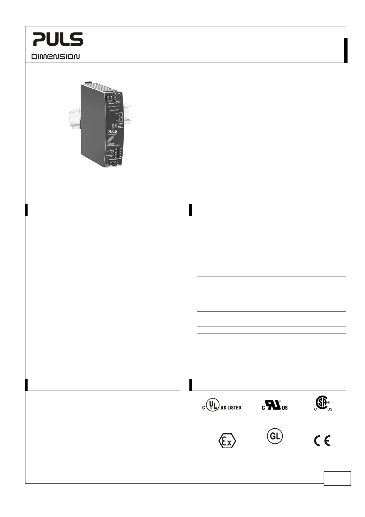
YR20.246
Y-Series
GENERAL DESCRIPTION
The YR20.246 is a redundancy module for building
redundant power supply systems. It is equipped with
two input channels and one output. The two inputs are
decoupled by MOSFET technology.
The device is equipped with an automated load sharing
feature, which can compensate a small voltage
imbalance between the power supplies connected to
the inputs in order to achieve an even current share. It
also monitors the function of the redundancy circuitry
and provides a signal in case of a failure or a high
output current, which could prevent redundancy if one
power supply fails. If this feature is not required the
YR20.242 is available.
The redundancy utilizes MOSFETs instead of diodes for
the decoupling of the two input channels. This reduces
the heat generation and the voltage drop between
input and output. The redundancy module does not
require an additional auxiliary voltage.
Due to the low power losses, the unit is very slender and
only requires 32mm width on the DIN-rail. Large
connection terminals allow for a safe and fast
installation. The large international approval package
makes this unit suitable for nearly every application.
ORDER NUMBERS
Redundancy YR20.246
Module
Accessory ZM11.SIDE Side mount bracket
24-28V, 20A, DUAL REDUNDANCY MODULE
MOSFET REDUNDANCY MODULE
For 1+1 Redundancy with Automated Load Sharing
Dual Input with Single Output
Redundancy OK Signal Included which Reports the Loss
of Redundancy
160% (32.5A) Peak Load Capability
Reverse Input Polarity Protection
Full Power Between -40°C and +70°C
Width only 32mm
Rugged Metal Housing
Easy Wiring:
Distribution Terminal for Negative Pole Included
SHORT-FORM DATA
Input voltage DC 24-28V ±25%
Input voltage range 18-35Vdc
Input current 2x 0-12A ambient <+45°C
2x 0-10A ambient <+70°C
Output current 0-24A ambient <+45°C
0-20A ambient <+70°C
Input to output
voltage drop
max. 26A
0.1-0.5V
0.2-0.5V
**)
**)
in overload
short circuit mode
input: 2x5A
input: 2x10A
*)
or
Power losses 1.7W at no load
2.6-4.7W
5.6-8.7W
**)
input: 2x5A
**)
input: 2x10A
Temperature range -40°C to +70°C operational
Dimensions 32x124x117mm WxHxD
Weight 310g, 0.69lb
*) Currents at voltages below 6V
**) Depending on load share function
MARKINGS
IND. CONT. E
UL 508
UL 60950-1
Class I Div 2
planned
IECEx ATEX
Jul. 2017 / Rev. 1.4 DS-YR20.246-EN All parameters are typical values specified at 24V, 20A output current, 25°C ambient and
after a 5 minutes run-in time unless otherwise noted.
Marine
planned
1/19
Page 2
YR20.246
Y-Series
24-28V, 20A, DUAL REDUNDANCY MODULE
INDEX
Page Page
1.
Intended Use .......................................................3
2. Installation Requirements...................................3
3. Input and Output Characteristics .......................4
4. Power Losses........................................................5
5. Lifetime Expectancy and MTBF...........................5
6. Terminals and Wiring..........................................6
7. Functional Diagram.............................................6
8. Front Side and User Elements.............................7
9. “Redundancy OK” Relay Contact.......................8
10. “Load Share OK” Relay Contact .........................8
11. Automated Load Sharing....................................9
12. EMC....................................................................10
13. Environment ......................................................11
14. Protection Features ...........................................12
15. Safety Features ..................................................12
The information given in this document is correct to the best of our knowledge and experience at the time of publication. If not
expressly agreed otherwise, this information does not represent a warranty in the legal sense of the word. As the state of our
knowledge and experience is constantly changing, the information in this data sheet is subject to revision. We therefore kindly ask
you to always use the latest issue of this document (available under www.pulspower.com). No part of this document may be
reproduced or utilized in any form without our prior permission in writing.
16. Dielectric Strength............................................ 12
17. Approvals.......................................................... 13
18. RoHS, REACH and Other Fulfilled Standards .. 13
19. Physical Dimensions and Weight ..................... 14
20. Accessories ........................................................ 15
20.1. ZM11.SIDE - Side Mounting Bracket........15
21. Application Notes............................................. 16
21.1. Using Only One Input Instead of Both
Channels...............................................................16
21.2. Recommendations for Redundancy.........17
21.3. Inductive and Capacitive Loads................17
21.4. Sidewards Installation Clearances............17
21.5. 1+1 Redundancy up to 10A...................... 18
21.6. Mounting Orientations ............................19
TERMINOLOGY AND ABREVIATIONS
DC 24V A figure displayed with the AC or DC before the value represents a nominal voltage with
standard tolerances (usually ±15%) included.
E.g.: DC 12V describes a 12V battery disregarding whether it is full (13.7V) or flat (10V)
24Vdc A figure with the unit (Vdc) at the end is a momentary figure without any additional
tolerances included.
may A key word indicating flexibility of choice with no implied preference
shall A key word indicating a mandatory requirement
should A key word indicating flexibility of choice with a strongly preferred implementation
1+1 Redundancy Use of two identical power supplies in parallel to provide continued
operation following most failures in a single power supply. The two power
supply outputs should be isolated from each other by utilizing diodes or
other switching arrangements. E.g. two 10A power supplies are needed to
achieve a 10A redundant system.
ACDCAC
IN 1
IN 2
OUT
+
Load
-
DC
Jul. 2017 / Rev. 1.4 DS-YR20.246-EN All parameters are typical values specified at 24V, 20A output current, 25°C ambient and
after a 5 minutes run-in time unless otherwise noted.
2/19
Page 3
YR20.246
Y-Series
24-28V, 20A, DUAL REDUNDANCY MODULE
1. INTENDED USE
This redundancy module is designed for installation in an enclosure and is intended for the general use such as in
industrial control, office, communication, and instrumentation equipment.
This redundancy module can be used with any type of power supply as long as the maximum output current ratings
are not exceeded. It is suitable for power supplies with constant current overload behavior as well as any kind of
“Hiccup” overload behavior.
Do not use this redundancy module in equipment, where malfunction may cause severe personal injury or threaten
human life.
2. INSTALLATION REQUIREMENTS
This device may only be installed and put into operation by qualified personnel.
This device does not contain serviceable parts.
If damage or malfunction should occur during installation or operation, immediately turn power off and send unit to
the factory for inspection.
To ensure a proper load share function ensure that the wiring between the two power supplies and the redundancy
module is identical.
Mount the unit on a DIN-rail so that the input terminals are located on the bottom and the output terminals on the
top of the unit. For other mounting orientations see de-rating requirements of chapter 21.6 in this document.
This device is designed for convection cooling and does not require an external fan. Do not obstruct airflow and do
not cover the ventilation grid (e.g. cable conduits) by more than 30%!
Keep the following installation clearances:
40mm on top,
20mm on the bottom,
5mm on the left and right sides are recommended when the device is loaded permanently with more than 50% of the
rated output current. Increase the side clearance to 15mm in case the adjacent device is a heat source (e.g. another
power supply). See chapter 21.4 for other allowed clearances when used with the PULS DIMENSION series in a 1+1
redundant configuration.
Use only power supplies with a negligible output ripple voltage in the low frequency range between 50Hz and 10kHz
when used in marine applications according to the GL regulations.
The input must be powered from a SELV source (according to IEC 60950-1), a PELV source (according to IEC 62477-1) or
an Isolated Secondary Circuit (according to UL 508).
Do not ground or earth the positive output pole which could prevent redundancy in case of a ground failure. Ground
the negative output pole when needed.
WARNING
- Turn power off before working on the device. Protect against inadvertent re-powering.
- Make sure that the wiring is correct by following all local and national codes.
- Do not open, modify or repair the unit.
- Use caution to prevent any foreign objects from entering the housing.
- Do not use in wet locations or in areas where moisture or condensation can be expected.
- Do not touch during power-on, and immediately after power-off. Hot surfaces may cause burns.
Risk of electrical shock, fire, personal injury or death.
Jul. 2017 / Rev. 1.4 DS-YR20.246-EN All parameters are typical values specified at 24V, 20A output current, 25°C ambient and
after a 5 minutes run-in time unless otherwise noted.
3/19
Page 4
YR20.246
Y-Series
24-28V, 20A, DUAL REDUNDANCY MODULE
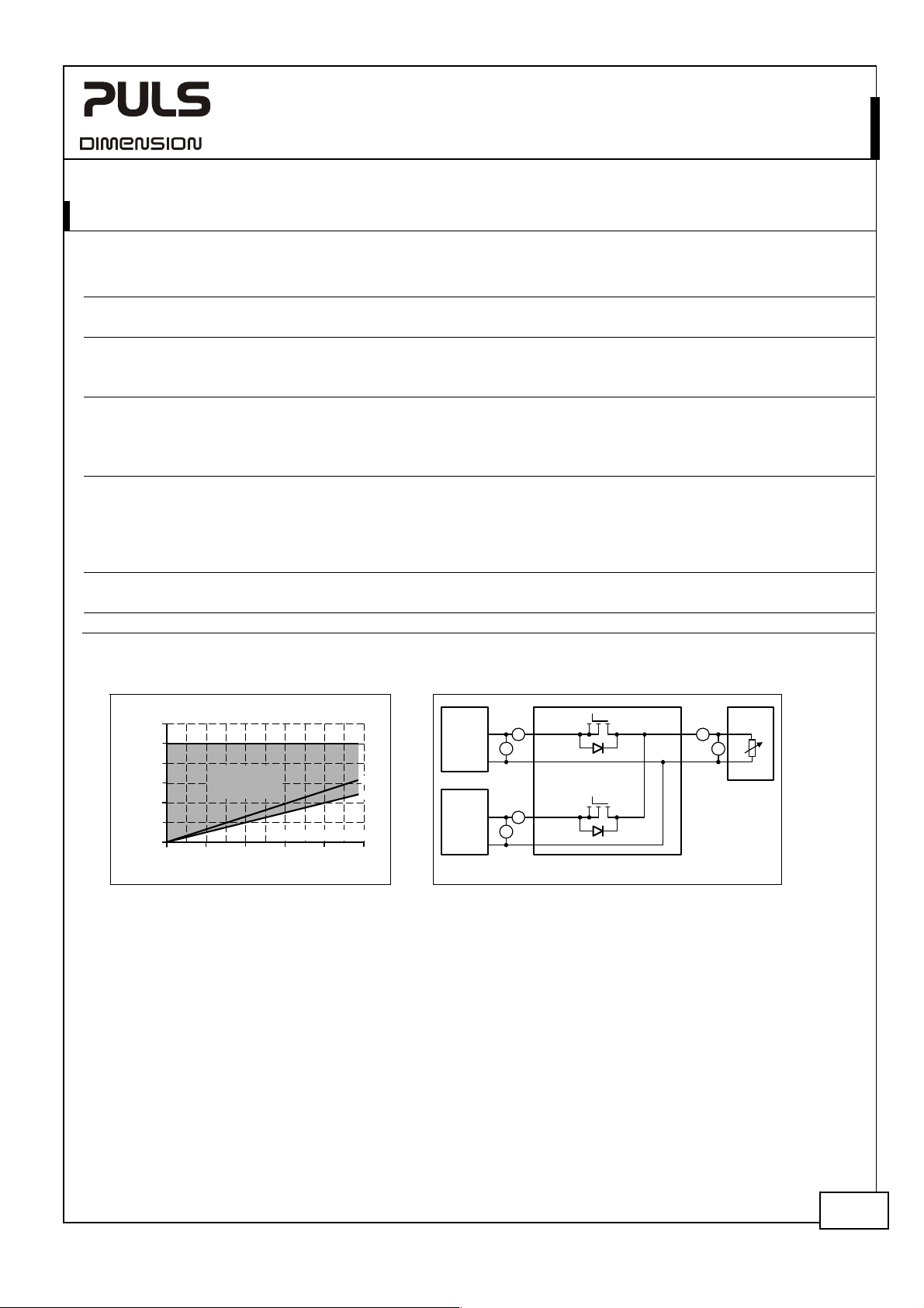
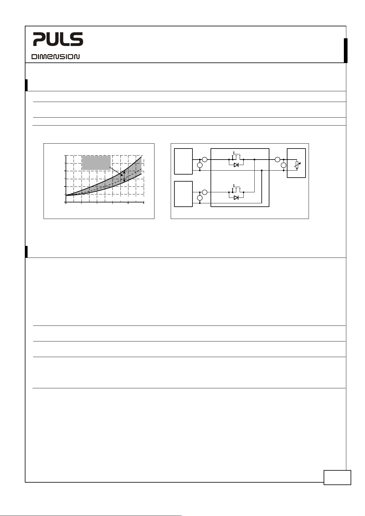
3. INPUT AND OUTPUT CHARACTERISTICS
Number of inputs - 2
Number of outputs - 1
Input voltage nom. DC 24-28V ±25%
Input voltage range - 18-35Vdc
Voltage drop, input to output typ. 0.1-0.5V at 2x5A, load share function dependent, see Fig. 3-1
typ. 0.2-0.5V at 2x10A, load share function dependent, see Fig. 3-1
typ. 0.24-0.5V at 2x12A, load share function dependent, see Fig. 3-1
Input current nom. 2x 0-12A continuous, ambient temperature < +45°C
nom. 2x 0-10A continuous, ambient temperature < +70°C
nom. 2x 17A
max. 2x 700A for max. 1ms
Output current nom. 24A continuous, ambient temperature < +45°C
nom. 20A continuous, ambient temperature < +70°C
nom. 32.5A for max. 5 seconds
max. 26A in overload /short-circuit (voltage < 6V). Ensure that the
Reverse current max. 1mA at 24V, per input, -40°C to +70°C
Reverse voltage max. 40Vdc voltage applied to the output, continuously allowed
Output capacitance typ. 320μF
1) The average value (R.M.S. value) of the output current must not exceed the values of the continuous output current.
Fig. 3-1 Input to output voltage drop Fig. 3-2 Test setup for voltage drop measurements
Voltage Drop, typ
600mV
500mV
400mV
300mV
200mV
100mV
0mV
Output:
Input:
0
0
Depending on
Load Share
Regulation
Input / Output Current
5A 15A
2x5A2x2.5A
60°C
25°C
25A
20A10A
2x10A2x7.5A
2x12.5A
1)
for max. 5 seconds
sum of input currents does not exceed this value.
Power
Supply
+
24V, 12A
-
Power
Supply
+
24V, 12A
-
I1I2=
YR20.246
I
1
A
Input 1
V
U
1
I
2
A
Input 2
V
U
2
U2U1= Voltage Drop
Output
Output
I
OUT
A
U
OUT
V
Variable
Load,
0-24A
U1=
U
-
OUT
Jul. 2017 / Rev. 1.4 DS-YR20.246-EN All parameters are typical values specified at 24V, 20A output current, 25°C ambient and
after a 5 minutes run-in time unless otherwise noted.
4/19
Page 5
YR20.246
Y-Series
24-28V, 20A, DUAL REDUNDANCY MODULE
4. POWER LOSSES
Power losses typ.
typ.
2.6-4.7W
5.6-8.7W
Standby power losses typ. 1.7W at no output current
Fig. 4-1 Power losses Fig. 4-2 Test setup for power loss measurements
Power Losses, typ
12W
10W
8W
6W
4W
2W
Output:
Input:
25/
20A10A
60°C
60°C
25°C
25A
2x12.5A
Depending on
Load Share
Regulation
2x5A2x2.5A
Input / Output Current
2x10A2x7.5A
0
5A 15A
0
0
Power
Supply
+
24V, 12A
Power
Supply
24V, 12A
I1I2=
V
-
+
V
-
at 2x5A, 25°C ambient temperature
at 2x10A, 25°C ambient temperature
YR20.246
I
1
A
Input 1
U
1
I
2
A
Input 2
U
2
U2U1=Losses
U1=
Output
I1+)(
*
U
2
Output
I
OUT
A
U
OUT
I
2
*
Variable
Load,
0-24A
V
U
OUT
-
I
OUT
*
5. LIFETIME EXPECTANCY AND MTBF
The redundancy module has two input channels which are completely independent from each other. Each control
circuit, auxiliary voltage source, or other circuitry in the module are designed separately for each input. The dual input
redundancy module can be considered as two single redundancy modules combined together in one housing. The only
common point is the circuit trace that ties the two separate circuits together at the output.
The MTBF figures below are for the entire dual input module. If the MTBF number of only one path is needed, simply
double the value from the table.
Input / output current
conditions
*)
Lifetime expectancy
372 000h
1 053 000h
**)
MTBF
SN 29500, IEC 61709 2 306 000h 1 954 000h at 24V and 40°C
Input: 2x5A
Output: 10A
*)
182 000h
*)
Input: 2x10A
Output: 20A
516 000h
*)
at 24V and 40°C
*)
at 24V and 25°C
3 913 000h 3 359 000h at 24V and 25°C
**)
MTBF
MIL HDBK 217F 964 000h 858 000h Ground Fixed GF40 (24V and 40°C)
1 379 000h 1 226 000h Ground Fixed GF25 (24V and 25°C)
278 000h 243 000h Ground Benign GB40 (24V and 40°C)
381 000h 330 000h Ground Benign GB25 (24V and 25°C)
*) The Lifetime expectancy shown in the table indicates the minimum operating hours (service life) and is determined by the lifetime
expectancy of the built-in electrolytic capacitors. Lifetime expectancy is specified in operational hours and is calculated according to the
capacitor’s manufacturer specification. The manufacturer of the electrolytic capacitors only guarantees a maximum life of up to 15 years
(131 400h). Any number exceeding this value is a calculated theoretical lifetime which can be used to compare devices.
**) MTBF stands for Mean Time Between Failure, which is calculated according to statistical device failures, and indicates reliability of a
device. It is the statistical representation of the likelihood of a unit to fail and does not necessarily represent the life of a product.
The MTBF figure is a statistical representation of the likelihood of a device to fail. A MTBF figure of e.g. 1 000 000h means that
statistically one unit will fail every 100 hours if 10 000 units are installed in the field. However, it can not be determined if the failed unit
has been running for 50 000h or only for 100h.
Jul. 2017 / Rev. 1.4 DS-YR20.246-EN All parameters are typical values specified at 24V, 20A output current, 25°C ambient and
after a 5 minutes run-in time unless otherwise noted.
5/19
Page 6
YR20.246
Y-Series
24-28V, 20A, DUAL REDUNDANCY MODULE
6. TERMINALS AND WIRING
Type Screw termination
Solid wire max. 6mm2 max. 1.5mm2
Stranded wire max. 4mm
American Wire Gauge 20-10 AWG AWG 24-16
Max. wire diameter 2.8mm (including ferrule) max. 1.6mm (including ferrules)
Wire stripping length 7mm / 0.28inch 7mm / 0.28inch
Screwdriver 3.5mm slotted or Pozidrive No 2 not required
Recommended tightening torque 0.8Nm, 7lb.in not applicable
Instructions:
a) Use appropriate copper cables that are designed for minimum operating temperatures of:
60°C for ambient up to 45°C and
75°C for ambient up to 60°C and
90°C for ambient up to 70°C minimum.
b) Follow national installation codes and installation regulations!
c) Ensure that all strands of a stranded wire enter the terminal connection!
d) Screws of unused terminal compartments should be securely tightened.
e) Ferrules are allowed.
Input and Output Signals
Push-in terminals
IP20 Finger safe construction.
Suitable for field installation.
2
max. 1.5mm2
7. FUNCTIONAL DIAGRAM
Input
Voltages
Monitor
+
Input 1
-
+
Input 2
-
Control
Control
Fig. 7-1 Functional diagram
OK
Input 2Input 1
Load Share
Controller
Output Current
Monitor
Redundancy OK
Controller
Load Share
OK
Redundancy
OK
13
Load Share OK
Contact
14
5A
Output current
10A
alarm threshold
20A
Output current < IN
Redundancy OK
23
Redundancy OK
Contact
24
+
Output
-
Chassis
Ground
Jul. 2017 / Rev. 1.4 DS-YR20.246-EN All parameters are typical values specified at 24V, 20A output current, 25°C ambient and
after a 5 minutes run-in time unless otherwise noted.
6/19
Page 7

YR20.246
Y-Series
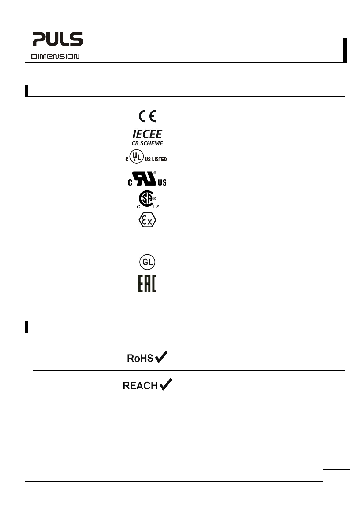
8. FRONT SIDE AND USER ELEMENTS
Fig. 8-1 Front side
Output terminals (screw terminals)
A
Chassis-Ground terminal
B
Connection of the chassis is optional and not required since the unit fulfils the
requirements according to protection class III.
Input terminals for input 1 (screw terminals)
C
D Input terminals for input 2 (screw terminals)
E Selector for output current warning threshold
If the output current increases, e. g. due to additionally loads, and exceeds the
nominal current of one power supply unit, redundancy is no longer guaranteed.
To avoid the loss in redundancy, the output current is monitored and is
reported through LEDs and relay contacts when exceeding the predefined
value.
- Set the selector to 5A in combination with two 5A power supplies (1+1 red.)
- Set the selector to 10A in combination with two 10A power supplies (1+1 red.)
- Set the selector to 20A for n+1 redundant systems. With this setting,
redundancy cannot be checked by the redundancy module any more.
Exceeding the current by less than 2 seconds will be ignored.
Green LED “Output current < IN”
F
The LED is on solid when the output current is smaller than the adjusted value
of the output current alarm selector (E).
Load share LEDs
G
The three LEDs indicate the status of the load sharing between the two power
supplies.
See chapter 11 for detailed description.
Green LED “Redundancy OK”
H
The LED is on solid when no errors are detected.
Errors:
- One or both input voltages are out of range (below 22V or above 30V).
- Output current is higher than the adjusted value of the output current
threshold setting.
- Internal defect is detected
Relay contact “Redundancy OK” (push-in terminals)
I
The relay contact is closed when no redundancy errors are detected. The relay
contact is also synchronized with the “Redundancy OK” LED.
See chapter 9 for contact ratings.
Relay contact “Load share OK” (push-in terminals)
J
The relay contact is closed when the output voltage of the two power supplies
are sufficiently adjusted.
Deviations less than 2s will be ignored.
See chapter 11 for detailed description.
See chapter 10 for contact ratings.
24-28V, 20A, DUAL REDUNDANCY MODULE
Jul. 2017 / Rev. 1.4 DS-YR20.246-EN All parameters are typical values specified at 24V, 20A output current, 25°C ambient and
after a 5 minutes run-in time unless otherwise noted.
7/19
Page 8

YR20.246
Y-Series
24-28V, 20A, DUAL REDUNDANCY MODULE
9. “REDUNDANCY OK” RELAY CONTACT
This feature reports the loss of redundancy by opening the relay contact (pin 23 and 24).
Contact is closed When no errors are detected
Contact is open When:
- one or both input voltages are below 22Vdc or above 30Vdc.
- the output current is higher than the adjusted value of the output current threshold setting.
- an internal defect of the redundancy module is detected (decoupling measures and several
internal test routines).
Input voltage errors less than 2s will be ignored.
Overcurrent errors (less than 150% of the adjusted value) less than 4s will be ignored.
Overcurrent errors (above 150% of the adjusted value) less than 30ms will be ignored.
Internal errors less than 10s will be ignored
Contact ratings max. 60Vdc 0.3A, 30Vdc 1A, 30Vac 0.5A resistive load
min. 1mA at 5Vdc minimum permissible load
Isolation voltage See dielectric strength table in section 16.
10. “LOAD SHARE OK” RELAY CONTACT
This feature monitors if the output voltages of the two power supplies connected to the input are sufficiently adjusted
for an even current distribution. The relay contact (pin 13 and 14) is closed, when load sharing occurs.
Contact is closed When the adjustment of the output voltages are sufficient
Contact is open When an even load share does not occur and readjustment of the output voltages is
recommended.
Details see chapter 11.
Contact ratings max. 60Vdc 0.3A, 30Vdc 1A, 30Vac 0.5A resistive load
min. 1mA at 5Vdc minimum permissible load
Isolation voltage See dielectric strength table in section 16.
Jul. 2017 / Rev. 1.4 DS-YR20.246-EN All parameters are typical values specified at 24V, 20A output current, 25°C ambient and
after a 5 minutes run-in time unless otherwise noted.
8/19
Page 9

YR20.246
Y-Series
24-28V, 20A, DUAL REDUNDANCY MODULE
11. AUTOMATED LOAD SHARING
Drawing even current from both power supplies in a redundancy application can provide a longer service life of the
redundant power supply system. An evenly shared current can avoid that one of the two units is getting much hotter
than the other, which reduces the lifetime of the power supply system. The YR20.246 redundancy module is equipped
with an automated load share feature, which can compensate a certain voltage unbalance between the two power
supplies connected to the inputs.
However, to reduce the losses of the active circuit in the redundancy module, the individual output voltages shall be
set as close as possible. The three LEDs on the front of the unit help to indicate if adjustment is necessary.
Optimal load sharing and
minimal power losses
Input 1
+
OK
+
Input 2
Input 1
+
OK
+
Input 2
To optimize power losses, reduce the output voltage
of the power supply, where the yellow LED is on.
Input 1
Input 2
typ. 90mV
typ. 90mV
Input 1
Input 2
Fig. 11-1 Load sharing
+
OK
+
+
OK
+
typ. 370mV
typ. 370mV
Input 1
+
OK
+
Input 2
Input 1
+
OK
+
Input 2
Reduce output voltage
of power supply 1
V
> V
OUT1
V
= V
OUT1
V
< V
OUT1
Reduce output voltage
of power supply 2
OUT2
OUT2
OUT2
Automated load sharing possible
"Load Share OK" contact is closed
Automated load sharing not possible
"Load Share OK" contact is open
The active load share feature of the YR20.246 has a similar effect and benefit as the feature “Parallel Mode” (soft
output characteristic), which is available on larger PULS power supplies.
Jul. 2017 / Rev. 1.4 DS-YR20.246-EN All parameters are typical values specified at 24V, 20A output current, 25°C ambient and
after a 5 minutes run-in time unless otherwise noted.
9/19
Page 10

YR20.246
Y-Series
24-28V, 20A, DUAL REDUNDANCY MODULE
12. EMC
The redundancy module is suitable for applications in industrial environment as well as in residential, commercial and
light industry environment without any restrictions.
EMC Immunity
Electrostatic discharge EN 61000-4-2 Contact discharge
Electromagnetic RF field EN 61000-4-3 80MHz-2.7GHz 10V/m Criterion A
Fast transients (Burst) EN 61000-4-4 Input lines
Surge voltage on input
lines
Surge voltage on output
lines
Surge voltage on signal
lines
Conducted disturbance EN 61000-4-6 0.15-80MHz 20V Criterion A
Power-frequency magnetic
field 1)
Criterions:
A: Redundancy module shows normal operation behavior within the defined limits.
Notes:
1) A test is not applicable according to EN 61000-6-2, since the device does not contain components susceptible to magnetic fields, e.g. hall
elements, electrodynamic microphones, etc.
2) Tested with capacitive coupling clamp.
EMC Emission
Conducted emission
input lines
Conducted emission
output lines
Radiated emission EN 55011, EN 55022 Class B
This device complies with FCC Part 15 rules.
Operation is subjected to following two conditions: (1) this device may not cause harmful interference, and (2) this
device must accept any interference received, including interference that may cause undesired operation.
Notes:
3) For information only, not mandatory for EN 61000-6-3.
4) Provided, that power sources connected on the inputs fulfill the requirements too.
Switching frequency
According to generic standards: EN 61000-6-1 and EN 61000-6-2
Air discharge
Output lines
Redundancy OK signal
Load share OK signal
2)
2)
EN 61000-4-5 + Æ -
+/- Æ Chassis ground
EN 61000-4-5 + Æ -
+/- Æ Chassis ground
EN 61000-4-5 Load Share OK signalÆ PE
Redundancy OK signal
8kV
15kV
2kV
2kV
2kV
2kV
500V
1kV
500V
1kV
1kV
1kV
Criterion A
Criterion A
Criterion A
Criterion A
Criterion A
Criterion A
Criterion A
Criterion A
Criterion A
Criterion A
Criterion A
Criterion A
EN 61000-4-8 50Hz 30A/m Criterion A
According to generic standards: EN 61000-6-3 and EN 61000-6-4
IEC/CISPR 16-1-2, IEC/CISPR 16-2-1 limits for DC power ports according
EN 61000-6-3 fulfilled
IEC/CISPR 16-1-2, IEC/CISPR 16-2-1 limits for DC power ports according
EN 61000-6-3 fulfilled
4)
3) 4)
3) 4)
The internal auxiliary supply is generated with a boost converter.
The switching frequency varies from 140kHz to 500kHz depending on the input voltage.
Jul. 2017 / Rev. 1.4 DS-YR20.246-EN All parameters are typical values specified at 24V, 20A output current, 25°C ambient and
after a 5 minutes run-in time unless otherwise noted.
10/19
Page 11

YR20.246
Y-Series
24-28V, 20A, DUAL REDUNDANCY MODULE
13. ENVIRONMENT
Operational temperature
Storage temperature -40 to +85°C (-40°F to 185°F) for storage and transportation
Humidity
**)
5 to 95% r.H. IEC 60068-2-30
Vibration sinusoidal
***)
Shock
30g 6ms, 20g 11ms
Altitude 0 to 2000m (0 to 6 560ft) without any restrictions
2000 to 6000m (6 560 to 20 000ft) reduce output power or ambient temperature,
Altitude de-rating 1.25A/1000m or 5°C/1000m > 2000m (6500ft), see Fig. 13-2
Over-voltage category not applicable The concept of the overvoltage category is
Degree of pollution 2 EN 62477-1, not conductive
LABS compatibility The unit does not release any silicone or other LABS-critical substances and is suitable for
*) Operational temperature is the same as the ambient temperature and is defined as the air temperature 2cm below the unit.
**) Do not energize while condensation is present
***) Tested in combination with DIN-Rails according to EN 60715 with a height of 15mm and a thickness of 1.3mm and standard mounting
orientation.
Fig. 13-1 Output current vs. ambient temp. Fig. 13-2 Output current vs. altitude
Allowed Output Current
32.5A
s
h
o
r
t
t
e
24
n
o
r
m
l
20
15
10
5
0
a
Ambient Temperature
-25
-40 0 20 45
*)
-40°C to +70°C (-40°F to 158°F)
***)
2-17.8Hz: ±1.6mm; 17.8-500Hz: 2g
2 hours / axis
3 bumps / direction, 18 bumps in total
use in paint shops.
r
m
(
s
<
5
)
o
m
d
e
70°C
IEC 60068-2-6
IEC 60068-2-27
see Fig. 13-2
used for equipment energized directly from
the low voltage mains (IEC 60664-1 §4.3.3.2.1).
Allowed Output Current
32.5A
s
h
o
r
t
t
e
r
m
(
s
<
5
)
n
o
r
m
l
a
m
o
d
24
20
15
10
A... Tamb < 45°C
5
B... Tamb < 70°C
0
0 2000 4000
e
A
B
Altitude
6000m
Jul. 2017 / Rev. 1.4 DS-YR20.246-EN All parameters are typical values specified at 24V, 20A output current, 25°C ambient and
after a 5 minutes run-in time unless otherwise noted.
11/19
Page 12

YR20.246
Y-Series
24-28V, 20A, DUAL REDUNDANCY MODULE
14. PROTECTION FEATURES
Output over-current protection not included
Reverse input polarity
protection
Degree of protection IP 20 EN/IEC 60529
Penetration protection > 3.6mm e.g. screws, small parts
Over-temperature protection not included
Input transient protection included see EMC section
Output transient protection included see EMC section
Internal input fuse not included
included unit does not start when input voltage is reversed
15. SAFETY FEATURES
Input / output separation no galvanic separation Mosfet between input and output
Safety level of output voltage The output voltage is regarded to be SELV (EN 60950-1) or PELV (EN 60204-1, EN
62477-1, IEC 60364-4-41) if the input voltage fulfills the requirements for a SELV
source or PELV source.
Class of protection III PE (Protective Earth) or chassis connection not required
PE resistance < 0.1Ohm between housing and chassis-ground terminal
16. DIELECTRIC STRENGTH
The input and output voltages have the same reference, are floating and have no ohmic connection to ground.
Type and factory tests are conducted by the manufacturer. Field tests may be conducted in the field using the
appropriate test equipment which applies the voltage with a slow ramp (2s up and 2s down). Connect input/output
and signal terminals together before conducting the test.
When testing, set the cut-off current settings to the value in the table below.
Fig. 16-1 Dielectric strength
+
-
Jul. 2017 / Rev. 1.4 DS-YR20.246-EN All parameters are typical values specified at 24V, 20A output current, 25°C ambient and
after a 5 minutes run-in time unless otherwise noted.
Load Share OK,
Redundancy OK
A
B
ChassisIn- / Output
B
Type test 60s 500Vac 500Vac
Factory test 5s 500Vac 500Vac
Field test 5s 500Vac 500Vac
Cut-off current setting > 2mA > 2mA
A B
12/19
Page 13
YR20.246
17. APPROVALS
EC Declaration of Conformity
IEC 60950-1
UL 508
UL 60950-1
ANSI / ISA 12.12.01-2007
Class I Div 2,
planned
ATEX
EN 60079-0, EN 60079-7
IECEx
IEC 60079-0, IEC 60079-7
Marine,
planned
EAC TR Registration
Y-Series
IND. CONT. EQ.
II 3G Ex ec nC IIC T4 Gc
IECEx
Ex ec nC IIC T4 Gc
24-28V, 20A, DUAL REDUNDANCY MODULE
The CE mark indicates conformance with the
- EMC directive and the
- ATEX directive.
CB Scheme,
Information Technology Equipment
Listed for use as Industrial Control Equipment;
U.S.A. (UL 508) and Canada (C22.2 No. 107-1-01);
E-File: E198865
Recognized for use as Information Technology Equipment,
Level 5; U.S.A. (UL 60950-1) and Canada (C22.2 No. 60950);
E-File: E137006
LISTED for use in Hazardous Location Class I Div 2 T4 Groups
A,B,C,D systems; U.S.A. (ANSI / ISA 12.12.01-2007) and Canada
(C22.2 No. 213-M1987)
Suitable for use in Category 3 Zone 2 locations.
Number of ATEX certificate: EPS 11 ATEX 1 312 X
The redundancy module must be built-in in an IP54 enclosure.
Suitable for use in Category 3 Zone 2 locations.
Number of IECEx certificate: IECEx EPS 12.0032X
GL (Germanischer Lloyd) classified
Environmental category: C, EMC1
Marine and offshore applications
Registration for the Eurasian Customs Union market
(Russia, Kazakhstan, Belarus)
18. ROHS, REACH AND OTHER FULFILLED STANDARDS
RoHS Directive
REACH Directive
Jul. 2017 / Rev. 1.4 DS-YR20.246-EN All parameters are typical values specified at 24V, 20A output current, 25°C ambient and
after a 5 minutes run-in time unless otherwise noted.
Directive 2011/65/EU of the European Parliament and the
Council of June 8
certain hazardous substances in electrical and electronic
equipment.
Directive 1907/2006/EU of the European Parliament and the
Council of June 1
Evaluation, Authorisation and Restriction of Chemicals
(REACH)
th
, 2011 on the restriction of the use of
st
, 2007 regarding the Registration,
13/19
Page 14
YR20.246
Y-Series
24-28V, 20A, DUAL REDUNDANCY MODULE
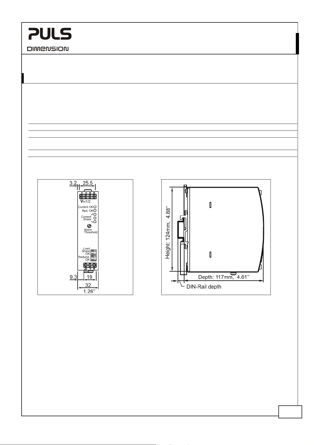
19. PHYSICAL DIMENSIONS AND WEIGHT
Width 32mm 1.26’’
Height 124mm 4.88’’
Depth 117mm 4.61’’
The DIN-rail height must be added to the unit depth to calculate the total required
installation depth.
Weight 310g / 0.69lb
DIN-Rail Use 35mm DIN-rails according to EN 60715 or EN 50022 with a height of 7.5 or 15mm.
Housing material Body: Aluminium alloy
Cover: zinc-plated steel
Installation clearances See chapter 2
Fig. 19-1 Front view Fig. 19-2 Side view
Jul. 2017 / Rev. 1.4 DS-YR20.246-EN All parameters are typical values specified at 24V, 20A output current, 25°C ambient and
after a 5 minutes run-in time unless otherwise noted.
14/19
Page 15

YR20.246
Y-Series
24-28V, 20A, DUAL REDUNDANCY MODULE
20. ACCESSORIES
20.1. ZM11.SIDE - SIDE MOUNTING BRACKET
This bracket is used to mount the YR20.246 redundancy module sideways with or without utilizing a DIN-Rail.
The two aluminum brackets and the black plastic slider of the unit have to be detached, so that the steel brackets can
be mounted.
For sideway DIN-rail mounting, the removed aluminum brackets and the black plastic slider need to be mounted on
the steel bracket.
Side mounting without DIN-
Fig. 20-1
rail brackets
Side mounting with DIN-rail
Fig. 20-2
brackets
Fig. 20-3
Mounting Dimensions
Side mounting bracket
Jul. 2017 / Rev. 1.4 DS-YR20.246-EN All parameters are typical values specified at 24V, 20A output current, 25°C ambient and
after a 5 minutes run-in time unless otherwise noted.
15/19
Page 16

YR20.246
Y-Series
24-28V, 20A, DUAL REDUNDANCY MODULE
21. APPLICATION NOTES
21.1. USING ONLY ONE INPUT INSTEAD OF BOTH CHANNELS
Using only one input instead of both is allowed up to a nominal input current of 12A (at max. +45°C ambient
temperature) or 10A (at max. +70°C ambient temperature).
The load share feature is disabled in cases one input voltage is not present or the level of the input voltage is below a
certain value. The MOSFET will be on in such cases.
However, it is always recommended to connect both input path in parallel for reduced power losses and voltage drop.
When this is not possible, the following values can be expected:
Voltage drop, input to output typ. 0.15V
Power losses typ.
2.6W
Standby power losses typ. 1.1W
Fig. 21-1 Input to output voltage drop when only one
Voltage Drop, typ.
200mV
input is used
60°C
25°C
150mV
at 1x10A, 25°C, see Fig. 21-1
at 1x10A, 25°C, see Fig. 21-3
Fig. 21-2 Test setup for voltage drop measurements
Power
Supply
24V, 12A
+
-
YR20.246
1
I
A
Input 1
V
U
1
Output
Variable
Load,
I
OUT
0-12A
Output
A
V
U
OUT
100mV
50mV
0mV
2.5A 7.5A
Input/ Output Current
10A5A0
12.5A
Input 2
Voltage Drop
Fig. 21-3 Power losses when only one input is used Fig. 21-4 Test setup for power loss measurements
Power Losses, typ
4W
3W
2W
1W
60°C
25°C
Power
Supply
24V, 12A
+
-
YR20.246
I
1
A
Input 1
V
U
1
0
2.5A 7.5A
Output Current
10A5A0
12.5A
Input 2
Losses
U1=
U
OUT
-*I
1
I
OUT
*
Output
Output
I
OUT
A
U
OUT
V
U1=
Variable
Load,
0-12A
U
OUT
-
Jul. 2017 / Rev. 1.4 DS-YR20.246-EN All parameters are typical values specified at 24V, 20A output current, 25°C ambient and
after a 5 minutes run-in time unless otherwise noted.
16/19
Page 17

YR20.246
Y-Series
24-28V, 20A, DUAL REDUNDANCY MODULE
21.2. RECOMMENDATIONS FOR REDUNDANCY
Recommendations for the configuration of redundant power systems:
- Use separate input fuses for each power supply.
- Use three-phase power supplies to gain functional safety if one phase fails.
- When single-phase power supplies are utilized connect them to different phases or mains circuits if possible.
- Set the power supply in “Parallel-Use” mode if this feature is available
- It is desirable to set the output voltages of all power supplies to the same value.
21.3. INDUCTIVE AND CAPACITIVE LOADS
The unit is designed to supply any kind of loads, including unlimited capacitive and inductive loads.
21.4. SIDEWARDS INSTALLATION CLEARANCES
The minimum clearance recommendations are defined in chapter 2.
Normally, the following installation clearance are recommended: 40mm on top, 20mm on the bottom, 5mm on the
left and right sides when the device is loaded permanently with more than 50% of the rated power. Increase this
clearance to 15mm in case the adjacent device is a heat source (e.g. another
power supply).
The clearance between the power supplies and the redundancy module can be
reduced to zero under the following conditions:
- 1+1 redundancy application with maximum 12A output current.
- The power supplies are from the PULS DIMENSION series.
- The redundancy module is placed between the two power supplies.
- The output voltage is set to the same level on both power supplies.
+
-
Output
Power
Supply
Input
-
+
+
IN 2
IN 1
YR20.246
Redundancy
Module
Output
+
-
Load
-
+
Output
Power
Supply
Input
0mm0mm
-
Jul. 2017 / Rev. 1.4 DS-YR20.246-EN All parameters are typical values specified at 24V, 20A output current, 25°C ambient and
after a 5 minutes run-in time unless otherwise noted.
17/19
Page 18

YR20.246
Y-Series
24-28V, 20A, DUAL REDUNDANCY MODULE
21.5. 1+1 REDUNDANCY UP TO 10A
1+1 Redundancy up to 10A requires two 10A power supplies and one YR20.246 redundancy module.
Note: Use separate mains systems for each power supply whenever it is possible
Fig. 21-5 Wiring diagram, 1+1 Redundancy, 10A output current
++
--
Output
24V,10A
Power
Supply
Input
LNPE
I
L
N
PE
++
Output
24V,10A
Power
Supply
Input
LNPE
I
--
--
1
Input
Load Share
OK
Redudnadcy
OK
YR20.246
Redundancy
Module
Output
optional
Input
-
++
2
o
o
o
o
+
Load
Share
Warning
Failure
Monitor
10A
Load
Jul. 2017 / Rev. 1.4 DS-YR20.246-EN All parameters are typical values specified at 24V, 20A output current, 25°C ambient and
after a 5 minutes run-in time unless otherwise noted.
18/19
Page 19
YR20.246
Y-Series
24-28V, 20A, DUAL REDUNDANCY MODULE
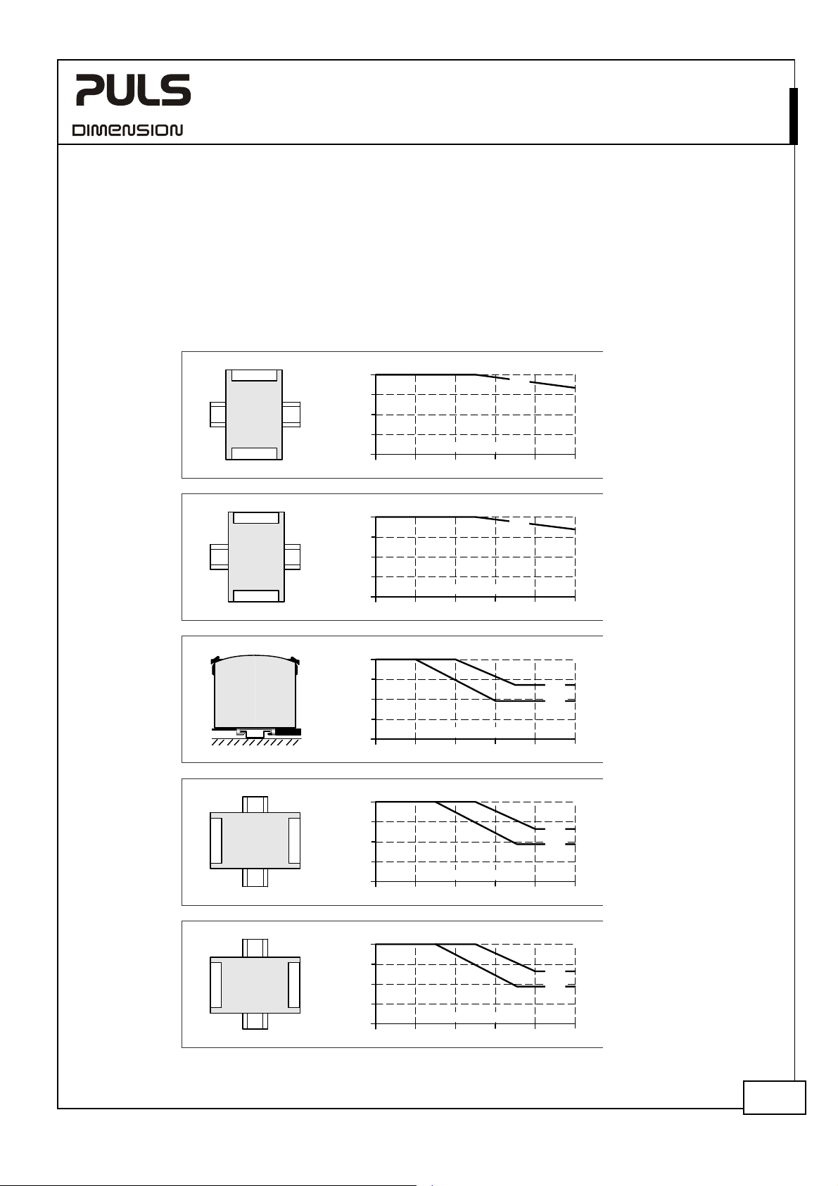
21.6. MOUNTING ORIENTATIONS
Mounting orientations other than input terminals on the bottom and output on the top require a reduction in
continuous output power or a limitation in the maximum allowed ambient temperature. The amount of reduction
influences the lifetime expectancy of the power supply. Therefore, two different derating curves for continuous
operation can be found below:
Curve A1 Recommended output current.
Curve A2 Max allowed output current (results in approximately half the lifetime expectancy of A1).
Fig. 21-6
Mounting
Orientation A
(Standard
orientation)
Fig. 21-7
Mounting
Orientation B
(Upside down)
INPUT
Redundancy
Module
OUTPUT
INPUT
OUTPUT
Module
Redundancy
Fig. 21-8
Mounting
Orientation C
(Table-top
mounting)
Fig. 21-9
Mounting
Orientation D
(Horizontal cw)
OUTPUT
Redundancy
Module
INPUT
Fig. 21-10
Mounting
Orientation E
(Horizontal ccw)
INPUT
Module
Redundancy
OUTPUT
Output Current
24A
18
12
6
0
Ambient Temperature
20 30 40 50
Output Current
24A
18
12
6
0
Ambient Temperature
20 30 40 50
Output Current
24A
18
12
6
0
Ambient Temperature
20 30 40 50
Output Current
24A
18
12
6
0
Ambient Temperature
20 30 40 50
Output Current
24A
18
12
6
0
Ambient Temperature
20 30 40 50
A
1
70°C
60
A
1
60
60
60
60
70°C
A
2
A
1
70°C
A
2
A
1
70°C
A
2
A
1
70°C
Jul. 2017 / Rev. 1.4 DS-YR20.246-EN All parameters are typical values specified at 24V, 20A output current, 25°C ambient and
after a 5 minutes run-in time unless otherwise noted.
19/19
 Loading...