

Page 1
1 EN UF Instruction Manual Buffer Unit
2 DE UF Bedienungsanleitung Puffermodul
3 FR UF Manual d'instructions Module tampon
4 ES UF Manual de instrucciones Módulo búfer
5 IT UF Manuale di Istruzione Modulo tampone
6 PT UF Manual de Instruções Módulo tampão
UF Series
Read this first! English 1
Before operating this unit please read this manual thoroughly and retain this manual for future reference! This device may only be installed and put into operation by qualified personnel. If damage or
malfunction should occur during operation, immediately turn power off and send unit to the factory for inspection. The unit does not contain serviceable parts.
The information presented in this document is believed to be accurate and reliable and may change without notice. For any clarifications the English translation will be used.
Intended Use: This device is designed for installation in an enclosure and is intended for general use such as in industrial control, office, communication, and instrumentation equipment. Do not use
this device in equipment, where malfunction may cause severe personal injury or threaten human life.
WARNING
1) Turn power off before working on the device. Protect against inadvertent re-powering.
2) Make sure that the wiring is correct by following all local and national codes.
3) Do not modify or repair the unit.
4) Do not open the unit as high voltages are present inside.
5) Use caution to prevent any foreign objects from entering the housing.
6) Do not use in wet locations or in areas where moisture or condensation can be expected.
Risk of electrical shock, fire, personal injury or death.
Vor Inbetriebnahme lesen! Deutsch 2
Bitte lesen Sie diese Warnungen und Hinweise sorgfältig durch, bevor Sie das Gerät in Betrieb nehmen. Bewahren Sie die Anleitung zum Nachlesen auf. Das Gerät darf nur durch fachkundiges und
qualifiziertes Personal installiert werden. Bei Funktionsstörungen oder Beschädigungen schalten Sie sofort die Versorgungsspannung ab und senden das Gerät zur Überprüfung ins Werk. Das Gerät
beinhaltet keine Servicebauteile. Die angegebenen Daten dienen allein der Produktbeschreibung und sind nicht als zugesicherte Eigenschaften im Rechtssinne aufzufassen. Im Zweifelsfall gilt der
englische Text.
Bestimmungsgemäßer Gebrauch: Dieses Gerät ist für den Einbau in ein Gehäuse konzipiert und zur Verwendung für allgemeine elektronische Geräte, wie z.B. Industriesteuerungen, Bürogeräte,
Kommunikationsgeräte oder Messgeräte geeignet. Benutzen Sie dieses Gerät nicht in Steuerungsanlagen, in denen eine Funktionsstörung zu schweren Verletzungen führen oder Lebensgefahr
bedeuten kann.
WARNUNG
1) Schalten Sie die Eingangsspannung vor Installations-, Wartungs- oder Änderungsarbeiten ab und sichern Sie diese gegen unbeabsichtigtes Wiedereinschalten.
2) Sorgen Sie für eine ordnungsgemäße und fachgerechte Verdrahtung.
3) Führen Sie keine Änderungen oder Reparaturversuche am Gerät durch.
4) Gerät niemals öffnen. Im Inneren befinden sich gefährliche Spannungen.
5) Verhindern Sie das Eindringen von Fremdkörpern, wie z.B. Büroklammern und Metallteilen.
6) Betreiben Sie das Gerät nicht in feuchter Umgebung oder in einer Umgebung, bei der mit Betauung oder Kondensation zu rechnen ist.
Missachtung nachfolgender Punkte kann einen elektrischen Schlag, Brände, schwere Unfälle oder Tod zur Folge haben.
A lire avant mise sous tension! Français 3
Merci de lire ces instructions de montage et d'entretien avant de mettre l'alimentation sous tension. Conservez ce manuel qui vous sera toujours utile. Cette alimentation doit être installée par du
personnel qualifié et compétent. Le déclenchement du fusible interne traduit très probablement un défaut au niveau de l'appareil. Si un défaut quelconque apparaît en cours de fonctionnement,
débrancher au plus vite l'alimentation. Dans ce deux cas de figure, il convient de faire contrôler l'alimentation en usine! Les données indiquées dans ce document servent uniquement à donner une
description du produit et n'ont aucune valeur juridique. En cas de divergences, le texte anglais fait foi.
Utilisation: Cet appareil est conçu pour être installé dans une armoire et pour tous les équipements électroniques, tel que l'équipement industriel de commande, l'équipement de bureau, le matériel de
communication et les instruments de mesures. N'utilisez pas cet appareil sur des installations dans lesquels un problème de fonctionnement de l'alimentation pourrait causer des blessures graves ou
menacer la vie humaine.
AVERTISSEMENT
1) débrancher l'installation avant toute intervention sur l'alimentation (ou démontage) et s'assurer qu'il n'y a pas risque de redémarrage.
2) s'assurer que le câblage a été fait selon les prescriptions
3) ne pas effectuer de réparations ou modifications sur l'alimentation
4) ne pas ouvrir l'appareil. Des tensions importantes passent à l'intérieur.
5) veiller à ce qu'aucun objet ne rentre en contact avec l'intérieur de l'alimentation (trombones, pièces métalliques)
6) ne pas faire fonctionner l'appareil dans un environnement humide ou à l'extérieur, non protégé. Ne pas utiliser l'appareil dans un environnement où il peut y avoir de la condensation.
Prendre en compte les points suivants, afin d'éviter toute détérioration électrique, incendie, dommage aux personnes ou mort
Lea primero! Español 4
Conserve este manual como referencia para futuras consultas. La fuente de alimentación solo puede ser instalada y puesta en funcionamiento por personal cualificado. Por favor lea detenidamente
este manual antes de conectar la fuente de alimentación. Cuando se funde un fusible interno, existe gran probabilidad de un fallo interno en el equipo.Si se produce un fallo o mal funcionamiento
durante la operación, desconecte inmediatamente la tensión de alimentación. En ambos casos, el equipo debe ser inspeccionado en fábrica. La información presentada en este documento es exacta
y fiable en cuanto a la descripción del producto y puede cambiar sin aviso. En casa de duda, prevalece el texto inglés.
Uso apropiado: Este equipo ha sido diseñado para su instalación en un ambiente cerrado y ha sido concebido para uso general en instalaciones de control industrial, oficinas, comunicaciones y
equipos de instrumentación. No emplee esta unidad en equipos, donde un mal funcionamiento puede ocasionar lesiones graves o riesgo mortal.
ADVERTENCIA
1) No conectar nunca la unidad sin conexión de puesta a tierra.
2) Desconectar la tensión de red antes de trabajar en la fuente de alimentación. Evite una posible reconexión involuntaria.
3) Asegurarse de que el cableado es correcto de acuerdo a los códigos locales y nacionales.
4) No realizar ninguna modificación o reparación de la unidad.
5) No abrir nunca la unidad. En el interior existe riesgo de altas tensiones.
6) Evitar la introducción en la carcasa de objetos extraños.
Germany +49 89 9278 0 www.pulspower.de Austria +43 27 64 32 13 www.pulspower.at
China +86 512 62881820 www.pulspower.cn Singapore +65 6684 2310 www.pulspower.sg
France +33 478 668 941 www.pulspower.fr Switzerland +41 56 450 18 10 www.pulspower.ch
North America +1 630 587 9780 www.pulspower.us United Kingdom +44 1525 84 1001 www.pulspower.co.uk
Riesgo de descarga eléctrica, incendio, accidente grave o muerte.
Headquarters:
PULS GmbH
Elektrastr. 6
81925 Munich, Germany
Page 2
Instruction Manual Bedienungsanleitung
A
A
Leggere prima questa parte! Italiano 5
Prima di collegare il sistema di alimentazione elettrica si prega di leggere attentamente le seguenti avvertenze. Conservare le istruzioni per la consultazione futura. Il sistema di alimentazione elettrica
deve essere installato solo da personale competente e qualificato. In caso di intervento del fusibile interno, molto probabilmente l'apparecchio è guasto. Se durante il funzionamento si verificano anomalie
o guasti, scollegare immediatamente la tensione di alimentazione. In entrambi i casi è necessario far controllare l'apparecchio dal produttore! I dati sono indicati solo a scopo descrittivo del prodotto e non
vanno considerati come caratteristiche garantite dell'apparecchio.In caso di differenze o problemi è valido il testo inglese
Uso previsto: Questo apparecchio è previsto per il montaggio in un rack per moduli elettronici, ad esempio per controllori industriali, apparecchiature per ufficio, unità di comunicazione o apparecchi di
misura. Non utilizzare questo apparecchio in apparati o impianti dove il malfunzionamento può causare danni alla persona o pericolo di vita.
AVVERTENZA
Il mancato rispetto delle seguenti norme può provocare folgorazione elettrica, incendi, gravi incidenti e perfino la morte.
1) Prima di eseguire interventi di installazione, di manutenzione o di modifica scollegare la tensione di rete ed adottare tutti i provvedimenti necessari per impedirne il ricollegamento non intenzionale.
2) Assicurare un cablaggio regolare e corretto.
3) Non tentare di modificare o di riparare da soli l'apparecchio.
4) Non aprire l'apparecchio. Al suo interno sono applicate tensioni elettriche pericolose.
5) Impedire la penetrazione di corpi estranei nell'apparecchio, ad esempio fermagli o altri oggetti metallici.
6) Non far funzionare l'apparecchio in un ambiente umido. Non far funzionare l'apparecchio in un ambiente soggetto alla formazione di condensa o di rugiada.
Leia primeiro! Portuguès 6
Recomendamos a leitura cuidadosa das seguintes advertências e observações, antes de colocar em funcionamento a fonte de alimentação. Guarde as Instruções para futura consulta, em casos de
dúvida. A fonte de alimentação deverá ser instalada apenas por profissionais da área, tecnicamente qualificados. Se o fusível interno se fundir, é grande a possibilidade de existir um defeito no aparelho.
Se por acaso, durante a utilização ocorrer algum defeito de funcionamento ou dano, desligue imediatamente a tensão de alimentação. Em ambos os casos, será necessária uma verificação na Fábrica!
Os dados mencionados têm como finalidade somente a descrição do produto, e não devem ser interpretados como propriedades garantidas no sentido jurídico. Em caso de duvidas aplica-se o texto em
inglês.
Utilize: Apenas para o fim pré-estabelecido. Este aparelho foi concebido para ser montado dentro de invólucros, caixas ou armários para aparelhos eletrônicos em geral, como, por exemplo, comandos
de instalações industriais, aparelhos para escritórios, aparelhos de comunicação ou instrumentos de medida e quadros eléctricos. Não utilize este aparelho em instalações, nos quais um defeito de
funcionamento poderá causar danos graves ou significar risco de morte.
ATENÇÃO
não observância ou o incumprimento dos pontos a seguir mencionados, poderá causar uma descarga elétrica, incêndios, acidentes graves ou morte.
1) Antes de trabalhos de instalação, manutenção ou modificação, desligue a tensão de alimentação, protegendo-a contra uma nova ligação involuntária.
2) As ligações devem ser efectuadas apenas por profissionais competentes.
3) Não efectue nenhuma modificação ou tentativa de reparação no aparelho. Quando necessário contacte o seu distribuidor.
4) Não abra o aparelho mesmo quando desligado. No seu interior existem condensadores que podem estar carregados electricamente.
5) Proteger a fonte de alimentação contra a introdução inadvertida de corpos metálicos, como por ex., clipes ou outras peças de metal.
6) Não usar o aparelho em ambientes húmidos. Não usar o aparelho em ambientes propensos a condensações.
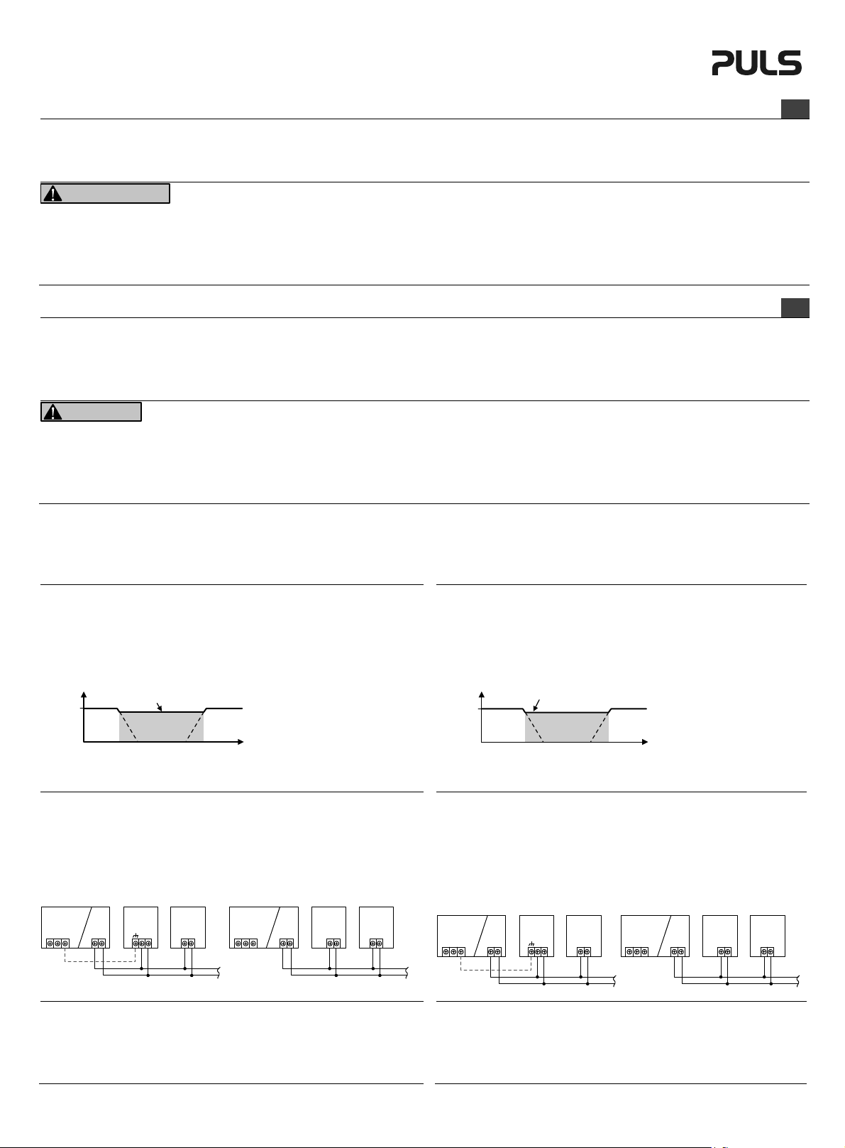
Product Description:
Buffer modules are supplementary devices for regulated DC 24V or DC 48V power supplies, which
can be used for various purposes:
- To deliver power to bridge failures of the DC voltage supply system
- To extend the hold-up time after loss of the AC power
- To deliver extra short-term peak current above the current rating of the power supply
In times when the power supply provides sufficient voltage (power supply mode), the buffer unit
stores energy in the integrated electrolytic capacitors. In case of a voltage dip or loss, this energy is
released to the DC bus in a regulated process (buffer mode).
DC-Bus
Voltage
Power
Supply
Mode
Service-free electrolytic capacitors are used for storing the energy. This allows useage even at
ambient temperatures up to +70°C.
For higher current demands or longer buffer times, multiple buffer modules can be connected in
parallel.
Installation
Use DIN-rails according to EN 60715 or EN 50022 with a height of 7.5 or 15mm.
Do not obstruct air flow as the unit is convection cooled. Ventilation grid must be kept free of any
obstructions.
Keep minimum 40mm on the top and 20mm on the bottom installation clearances. No sideways
installation clearances are required.
The unit must be powered from a SELV source (according to IEC 60950-1), PELV source (according
to IEC 62477-1) or an Isolated Secondary Circuit (according to UL 508) power source.
Wiring diagram:
Power
Supply
PE
+
L
N
UF20.xxx UF40.xxx
CE Marking
The buffer module is suitable for applications in industrial environment as well as in residential,
commercial and light industry environment without any restrictions. The device complies with FCC
Part 15 rules.
CE mark is in conformance with EMC guideline.
EMC Immunity: EN 61000-6-1, EN 61000-6-2
EMC Emission EN 61000-6-3, EN 61000-6-4, FCC Part 15 Class B
-
Threshold Voltage
Buffer
Mode
Buffer
Module
+
-
optional
Load
Gerätebeschreibung
Puffermodule sind Ergänzungsgeräte für geregelte DC 24V oder DC 48V Netzgeräte und können
für folgende Anforderungen genutzt werden:
- Strom zu liefern um kurzer Unterbrechungen im DC-Netz zu überbrücken.
- Haltezeit der Ausgangsspannung nach einem Verlust der AC-Spannung zu verlängern.
- Zusätzlichen Strom zur Abdeckung kurzer Laststromspitzen zu liefern
Im Normalbetrieb (Netzgerätmodus) werden interne Elektrolytkondensatoren geladen. Bei
Spannungseinbruch wird die gespeicherte Energie wieder kontrolliert und geregelt an den DCBus abgegeben (Puffermodus).
optional
Puffer-
modul
Schwellspannung
für Pufferbetrieb
Puffermodus
Ver-
braucher
+
+
-
-
Netzgerät-
modus
Stromversorgung
L
N
t
Puffer-
PE
modul
+
-
Ver-
braucher
+
+
-
DC-Bus
Power
Supply
Mode
t
Power
Supply
PE
L
+
-
N
Buffer
Module
+
-
Load
+
+
-
-
Spannung
Netzgerät-
modus
Hochwertige, wartungsfreie Elektrolytkondensatoren dienen dabei als Energiespeicher und
erlauben einen Einsatz bei Umgebungstemperaturen bis +70°C.
Bei höherem Strombedarf oder zur Überbrückung längerer Ausfallzeiten können mehrere
Puffermodule parallel geschaltet werden.
Installation
Geeignet für DIN-Schienen entsprechend EN 60715 oder EN 50022 mit einer Höhe von 7,5 oder
15mm.
Luftzirkulation nicht behindern! Das Gerät ist für Konvektionskühlung ausgelegt. Es ist für
ungehinderte Luftzirkulation zu sorgen.
Über dem Gerät sind minimal 40mm und unterhab des Geräts 20mm Abstand zu den nächsten
Geräten einzuhalten. Seitlich sind keine Abstände erforderlich.
Das Gerät muss von einer Spannungsquelle versorgt werden, welche entweder den SELV (IEC
60950-1), PELV (IEC 62477-1) oder den „Isolated Secondary Circuit“ (gemäß UL 508)
nforderungen genügen.
Anschlussschema:
Stromversorgung
PE
L
+
N
-
UF20.xxx UF40.xxx
CE Kennzeichnung
Dieses Puffermodul erfüllt die Anforderungen für Anwendungen in industrieller Umgebung und
für den Wohn-, Geschäfts- und Gewerbebereich ohne Einschränkungen. Das Gerät erfüllt auch
die Anforderungen der FCC Teil 15. Das CE Zeichen ist angebracht und erklärt die Erfüllung der
EMV Richtlinie.
Störfestigkeit: EN 61000-6-1, EN 61000-6-2
Störaussendung: EN 61000-6-3, EN 61000-6-4, FCC Part 15 Klasse B
-
Page 3

Instruction Manual Bedienungsanleitung
Technical Data 1) Technische Daten
Suitable Power Supplies Geeignete Stromversorgungen check accessory list of the
Supply Voltage 9) Versorgungsspannung
Required Voltage to Charge the Capacitor Erforderliche Spannung zum Laden des
Kondensators
Threshold Voltage for Buffer Mode Schwellspannung für Puffermodus typ. 22.5V 2) / VIN –1V
Current Consumption stand-by mode Stromaufnahme im Bereitschaftsbetrieb typ. 80mA 40mA 80mA
during charging während des Ladevorgang max. 600mA 500mA 600mA
Buffer Voltage Pufferspannung typ. 22.5V 2) / VIN –1V
Buffer Current 4) Pufferstrom
Buffer Time Pufferzeit min. 200ms at 22.5V, 20A
typ. 310ms at 22.5V, 20A
typ. 43s at 22.5V, 0.1A 21s at 45V, 0.1A 62s at 22.5V, 0.1A
Charging Time 8) Ladezeit
8)
typ. 25s / 18s 29s / 21s 45s / 34s
Power Losses in Stand-by Mode Verluste im Bereitschaftsbetrieb typ. 1.9W 1.9W 1.9W
Operational Temperature Range Betriebstemperaturbereich nom. -25°C - +70°C -25°C - +70°C -25°C - +70°C
Storage Temperature Range Lagertemperaturbereich nom. -40°C - +85°C -40°C - +85°C -40°C - +85°C
Humidity 5) Feuchte
5)
IEC 60068-2-30 5 - 95% r.H. 5 - 95% r.H. 5 - 95% r.H.
Vibration Sc hwingen IEC 60068-2-6 2g 2g 1g
Shock Schocken IEC 60068-2-27 30g 6ms, 20g 11ms 30g 6ms, 20g 11ms 15g 6ms, 10g 11ms
Degree of Pollution (non-conductive) Verschmutzungsgrad (nicht leitend) IEC 62477-1 2 2 2
Degree of Protection Schutzart EN 60529 IP20 IP20 IP20
Class of Protection Schutzklasse IEC 61140 II II II
Isolation Voltage against Housing Isolation gegen Gehäuse 500Vac 500Vac 500Vac
Isolation Power vs. Signal Terminals Isolation Leistungs- gegen Signalklemmen 500Vac 500Vac 500Vac
Parallel Use 6) Parallelschaltbar
Dimensions 7) (WxHxD) Abmessungen
Weight Gewicht 740g / 1.63lb 740g / 1.63lb 1040g / 2.3lb
1) All parameters are specified at 24Vdc or 48Vdc supply voltage, 25°C ambient temperature and
after a 5 minutes run-in time unless otherwise noted.
2) Fixed mode: If terminal voltage falls below this level, buffering starts and the supply voltage will
be kept at this level.
3) Variable mode: If the supply voltage drops by 1V (24V versions) or 2V (48V version) buffering
starts and the supply voltage will be kept at this level.
4) Buffer current is electronically limited to this value.
5) Do not energize while condensation is present.
6) To increase the power in buffer mode or the buffer time.
7) Depth without DIN-rail and signal connector.
8) Initial charging / recharging shortly after a buffer event.
9) At voltages within the supply voltage range, control functions such as LEDs, monitoring features,
signals, etc. are functioning normally.
Terminals and Wiring
Use appropriate copper cables that are designed for a minimum operating temperatures of 60°C (for
ambient up to 45°C) and 75°C (for ambient up to 60°C). Follow national installation codes and
regulations! Ensure that all strands of a stranded wire enter the terminal connection! Ferrules are
allowed.
Power terminals Signals terminals
UF20 UF40 UF20, UF40
Spring-clamp Screw terminal Plug connector (screw type)
Solid wire max. 6mm
Stranded wire max. 4mm
American wire gauge 20-10 AWG 22-8 AWG 22-14 AWG
Wire diameter*) max. 2.8mm max. 5.2mm max. 2.25mm
Wire stripping length 10mm / 0.4inch 12mm / 0.5inch 6mm / 0.24inch
Tightening torque not applicable 2.3Nm / 20.5lb.in 0.4Nm / 3.5lbs.in
*) including ferrules
2
max. 16mm
2
max. 10mm
Selection of the Back-up Threshold Voltage
The buffer behavior can be selected with the back-up jumper selector.
Position „2-3“: Fixed Mode:
Position „1-2“: Variable Mode:
Factory setting is position „2-3“, a missing jumper equals position „2-3“.
If the supply voltage falls below 22.5V (24V versions) resp. 45V (48V version),
buffering starts and the supply voltage will be kept at this level.
This adjustment is recommended for back-feeding loads, if the buffer module is
placed close to the load or whenever in doubt.
If the supply voltage drops by 1V (24V versions) or 2V (48V version) buffering starts
and the supply voltage will be kept at this level.
If the supply voltage drops slower than 0.54V/s (24V versions) resp. 1.1V/s (48V
version) buffering does not start before 22.5V resp. 45V.
This adjustment is recommended for any application where 22.5V or 45V are too
low for the application or when the buffer unit is placed close to the power supply.
1)
UF20.241 UF20.481 UF40.241
9)
nom. DC 24V (-20%/+25%) DC 48V (-20%/+25%) DC 24V (-20%/+25%)
power supply datasheet
check accessory list of the
power supply datasheet
check accessory list of the
power supply datasheet
typ. 23V 46V 23V
3)
45.0V 2) / VIN –2V 3) 22.5V 2) / VIN –1V
3)
4)
nom. 20A 20A 40A
430ms at 22.5V, 10A
670ms at 22.5V, 10A
6)
Yes / Ja Yes / Ja Yes / Ja
7)
(BxHxT) nom. 64x124x102mm 64x124x102mm 64x124x142mm
1) Alle Werte gelten bei 24Vdc bzw. 48Vdc Versorgungsspannung, 25°C Umgebungstemperatur und nach einer Aufwärmzeit von 5 Minuten, wenn nichts anderes angegeben ist.
2) Feste Schwelle: Fällt die Klemmenspannung unterhalb diesen Wert, schaltet das Gerät in
den Puffermodus und hält die Versorgungsspannung auf diesen Wert.
3) Variable Schwelle: Sinkt die Versorgungsspannung um 1V (24V Modelle) oder 2V (48V
Modell) ab, schaltet das Gerät in den Puffermodus und hält die Versorgungsspannung auf
diesen Wert.
4) Pufferstrom wird auf diesen Wert elektronisch begrenzt.
5) Nicht betreiben, solange das Gerät Kondensation aufweist.
6) Zur Leistungserhöhung im Pufferbetrieb oder zur Pufferzeitverlängerung.
7) Tiefe ohne DIN-Schiene und Signalstecker.
8) Erstaufladung / Aufladung anschließend eines Pufferfalls
9) Die Versorgungsspannung gibt den Spannungsbereich an, in dem alle Kontrollfunktionen wie
LEDs, Überwachungsfunktionen, Signale, usw. ordnungsgemäß funktionieren.
Anschlussklemmen und Verdrahtung
Verwenden Sie geeignete Kupferkabel, die mindestens für 60°C bei Umgebungstemperaturen
bis zu 45°C und 75°C bei einer Umgebungstemperaturen bis zu 60°C zugelassen sind.
Beachten Sie nationale Bestimmungen und Installationsvorschriften! Stellen Sie sicher, dass
keine einzelnen Drähte von Litzen abstehen. Aderendhülsen sind erlaubt.
Leistungsanschlüsse Signalanschlüsse
UF20 UF40 UF20, UF40
2
2
max. 2.5mm2
max. 2.5mm2
Federkraftklemmen Schraubanschluss Steckverbinder
Starrdraht max. 6mm
Litze max. 4mm
AW G 20-10 AW G 22-8 AWG 22-14 AWG
Drahtdurchmesser
Abisolierlänge 10mm / 0,4inch 12mm / 0,5inch 6mm / 0,24inch
Anzugsdrehmoment nicht zutreffend 2,3Nm / 20,5lb.in 0,4Nm / 3,5lbs.in
*) inklusive Aderendhülsen
Einstellung der Triggerschwelle für den Pufferbetrieb
Mittels der „Back-up Jumper“ Steckbrücke lässt sich das Verhalten des Pufferbetriebs einstellen.
Stellung „2-3“: Feste Schwelle:
Stellung „1-2“: Variable Schwelle:
Werkseinstellung ist Stellung „2-3“, eine fehlende Steckbrücke entspricht Stellung „2-3“.
*)
Fällt die Versorgungsspannung unterhalb von 22,5V (24V Modelle) bzw. 45V
(48V Modell), schaltet das Gerät in den Puffermodus und hält die
Versorgungsspannung auf diesen Wert. Diese Einstellung wird bei
rückspeisenden Lasten empfohlen, wenn das Puffermodul nahe der Last
platziert ist oder in allen Fällen, bei denen Zweifel besteht.
Sinkt die Versorgungsspannung um 1V (24V Modelle) oder 2V (48V Modell),
schaltet das Gerät in den Puffermodus und hält die Versorgungsspannung auf
diesen Wert.
Sinkt die Versorgungsspannung langsamer als mit 0,54V/s (24V Modelle) bzw.
mit 1,1V/s (48V Modell) startet die Pufferung aber erst bei 22,5V bzw. 45V.
Diese Einstellung wird empfohlen, wenn die Spannung von 22,5V oder 45V nicht
ausreichend ist oder wenn das Puffermodul nahe am Netzgerät platziert ist.
2
2
max. 2,8mm max. 5,2mm max. 2,25mm
45.0V 2) / VIN –2V 3) 22.5V 2) / VIN –1V
100ms at 45V, 20A
200ms at 45V, 10A
150ms at 45V, 20A
300ms at 45V, 10A
max. 16mm
max. 10mm
2
2
160ms at 22.5V, 40A
320ms at 22.5V, 20A
250ms at 22.5V, 40A
500ms at 22.5V, 20A
max. 2,5mm2
max. 2,5mm2
3)
3)
Page 4

Instruction Manual Bedienungsanleitung
A
A
Status LED and Signal Outputs
Status LED “Active” signal “Ready” signal
Stand-by mode ON Low High
Charging mode Slow flashing Low Low
Buffer mode Fast flashing High Low
ctivated Inhibit OFF Low Low
No input power OFF Low Low
The Active and Ready signal outputs are galvanically isolated from the power port and may also
operate with an external PELV control voltage. The positive pole of the voltage must always be
connected with pin 6.
The signal outputs can be loaded with maximum 35Vdc, 10mA (24V versions) or 60Vdc, 6mA (48V
version). The signal leakage current is smaller than 50µA.
Inhibit Input
Buffering can be disabled or interrupted with the Inhibit input. Therefore, pin 6 should be connected
to the positive pole of the terminal voltage or to the external PELV control voltage and pin 9 must be
connected to the corresponding negative pole.
The unit does not buffer (or stops buffering) if the voltage between pin 6 and pin 9 is higher than
10V. Below 6V buffering will function again.
The current of the inhibit input is limited to 4mA. The voltage between pin 6 and pin 9 must not
exceed 35Vdc (24V versions) or 60V (48V version).
Functional diagram / Funktionsschaltbild
+
*)
+
-
-
Chassis
Ground
Back-up
Level
Jumper
*)
*) UF20 only
Reverse-
Polarity
Protection
Safety and
Over-
Voltage
Protection
Input / Output
Voltage Monitor
Fig. 3 / Bild 3
UF20 Buffer time / Pufferzeit
Buffer Current, typ.
20A
15
10
5
a
b
0
0.6 0.9 1.2 1.5 1.8 2.1 2.4 2.4
00.3 3s
Fig. 6 / Bild 6
Signal wiring / Signalverdrahtung
Fig. 1 / Bild 1
Buffer Capacitor
Charger &
Inrush Limiter
Buffer Capacitor
Discharger
a: UF20.241
b: UF20.481
Buffer Time
Buffer
Capacitor
Shut-Down
Buffer
Capacitor
Optokoppler
+
-
Ready Monitor
Active Monitor
Optokoppler
+
-
Optokoppler
UF40 Buffer time / Pufferzeit
Buffer Current, typ.
40A
30
20
10
0
0.6 0.9 1.2 1.5 1.8 2.1 2.4 2.4
UF20 Dimensions / Abmessungen
00.3 3s
Fig. 7 / Bild 7
Status LED und Signalausgänge
Status LED “Active” Signal “Ready” Signal
Stand-by Betrieb ON Low High
Ladebetrieb langsam blinkend Low Low
Pufferbetrieb schnell blinkend High Low
ktiver Inhibit OFF Low Low
Keine Spannung OFF Low Low
Die „Active“ und „Ready“ Signalausgänge sind galvanisch vom Laststromkreis getrennt und
dürfen auch an fremden PELV Steuerspannungen betrieben werden. Pin 6 muss dabei immer
mit dem positiven Pol der Spannung verbunden sein.
Signalbelastung maximal 35Vdc, 10mA (24V Modelle) oder 60Vdc, 6mA (48V Modell),
Signalleckstrom < 50µA.
„Inhibit” Eingang
Mit dem „Inhibit“ Eingang kann eine Pufferung verhindert oder vorzeitig abgebrochen werden.
Pin 6 muss hierzu mit dem positiven Pol der Klemmenspannung oder einer fremden PELV
Steuerspannung verbunden sein. Der „Inhibit“ Pin 9 muss mit dem entsprechenden negativen
Pol dieser Spannung verbunden werden.
Bei Spannungen zwischen Pin 6 und 9 größer 10V erfolgt keine Pufferung oder wird die
Pufferung sofort unterbrochen. Bei Spannungen kleiner 6V ist eine Pufferung möglich.
Der Signalstrom ist auf 4mA begrenzt. Die maximale Spannung zwischen Pin 6 und Pin 9 darf
35Vdc (24V Modelle) oder 60V (48V Modell) nicht überschreiten.
Status
LED
6 (+)
9 Inhibit
8 Ready
7 Active
Line
Voltage
Output
Voltage
Ready
Signal
Active
Signal
Status
LED
Pin 8
Pin 7
Fig. 4 / Bild 4
Buffer Time
Timing diagram / Zeitliches Ablaufdiagramm
Slow Flashing (1.25Hz)
Charging Mode
Fig. 2 / Bild 2
Hold-up Time of Power Supply
Fast Flashing (10Hz)
Standby
Mode
Buffer time for currents up to 2A / Pufferzeit bei Strömen bis 2A
Fig. 5 / Bild 5
Buffer Mode
Buffer Current, typ.
2.0A
1.5
1.0
0.5
c
a
b
a: UF20.241
b: UF20.481
c: UF40.241
0
6912 15
3 18s
Fig. 8 / Bild 8
UF40 Dimensions / Abmessungen
Buffer Time
t
t
t
t
t
+ Vcc
6 (+)
Active
Ready
Inhibit
UF20, UF40
Vcc: 10-35Vdc (24V Version)
10-60Vdc (48V Version)
PU-366.011.00-10A (2016-03)
7
8
5,1V
3mA
9
The information in this document is believed to be accurate and reliable and may change without notice.
 Loading...