

Page 1
U–Series
UBC10.241, UBC10.241-N1
24V, 10A, DC-UPS
5. INPUT
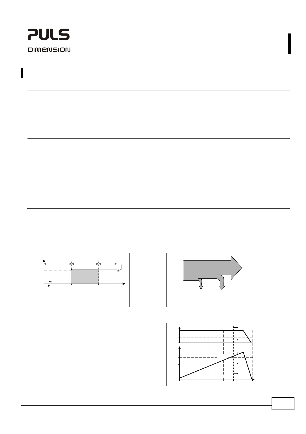
Input voltage nom. DC 24V
Input voltage ranges nom. 22.5 to 30Vdc Continuous operation, see Fig. 5-1
30 to 35Vdc Temporarily allowed, no damage to the DC-UPS *)
Allowed input voltage ripple
1Vpp Bandwidth 400Hz to 1kHz
Allowed voltage between input
and earth (ground)
Turn-on voltage
max. 23Vdc
Input current **) typ. 120mA Internal current consumption
typ. 1.1A Current consumption for battery charging in constant
External capacitors on the input
*) The DC-UPS shows “Check Wiring” with the red LED and buffering is not possible
**) The total input current is the sum of the output current, the current which is required to charge the battery during the
charging process and the current which is needed to supply the DC-UPS itself. See also Fig. 5-2. This calculation does not apply
in overload situations where the DC-UPS limits the output current, therefore see Fig. 5-3.
***) Please note: This is the input current and not the current which flows into the battery during charging. The battery current can
be found in chapter 8.
Fig. 5-1 Input voltage range Fig. 5-2 Input current, definitions
V
OUT
D
AB
35Vdc Absolute maximum input voltage with no damage to the
DC-UPS
0 to 22.5Vdc The DC-UPS switches into buffer mode and delivers
output voltage from the battery if the input was above
the turn-on level before and all other buffer conditions
are fulfilled.
max. 1.5Vpp Bandwidth <400Hz
max. 60Vdc or
42.4Vac
typ. 22.8Vdc The output does not switch on if the input voltage does
not exceed this level.
current mode at 24V input See Fig. 8-2 ***)
No limitation
C
Input
Current
Output
Current
18 30 35V22.50
A: Rated input voltage range
B: Temp. allowed, no harm to the unit
C: Absolute max. input voltage
D: Buffer mode
V
IN
Internal
current
consumption
Current
consumption
for battery
charging
Electronic output current limitation
The DC-UPS is equipped with an electronic output
current limitation. This current limitation works
in a switching mode which reduces the power
losses and heat generation to a minimum. As a
result, the output voltage drops since there is not
enough current to support the load. A positive
effect of the current limitation in switching mode
is that the input current goes down despite an
increase in the output current resulting in less
stress for the supplying source.
May. 2008 / Rev. 1.1 DS-UBC10.241-EN
All parameters are specified at an input voltage of 24V, 10A output load, 25°C ambient and after a 5 minutes run-in time
unless otherwise noted. It is assumed that the input power source can deliver a sufficient output current.
www.pulspower.com Phone +49 89 9278 0 Germany
Fig. 5-3 Input current and output voltage vs.
output current, typ. (battery fully charged)
20V
10
20A
15
10
5
0
Output Voltage
e
r
r
u
C
t
u
p
n
I
O
t
p
u
u
t
C
u
r
r
4812 20A
0
n
e
Overload
t
n
t
15
3/23
Page 2
U–Series
UBC10.241, UBC10.241-N1
24V, 10A, DC-UPS
6. OUTPUT IN NORMAL MODE
Output voltage in normal mode
Voltage drop between input and
output
max. 0.45V At 15A output current, see Fig. 6-1 for typical values
Ripple and noise voltage max. 20mVpp 20Hz to 20MHz, 50Ohm *)
Output current nom. 15A Continuously allowed
Output power nom. 360W Continuously allowed
Short-circuit current min. 17.9A Load impedance 100mOhm, see Fig. 6-2 for typical values
max. 21A Load impedance 100mOhm, see Fig. 6-2 for typical values
Capacitive and inductive loads No limitation
*) This figure shows the ripple and noise voltage which is generated by the DC-UPS. The ripple and noise voltage
might be higher if the supplying source has a higher ripple and noise voltage.
Fig. 6-1 Input to output voltage drop, typ.
Input to Output
Voltage drop
0.4V
0.35
0.3
0.25
0.2
0.15
0.1
0.05
0
468 121416
02 10
u
O
r
u
C
t
p
u
t
nom. DC 24V The output voltage follows the input voltage reduced by
the input to output voltage drop.
max. 0.3V At 10A output current, see Fig. 6-1 for typical values
Fig. 6-2 Output voltage vs. output current in
normal mode at 24V input, typ.
Output Voltage
28V
24
20
t
n
e
r
18A
16
12
8
4
0
0 5 10 15 20
Output Current
25A
May. 2008 / Rev. 1.1 DS-UBC10.241-EN
All parameters are specified at an input voltage of 24V, 10A output load, 25°C ambient and after a 5 minutes run-in time
unless otherwise noted. It is assumed that the input power source can deliver a sufficient output current.
www.pulspower.com Phone +49 89 9278 0 Germany
4/23
Page 3
A
U–Series
UBC10.241, UBC10.241-N1
24V, 10A, DC-UPS
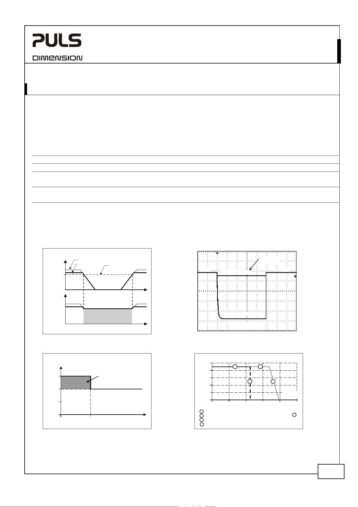
7. OUTPUT IN BUFFER MODE
If the input voltage falls below a certain value (transfer threshold level), the DC-UPS starts buffering without any
interruption or voltage dips. Buffering is possible even if the battery is not fully charged.
Output voltage in buffer mode
Transfer threshold for buffering
Ripple and noise voltage max. 20mVpp 20Hz to 20MHz, 50Ohm
Output current nom. 10A Continuously allowed
15A < 5s with full output voltage *)
Short-circuit current min. 17.9A Load impedance 100mOhm **)
max. 21A Load impedance 100mOhm **)
*) If the output current is in the range between 10A and 15A for longer than 5s, a hardware controlled reduction of the
maximal output current to 10A occurs. If the 10A are not sufficient to maintain the 24V, buffering stops after another 5s. The
buffering is possible again as soon as the input voltage recovers.
**) If the nominal output voltage cannot be maintained in buffer mode, the DC-UPS switches off after 5s to save battery
capacity.
Fig. 7-1 Buffering transition, definitions Fig. 7-2 Transfer behavior, typ.
nom. DC 24V Output voltage is stabilized and independent from
battery voltage
22.45V ±1%, at no load,
22.25V ±1%, at 10A output current
typ. 80mV higher than the output voltage in buffer mode
O
u
t
p
u
Input
voltage
28V
24V
Transfer
threshold
4
2
V
2
2
.
5
2
V
a
t
1
0
A
t
o
V
a
l
t
g
e
4
2
V
t
Output
voltage
t
e
l
a
g
o
t
u
V
n
I
Buffer mode
0
t
V
p
V
I
m
/
s
D
5
0
0
Fig. 7-3 Available output current in buffer
Output
Current
15A
10A
mode
BonusPower
5A
0
05 Sec.
®
Time
Fig. 7-4 Output voltage vs. output current in
Output Voltage
25V
20
15
10
5
0
0
Continuously available
A
Available for 5s then auto switching to curve
B
Buffering will stop after 5s
C
Buffering will stop after 5s
D
buffer mode, typ.
A B
CD
Output
Current
5101520
25
D
May. 2008 / Rev. 1.1 DS-UBC10.241-EN
All parameters are specified at an input voltage of 24V, 10A output load, 25°C ambient and after a 5 minutes run-in time
unless otherwise noted. It is assumed that the input power source can deliver a sufficient output current.
www.pulspower.com Phone +49 89 9278 0 Germany
5/23
Page 4

U–Series
UBC10.241, UBC10.241-N1
24V, 10A, DC-UPS
8. BATTERY
The required 12V VRLA battery is included with this unit. For more details on battery requirements see chapter 26.
Battery voltage
Battery voltage range 9.0 – 15.0V Continuously allowed, except deep discharge
Allowed battery capacity
Battery charging method CC-CV Constant current, constant voltage mode
Battery charging current nom. 1.5A CC-mode, Independent from battery size
End-of-charge-voltage (CV-mode) typ. 13.1 - 14V Automatic setting according to ambient temperature
Battery charging time typ. 3h *)
Battery discharging current **)
typ. 0.3A Buffer mode, 0A output current
Deep discharge protection ***)
typ. 9.0V At 10A output current
*) The charging time depends on the duration and load current of the last buffer event. The numbers in the table represent a
fully discharged battery. A typical figure for a buffer current of 10A is 2h 20Min. for a 5Ah highcurrent battery. Above 40°C
charging time can be longer.
**) The current between the battery and the DC-UPS is more than twice the output current. This is caused by boosting the 12V
battery voltage to a 24V level.
***) To ensure longest battery lifetime, the DC-UPS has a battery deep discharge protection feature included. The DC-UPS stops
buffering when the voltage on the battery terminals of the DC-UPS falls below a certain value.
Fig. 8-1 Battery discharging current
vs. output current, typ.
Battery Current
30A
25
20
15
10
5
0
0
2.5 7.5 10 15A12.55
O
t
p
u
u
t
C
u
nom. DC 12V Maintenance-free 12V VRLA lead acid battery.
protection
max. 35Vdc Absolute maximum voltage with no damage to the
unit.
typ. 7.4V Above this voltage level battery charging is possible
nom. 5Ah High-current version
max. 1.7A Corresponding 24V input current see Fig. 8-2
typ. 21A Buffer mode, 10A output current, 11.5V on the battery
terminal of the DC-UPS, see Fig. 8-1 for other
parameters
max. 50μA At no input, buffering had switched off, all LEDs are
off
typ. 270mA At no input, buffering had switched off, yellow LED
shows “buffer time expired” (max. 15 minutes)
typ. 10.5V At 0A output current
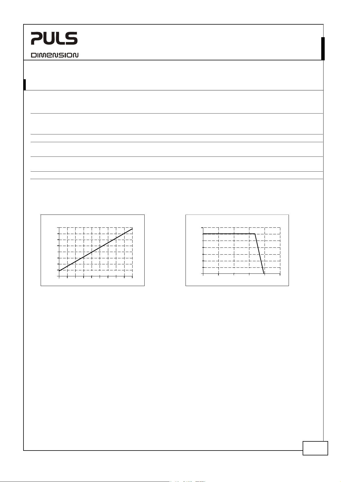
Fig. 8-2 Required input current vs. input
voltage for battery charging
Input Current
1.5A
1.25
1.0
m
a
x
.
(
b
a
t
t
e
r
y
c
ha
r
g
i
n
g
c
u
r
r
e
t
y
p
.
(
ba
t
t
e
r
y
c
h
a
r
g
n
i
n
g
c
ur
r
e
0.75
0.5
0.25
0
23
I
n
p
u
V
o
t
a
t
l
g
e
24 25 26 28V
27
t
1
.
7
A
)
n
t
1
.
5
A
)
Voltage on
battery terminal
of the DC-UPS:
A:
10.5V
B:
11V
C:
12V
r
r
e
n
t
A B C
May. 2008 / Rev. 1.1 DS-UBC10.241-EN
All parameters are specified at an input voltage of 24V, 10A output load, 25°C ambient and after a 5 minutes run-in time
unless otherwise noted. It is assumed that the input power source can deliver a sufficient output current.
www.pulspower.com Phone +49 89 9278 0 Germany
6/23
Page 5

U–Series
UBC10.241, UBC10.241-N1
24V, 10A, DC-UPS
9. BUFFER TIME
The buffer time depends on the capacity and performance of the battery as well as the load current. The diagram
below shows the typical buffer times of the standard battery.
Buffer time with 5Ah high-current battery min. 13’24’’ At 5A output current *)
min. 4’54’’ At 10A output current *)
typ. 16’15’’ At 5A output current, see Fig. 9-1 **)
typ. 6’15’’ At 10A output current, see Fig. 9-1 **)
*) Minimum value includes 20% aging and requires a fully charged (min. 24h) battery.
**) Typical value includes 10% aging and requires a fully charged (min. 24h) battery.
Fig. 9-1
Buffer time vs. output current with a 5Ah high current battery
Buffer Current
10A
8
6
4
2
0
515
UZB12.051
12V 5Ah high current battery
Buffer Time (Minutes)
2010 25 30 35 45 5040 55 60 65 70 75 80 85
90
Min.
May. 2008 / Rev. 1.1 DS-UBC10.241-EN
All parameters are specified at an input voltage of 24V, 10A output load, 25°C ambient and after a 5 minutes run-in time
unless otherwise noted. It is assumed that the input power source can deliver a sufficient output current.
www.pulspower.com Phone +49 89 9278 0 Germany
7/23
Page 6

U–Series
UBC10.241, UBC10.241-N1
24V, 10A, DC-UPS
10. EFFICIENCY AND POWER LOSSES
Efficiency typ. 97.8% Normal mode, 10A output current, battery fully charged
Power losses typ. 2.9W Normal mode, 0A output current, battery fully charged
typ. 5.5W Normal mode, 10A output current, battery fully charged
typ. 5.0W During battery charging, 0A output current
Fig. 10-1 Efficiency at 24V, typ. Fig. 10-2 Losses at 24V, typ.
Efficiency vs. output
current in normal mode
98%
97.5
97.0
96.5
96.0
95.5
95.0
94.5
39
t
e
n
r
r
u
C
t
u
t
p
u
O
5 7 11 13
15A
Power losses versus output
current in normal mode
8W
7
6
5
4
3
2
1
0
07.5
O
2.5 5 10 12.5
u
C
t
p
u
t
u
t
n
e
r
r
15A
11. FUNCTIONAL DIAGRAM
Fig. 11-1 Functional diagram
DC-UPS Control unit with integrated battery
Input Fuse
24V
+
Power
Input
Supply
-
&
Reverse
Polarity
Protection
Battery Charger
&
Tester
12V 5Ah battery
-
+
*
Cut-off
Relay
Fuse
Step-up
Converter
(1) (2)
Ready
Contact
Controller
(3) (4)
Buffering
Contact
Electronic
Current
Limiter
(5) (6)
Replace
Battery
Contact
+
Output
Buffered
Load
-
Status LED (green)
Diagnosis LED (yellow)
Check Wiring LED (red)
Buffer-time Limiter
10s, 30s, 1m, 3m, 10m,
(7)
Inhibit +
(8)
Inhibit -
*) Return current protection; This feature utilizes a Mosfet instead of a diode in order to minimize the voltage drop and power
losses.
May. 2008 / Rev. 1.1 DS-UBC10.241-EN
All parameters are specified at an input voltage of 24V, 10A output load, 25°C ambient and after a 5 minutes run-in time
unless otherwise noted. It is assumed that the input power source can deliver a sufficient output current.
www.pulspower.com Phone +49 89 9278 0 Germany
8/23
Page 7

U–Series
UBC10.241, UBC10.241-N1
24V, 10A, DC-UPS
12. CHECK WIRING AND BATTERY QUALITY TESTS
The DC-UPS is equipped with an automatic “Check Wiring” and “Battery Quality” test.
“Check Wiring” test:
Under normal circumstances, an incorrect or bad connection from the battery to the DC-UPS or a missing (or blown)
battery fuse would not be recognized by the UPS when operating in normal mode. Only when back up is required
would the unit not be able to buffer. Therefore, a “check wiring” test is included in the DC-UPS. This connection is
tested every 10 seconds by loading the battery and analyzing the response from the battery. If the resistance is too
high, or the battery voltage is not in range, the unit displays “Check Wiring” with the red LED. At the same time the
green “Ready” LED will turn off.
“State of Health” (SoH) test:
The battery has a limited service life and needs to be replaced in a fixed interval which is defined by the specified
service life (acc. to the Eurobat guideline), based on the surrounding temperature and the number of
charging/discharging cycles. If the battery is used longer than the specified service life, the battery capacity will
degrade. Details can be found in chapter 28.1. SoH test can not determine a gradual loss in capacity. However, it can
detect a battery failure within the specified service life of the battery. Therefore a SoH-test is included in the DC-UPS.
The SoH test consists of different types of tests:
During charging:
If the battery does not reach the ready status (see chapter 14) within 30h, it is considered to be defective.
The reason could be a broken cell inside the battery.
During operation:
Once the battery is fully charged, a voltage drop test and a load test is performed alternately every 8 hours.
Three of the tests must consecutively produce negative results to indicate a battery problem.
A battery problem is indicated with the yellow LED (replace battery pattern) and the relay contact “Replace Battery”.
Please note that it can take up to 50 hours until a battery problem is reported. This should avoid nuisance error
messages as any urgent battery problems will be reported by the “Check Wiring” test and create a warning signal.
The battery tests require up to 50h uninterrupted operation. Any interruptions in the normal operation of the DCUPS may result in the “Replace Battery” test cycle to start over.
When “Replace battery” is indicated, it is recommended to replace battery as soon as possible.
May. 2008 / Rev. 1.1 DS-UBC10.241-EN
All parameters are specified at an input voltage of 24V, 10A output load, 25°C ambient and after a 5 minutes run-in time
unless otherwise noted. It is assumed that the input power source can deliver a sufficient output current.
www.pulspower.com Phone +49 89 9278 0 Germany
9/23
 Loading...