

U–Series
DC-UPS, DUAL OUTPUT
UB10.245
5. INPUT
Input voltage nom. DC 24V
Input voltage ranges
30 to 35Vdc Temporarily allowed, no damage to the DC-UPS *)
Allowed input voltage ripple
1Vpp Bandwidth 400Hz to 1kHz
Allowed voltage between input
and earth (ground)
Turn-on voltage typ.
Input current **) typ. 140mA Internal current consumption
typ. 1.1A Current consumption for battery charging in constant
External capacitors on the input No limitation
*) The DC-UPS shows “Check Wiring” with the red LED and buffering is not possible
**) The total input current is the sum of the output current, the current which is required to charge the battery during the
charging process and the current which is needed to supply the DC-UPS itself. See also Fig. 5-2. This calculation does not apply
in overload situations where the DC-UPS limits the output current, therefore see Fig. 5-3.
***) Please note: This is the input current and not the current which flows into the battery during charging. The battery current can
be found in chapter 8.
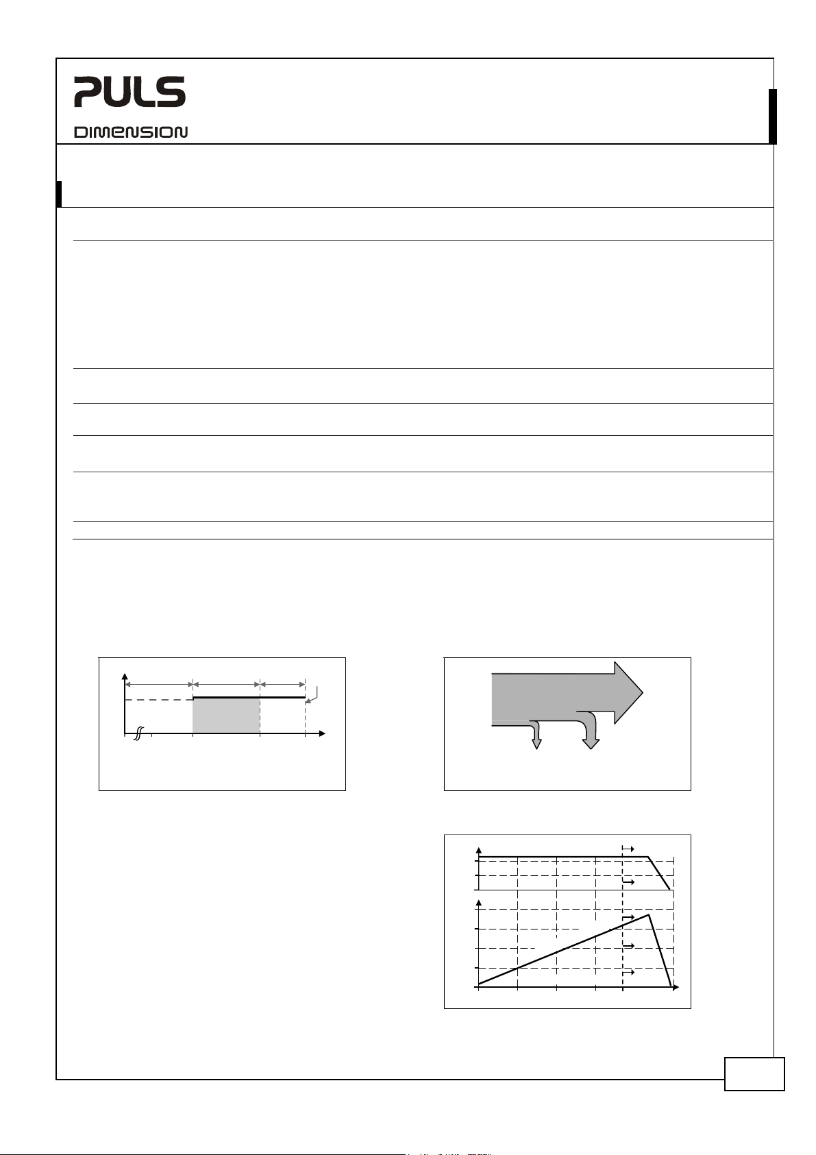
Fig. 5-1 Input voltage range Fig. 5-2 Input current, definitions
V
OUT
D
AB
nom. 22.5 to 30Vdc Continuous operation, see Fig. 5-1
35Vdc Absolute maximum input voltage with no damage to the
DC-UPS
0 to 22.5Vdc The DC-UPS switches into buffer mode and delivers
output voltage from the battery if the input was above
the turn-on level before and all other buffer conditions
are fulfilled.
max. 1.5Vpp Bandwidth <400Hz
max. 60Vdc or
42.4Vac
max.
22.8Vdc
23Vdc
The output does not switch on if the input voltage does
not exceed this level.
current mode at 24V input See Fig. 8-2 ***)
C
Input
Current
Output
Current
18 30 35V22.50
A: Rated input voltage range
B: Temp. allowed, no harm to the unit
C: Absolute max. input voltage
D: Buffer mode
V
IN
Internal
current
consumpt ion
Current
consumpt ion
for battery
charging
Electronic output current limitation
The DC-UPS is equipped with an electronic output
current limitation. This current limitation works in a
switching mode which reduces the power losses and
heat generation to a minimum. As a result, the
Fig. 5-3 Input current vs. 24V output current,
20V
10
typ. (battery fully charged)
Output Voltage
Overload
output voltage drops since there is not enough
current to support the load. A positive effect of the
current limitation in switching mode is that the input
current goes down despite an increase in the output
current resulting in less stress for the supplying
source. Fig. 5-3 shows the behavior when the 12V is
not loaded. Power which is taken out from the 12V
reduces the power on the 24V side.
20A
15
u
10
5
0
0
p
n
I
O
t
p
u
u
4812 20A
t
n
e
r
r
u
C
t
t
C
u
r
r
e
n
t
15
May. 2008 / Rev. 1.0 Datasheet DS-UB10.245-EN
All parameters are specified at an input voltage of 24V, 10A output load, 25°C ambient and after a 5 minutes run-in time
unless otherwise noted. It is assumed that the input power source can deliver a sufficient output current.
www.pulspower.com Phone +49 89 9278 0 Germany
3/24
U–Series
DC-UPS, DUAL OUTPUT
UB10.245
6. OUTPUT IN NORMAL MODE
The total output power of 360W can be shifted dynamically between the two outputs.
24V Output:
Output voltage
Voltage drop between input and
output
Ripple and noise voltage
Output current nom. 0 – 15A Continuously allowed, lower if the 12V output is loaded.
min. 12.3A Output if 12V output is loaded with 5A.
Short-circuit current
max. 21A
Capacitive and inductive loads No limitation
12V Output:
Output voltage
Output voltage tolerance ±2%
Ripple and noise voltage
Output current
Short-circuit current min. 4A
max. 5.5A
Capacitive and inductive loads No limitation
*) This figure shows the ripple and noise voltage which is generated by the DC-UPS. The ripple and noise voltage might be higher if
the supplying source has a higher ripple and noise voltage.
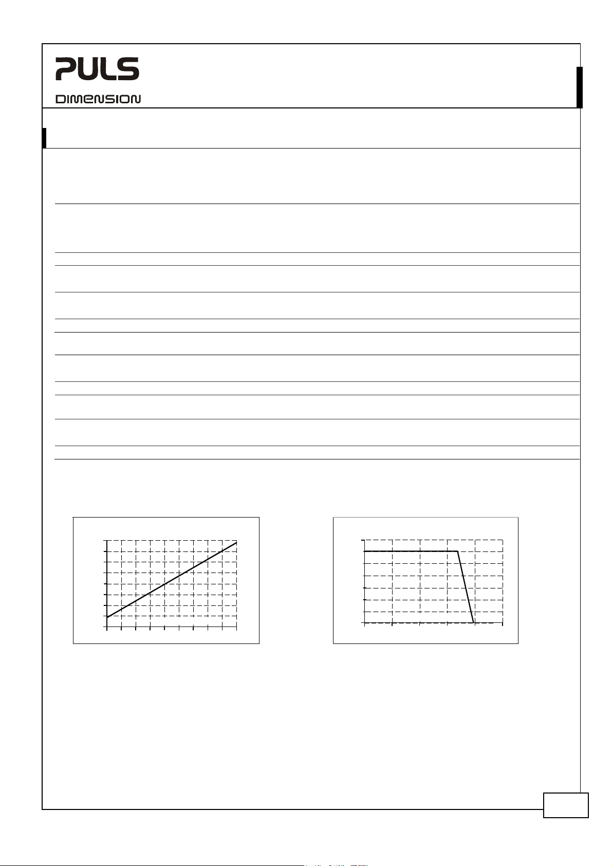
Fig. 6-1 Input to output voltage drop, typ.
Input to Output
Voltage drop
0.4V
0.35
0.3
0.25
0.2
0.15
0.1
0.05
0
02 10
4 6 8 12 14 16
u
p
t
u
O
nom. DC 24V The output voltage follows the input voltage reduced by the
input to output voltage drop.
max.
max.
0.3V
0.45V
At 10A output current, see Fig. 6-1 for typical values
At 15A output current, see Fig. 6-1 for typical values
max. 20mVpp 20Hz to 20MHz, 50Ohm *)
min. 17.9A
Load impedance 100mOhm, see Fig. 6-2 for typical values. The
12V output is off during an overload or short on the 24V.
nom. DC 12V
typ. 30mVpp 20Hz to 20MHz, 50Ohm *)
nom. 0 - 5A Continuously allowed, may be lower if the 24V output is loaded
more than 12.3A
Load impedance 100mOhm, see Fig. 7-5. for typical values. The
24V output is on during an overload or short on the 12V.
Fig. 6-2 Output voltage vs. output current in
normal mode at 24V input, typ.
Output Voltage
28V
24
20
t
n
r
e
r
u
C
t
18A
16
12
8
4
0
0 5 10 15 20
Output Current
25A
May. 2008 / Rev. 1.0 Datasheet DS-UB10.245-EN
All parameters are specified at an input voltage of 24V, 10A output load, 25°C ambient and after a 5 minutes run-in time
unless otherwise noted. It is assumed that the input power source can deliver a sufficient output current.
www.pulspower.com Phone +49 89 9278 0 Germany
4/24
U–Series
DC-UPS, DUAL OUTPUT
UB10.245
7. OUTPUT IN BUFFER MODE
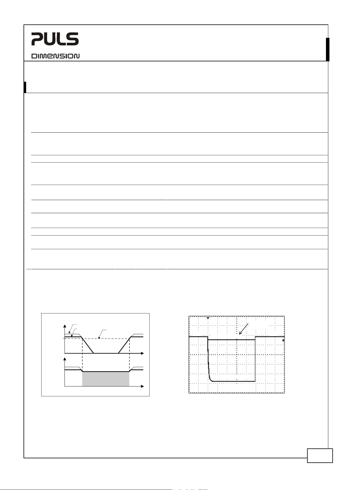
If the input voltage falls below the transfer threshold level, the DC-UPS starts buffering without any interruption or
voltage dips. The transfer threshold level is typically 80mV higher than the 24V output voltage in buffer mode.
Buffering is possible even if the battery is not fully charged.
24V Output
Output voltage
22.45V ±1%, at no load,
Ripple and noise voltage
Output current nom. 0 - 10A Continuously allowed, 12V output not loaded.
10 - 15A *) 12V output not loaded.
Short-circuit current
max. 21A
12V Output
Output voltage
Output voltage tolerance ±2%
Ripple and noise voltage
Output current
Short-circuit current min. 4A
*) If the output current is in the range between 10A and 15A (Bonus Power) for longer than 5s, a hardware controlled
reduction of the maximal output current to 10A occurs. If the 10A are not sufficient to maintain the 24V, buffering stops at
both outputs after another 5s. The buffering is possible again as soon as the input voltage recovers.
**) If the nominal output voltage cannot be maintained in buffer mode, the DC-UPS switches off after 5s to save battery
capacity.
Fig. 7-1 Buffering transition, definitions Fig. 7-2 Transfer behavior, typ.
nom. DC 24V Output is stabilized and independent from battery voltage
22.25V ±1%, at 10A output current
max. 20mVpp 20Hz to 20MHz, 50Ohm
min. 7.0A If 12V output is loaded with 5A.
min. 17.9A
Load impedance 100mOhm **); The 12V output is off during an
overload or short on the 24V.
nom. DC 12V Output is stabilized and independent from battery voltage
typ. 30mVpp 20Hz to 20MHz, 50Ohm ;
nom. 0 - 5A Continuously allowed, may be lower if the 24V output is loaded
more than 7.0A
Load impedance 100mOhm, see Fig. 7-5 for typical values.
max. 5.5A
Continuous constant; The 24V output is on during an overload
or short on the 12V as long as the battery delivers current.
O
u
t
p
u
t
o
V
a
l
t
g
e
4
2
V
V
I
Input
voltage
Output
voltage
28V
24V
Transfer
threshold
Buffer mode
4
2
V
2
2
.
5
2
V
a
t
1
0
A
t
t
e
l
a
g
o
t
u
V
n
I
0
t
V
p
m
/
s
D
0
0
5
May. 2008 / Rev. 1.0 Datasheet DS-UB10.245-EN
All parameters are specified at an input voltage of 24V, 10A output load, 25°C ambient and after a 5 minutes run-in time
unless otherwise noted. It is assumed that the input power source can deliver a sufficient output current.
www.pulspower.com Phone +49 89 9278 0 Germany
5/24

A
U–Series
Fig. 7-3 Available output current in buffer mode
Output
Current
15A
10A
BonusPower
®
5A
0
05 Sec.
Time
Fig. 7-4 24V Output voltage vs. output current in
Output Voltage
25V
20
15
10
5
0
0
Continuously available
A
Available for 5s then auto switching to curve
B
Buffering will stop after 5s
C
Buffering will stop after 5s
D
Fig. 7-5 12V Output voltage vs. output current in
normal or buffer mode, typ.
Output Voltage
14V
12
10
8
6
4
2
0
01 2 3
UB10.245
DC-UPS, DUAL OUTPUT
buffer mode, typ.
A B
CD
Output
Current
5101520
Output Current
45
6 A
25
D
May. 2008 / Rev. 1.0 Datasheet DS-UB10.245-EN
All parameters are specified at an input voltage of 24V, 10A output load, 25°C ambient and after a 5 minutes run-in time
unless otherwise noted. It is assumed that the input power source can deliver a sufficient output current.
www.pulspower.com Phone +49 89 9278 0 Germany
6/24

U–Series
DC-UPS, DUAL OUTPUT
UB10.245
8. BATTERY INPUT
The DC-UPS requires one 12V VRLA battery to buffer the 24V and 12V output.
Battery voltage
Battery voltage range
max. 35Vdc Absolute maximum voltage with no damage to the unit
Allowed battery sizes
max. 27Ah
Internal battery resistance
Battery charging method CC-CV Constant current, constant voltage mode
Battery charging current (CC-mode) nom. 1.5A Independent from battery size,
End-of-charge-voltage (CV-mode)
Battery charging time typ. 5h *) For a 7Ah battery
typ. 17h *) For a 26Ah battery
Battery discharging current **)
typ. 0.3A Buffer mode, 0A output current
Deep discharge protection ***) typ. 10.5V At 0% output load
typ. 9.0V At 100% output load
*) The charging time depends on the duration and load current of the last buffer event. The numbers in the table represent a
fully discharged battery. A typical figure for a buffer current of 10A at 24V output is 3h 20Min. for a 7Ah battery.
**) The current between the battery and the DC-UPS is more than twice the 24V output current. This is caused by boosting the 12V
battery voltage to a 24V level. This high current requires large wire gauges and short cable length for the longest possible
buffer time. The higher the resistance of the connection between the battery and the DC-UPS, the lower the voltage on the
battery terminals which increases the discharging current. See also chapter 25 for more installation instructions.
***) To ensure longest battery lifetime, the DC-UPS has a battery deep discharge protection feature included. The DC-UPS stops
buffering when the voltage on the battery terminals of the DC-UPS falls below a certain value.
Fig. 8-1 Battery discharging current
vs. 24V output current, typ.
(12V not loaded)
Battery Current
30A
25
20
15
10
5
0
0
2.5 7.5 10 15A12.55
O
t
p
u
u
t
u
r
C
e
n
r
nom. DC 12V Use one maintenance-free 12V VRLA lead acid battery or
one battery module which is listed in the chapter
accessories.
9.0 – 15.0V Continuously allowed, except deep discharge protection
typ. 7.4V Above this voltage level battery charging is possible
min. 3.9Ah
max. 100mOhm See individual battery datasheets for this value
max. 1.7A Corresponding 24V input current see Fig. 8-2
13.4-13.9V Adjustable, see chapter 14
typ. 21A Buffer mode, 240W output, 11.5V on the battery
terminal of the DC-UPS, see Fig. 8-1 for other parameters
max. 50μA At no input, buffering had switched off, all LEDs are off
typ. 310mA At no input, buffering had switched off, yellow LED
shows “buffer time expired” (max. 15 minutes)
Fig. 8-2 Required input current vs. input
voltage for battery charging
(12V not loaded)
Input Current
1.5A
1.25
1.0
m
a
x
.
(
b
a
t
t
e
r
y
c
ha
r
g
i
n
g
c
u
r
r
e
t
y
p
.
(
ba
t
t
e
r
y
c
h
a
r
g
n
i
n
g
c
ur
r
e
0.75
0.5
0.25
0
23
I
n
p
u
V
o
t
a
t
l
g
e
24 25 26 28V
27
t
1
.
7
A
)
n
t
1
.
5
A
)
A B C
Voltage on
battery terminal
of the DC-UPS:
A:
10.5V
B:
11V
C:
12V
t
May. 2008 / Rev. 1.0 Datasheet DS-UB10.245-EN
All parameters are specified at an input voltage of 24V, 10A output load, 25°C ambient and after a 5 minutes run-in time
unless otherwise noted. It is assumed that the input power source can deliver a sufficient output current.
www.pulspower.com Phone +49 89 9278 0 Germany
7/24

U–Series
DC-UPS, DUAL OUTPUT
UB10.245
9. BUFFER TIME
The buffer time depends on the capacity and performance of the battery as well as the load current. The diagram
below shows the typical buffer times of the 24V output with the standard battery modules at 20°C.
Buffer time with battery module UZK12.071 min. 18’30’’ At 5A output current *)
min. 5’30’’ At 10A output current *)
typ. 20’50’’ At 5A output current, see Fig. 9-1 **)
typ. 6’30’’ At 10A output current, see Fig. 9-1 **)
Buffer time with battery module UZK12.261 min. 96’30’’ At 5A output current *)
min. 37’50” At 10A output current *)
typ. 126’ At 5A output current, see Fig. 9-1 **)
typ. 53’20” At 10A output current, see Fig. 9-1 **)
*) Minimum value includes 20% aging of the battery and a cable length of 1.5m with a cross section of 2.5mm2 between the
battery and the DC-UPS and requires a fully charged (min. 24h) battery.
**) Typical value includes 10% aging of the battery and a cable length of 0.3m with a cross section of 2.5mm
and the DC-UPS and requires a fully charged (min. 24h) battery.
Buffer Current
10A
Fig. 9-1
8
6
4
2
Buffer time vs. 24V output current with the battery modules UZK12.071 and UZK12.261
U
Z
K
1
2
.
2
6
1
t
y
p
.
h
b
a
t
t
e
r
y
1
t
y
p
.
a
t
t
e
r
y
90
120 150 210 240
180 27090
U
U
Buffer Time (Minutes)
515
2010 25 30 35 45 5040 55 60 65 70 75 80 85
1
2
V
2
6
A
U
Z
K
1
2
.
0
7
1
2
V
7
A
h
b
2
between the battery
Z
K
1
2
.
2
6
1
t
y
p
.
Z
K
1
2
0
.
7
1
t
y
p
.
300
Min.
The buffer time is reduced if the 12V output is loaded. This can be calculated according to the following
example:
Example: 24V, 5A and 12V, 4A load
Step1: Convert the 12V current to a virtual 22.3V level:
Ratio: 12V/22.3V= 0.54 12V, 4A output converted to 22.3V level: 0.54*4A=2.15A
Step 2: Add the computed current to the actual 24V current:
2.15A+ 5A = 7.15A
Step 3: Determine the buffer time by using the standard buffer time curve (Fig. 9-1):
7.15A load with UZK12.071: Approx. 12 minutes buffer time.
The battery capacity is usually specified in amp-hours (Ah) for a 20h discharging event. The battery discharge is nonlinear (due to the battery chemistry). The higher the discharging current, the lower the appropriable battery capacity.
The magnitude of the reduction depends on the discharging current as well as on the type of battery. High current
battery types can have up to 50% longer buffer times compared to regular batteries when batteries will be
discharged in less than 1 hour. High discharging currents do not necessarily mean high power losses as the
appropriable battery capacity is reduced with such currents. When the battery begins to recharge after a discharging
May. 2008 / Rev. 1.0 Datasheet DS-UB10.245-EN
All parameters are specified at an input voltage of 24V, 10A output load, 25°C ambient and after a 5 minutes run-in time
unless otherwise noted. It is assumed that the input power source can deliver a sufficient output current.
www.pulspower.com Phone +49 89 9278 0 Germany
8/24

event, the process is completed much faster since only the energy which was taken out of the battery needs to be
“refilled”. For this reason, the buffer time cannot be calculated using the Ah capacity value.
The equation “I x t” = capacity in Ah generally leads to incorrect results when the discharging current is higher than
C20 (discharging current for 20h). The battery datasheet needs to be studied and a determination of the expected
buffer time can be made according to the following example:
Example how to determine the expected buffer time for other battery types and battery sizes:
Step 1 Check the datasheet of the battery which is planned to be used and look for the discharging curve.
Sometimes, the individual discharging curves are marked with relative C-factors instead of current
values. This can easily be converted. The C-factor needs to be multiplied with the nominal battery
capacity to get the current value. E.g.: 0.6C on a 17Ah battery means 10.2A.
U–Series
Fig. 9-2 Typical discharging curve of a typical 17Ah battery, curve taken from a
manufacturer’s datasheet
DC-UPS, DUAL OUTPUT
UB10.245
Step 2 Determine the required battery current. Use Fig. 8-1 “Battery discharging current vs. output current” to
get the battery current. Fig. 8-1 requires the average voltage on the battery terminals. Since there is a
voltage drop between the battery terminals and the battery input of the DC-UPS, it is recommended to
use the curve A or B for output currents > 3A or when long battery cables are used. For all other
situations, use curve C.
Step 3 Use the determined current from Step 2 to find the appropriate curve in Fig. 9-2. The buffer time
(Discharging Time) can be found where this curve meets the dotted line. This is the point where the DCUPS stops buffering due to the under-voltage lockout.
Step 4 Depending on Fig. 9-2, the buffer time needs to be reduced to take aging effects or guaranteed values
into account.
Example:
The buffer current is 24V 7.5A and a battery according Fig. 9-2 is used. The cable between the battery and the DC-UPS
is 1m and has a cross section of 2.5mm
Answer:
2
. How much is the maximum achievable buffer time.
According to Fig. 8-1, the battery current is 18A. Curve A is used since the battery current is > 3A and the
length of the cable is one meter.
According to Fig. 9-2, a buffer time (Discharging Time) of 30 Minutes can be determined. It is recommended
to reduce this figure to approximately 24 minutes for a guaranteed value and to cover aging effects.
May. 2008 / Rev. 1.0 Datasheet DS-UB10.245-EN
All parameters are specified at an input voltage of 24V, 10A output load, 25°C ambient and after a 5 minutes run-in time
unless otherwise noted. It is assumed that the input power source can deliver a sufficient output current.
www.pulspower.com Phone +49 89 9278 0 Germany
9/24

U–Series
DC-UPS, DUAL OUTPUT
UB10.245
10. EFFICIENCY AND POWER LOSSES
Efficiency typ. 97.5% Normal mode, 24V 10A, 12V 0A, battery fully charged
typ. 96% Normal mode, 24V 7.0A, 12V 5A, battery fully charged
Power losses typ. 3.4W Normal mode, no load, battery fully charged
typ. 6W Normal mode, 24V 10A, 12V 0A, battery fully charged
typ. 10W Normal mode, 24V 12.3A, 12V 5A, battery fully charged
typ. 5.5W During battery charging, no load.
typ. 19W Buffer mode, 24V 10A, 12V 0A
typ. 23W Buffer mode, 24V 7.0A, 12V 5A
11. FUNCTIONAL DIAGRAM
Fig. 11-1 Functional diagram
DC-UPS Control Unit
Input Fuse
24V
Power
Supply
12V Battery
+
-
Input
Battery
+
-
+
-
&
Reverse
Polarity
Protection
Battery
Tester
Cut-off
Relay
*
Battery
Charger
Electronic
Step-up
Converter
Current
Limiter
Step-down
Converter
Controller
+
24V Output
Buffered
Load
-
+
12V Output
Buffered
Load
-
Status LED (green)
Diagnosis LED (yellow)
Check Wiring LED (red)
Buffer-time Limiter
10s, 30s, 1m, 3m, 10m,
End-of-charge Voltage
(7)
Inhibit +
(8)
Inhibit -
(1) (2)
Ready
Contact
*) Return current protection; This feature utilizes a Mosfet instead of a diode in order to minimize the voltage drop and power
losses.
(3) (4)
Buffering
Contact
(5) (6)
Replace
Battery
Contact
May. 2008 / Rev. 1.0 Datasheet DS-UB10.245-EN
All parameters are specified at an input voltage of 24V, 10A output load, 25°C ambient and after a 5 minutes run-in time
unless otherwise noted. It is assumed that the input power source can deliver a sufficient output current.
www.pulspower.com Phone +49 89 9278 0 Germany
10/24
 Loading...