

UB10.241
– U Series
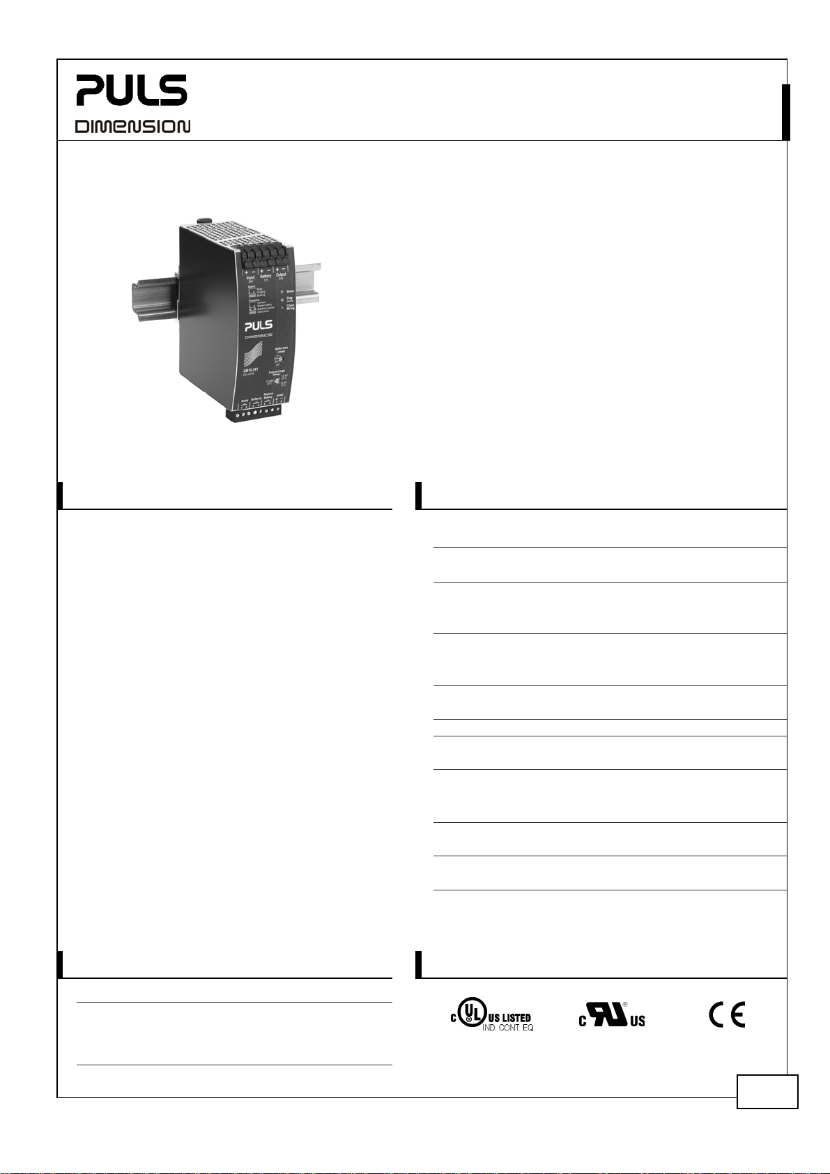
1. GENERAL DESCRIPTION
Power failures or voltage fluctuations can cause
damage and downtime, which usually costs a lot of
time and money. The UB10.241 together with a
battery module offers a reliable and economical
protection for 24V applications.
The output is isolated from the input, which allows
an easy separation of buffered and non-buffered
branches. The energy of the battery will not be
wasted by uncritical consumers.
In times when the power supply provides sufficient
voltage, the DC-UPS charges the 12V battery. In
case the input power fails, the battery voltage will
be boosted to a 24V level and the energy will be
released in a regulated process to the load.
The included battery management incorporates a
battery charger, a deep-discharge protection and
an overload protection to achieve a long service life
of the battery.
The availiability of the DC-UPS is reported by lamps
and relay contacts. The DC-UPS automatically
checks the installation, the battery fuse and the
quality and presence of the battery. Diagnosis is
very easy, thanks to clear understandable indicators
and relay contacts for remote signaling.
Extensive protection features protect the unit
against wrong battery polarity, wrong battery
voltage, wrong input oltage or output overloads.
24V, 10A
DC-UPS
■ Requires only one 12V battery
■ Regulated output voltage in buffer mode
■ Compact, width only 49mm
■ 50% power reserves
■ Low voltage drop between input and output
■ Electronically protected against output overloads
■ Extensive battery management including battery
quality and installation tests
■ Soft charger for optimum battery life
■ Extensive diagnostic and monitoring functions
■ Selectable buffer time limiter
■ 3 Year warranty
2. SHORT-FORM DATA
Operating voltage DC 24V
Voltage range 22.5-30Vdc
Output voltage
Voltage drop IN/OUT < 0.3V at 10A Normal mode
Output current 0 to 15A Normal mode
0 to 10A, cont. Buffer mode
0 to 15A, for 5s Buffer mode
Input current
Charging current typ. 1.5A into 12V battery
Charging time typ. 5h 12V, 7Ah battery
Cut-in threshold typ. 22.5V
Power losses 2.7W Standby mode
4.6W 10A, Normal mode
Buffer time min. 6’ 15’’ at 10A, 7Ah battery
typ. 8’ 30’’
typ. 32’ at 4A, 7Ah battery
Allowed batteries >3.9Ah, VRLA batteries
< 27Ah
Temperature range -25°C…+60°C operational
Derating 0.25A/°C +60 to +70°C
Dimensions 49x124x117mm
Weight 530g
*)
add output current to calculate the total input current
±2%
22.4V
typ. 0.12A *)
max. 1.1A *)
Buffer mode
Standby mode
Charging mode
at 10A, 7Ah battery
WxHxD
3. ORDER NUMBERS
DC-UPS
Accessory UZK12.07 12V, 7Ah Battery module
ZM1.WALL Wall mounting bracket
March 2006 / Rev. 0.2 / DS-UB10.241-EN / All parameters are specified at 24V, 10A and 25°C ambient unless otherwise noted.
UB10.241
24V, 10A
www.pulspower.com Phone +49 89 9278 0 Germany
4. MARKINGS
pending
pending
EMC, LVD
1/11

UB10.241
– U Series
24V, 10A
INDEX PAGE INDEX PAGE
1. General Description .................................... 1
2. Short-form Data .......................................... 1
3. Order Numbers............................................ 1
4. Markings ...................................................... 1
5. Functional Diagram..................................... 3
6. Wiring Instructions......................................3
7. Required Settings before Use..................... 4
8. Buffer Time.................................................. 4
9. Front Side and User Elements..................... 5
10. Battery Quality Test .................................... 6
11. Check Wiring Test ....................................... 6
12. Relay Contacts and Inhibit Input ............... 6
13. Terminals and Wiring ................................. 7
14. Reliability..................................................... 8
15. EMC.............................................................. 8
16. Environment................................................ 9
17. Protection Features..................................... 9
18. Safety ......................................................... 10
19. Approvals................................................... 10
20. Fulfilled Standards .................................... 10
21. Physical Dimensions and Weight ............. 11
22. Installation Notes...................................... 11
TERMINOLOGY AND ABREVIATIONS
Normal Mode Describes a condition where the battery is fully charged, the input voltage is in range and the
output is loaded within the allowed limits.
Buffer Mode Describes a condition where the input voltage is below the cut-in threshold, the unit is buffering
and the output is loaded within the allowed limits.
Charging Mode Describes a condition where the battery is charging, the input voltage is in range and the output
is loaded within the allowed limits.
DISCLAIMER
The information presented in this document is believed to be accurate and reliable and may change without notice.
March 2006 / Rev. 0.2 / DS-UB10.241-EN / All parameters are specified at 24V, 10A and 25°C ambient unless otherwise noted.
www.pulspower.com Phone +49 89 9278 0 Germany
2/11
UB10.241
– U Series
24V, 10A
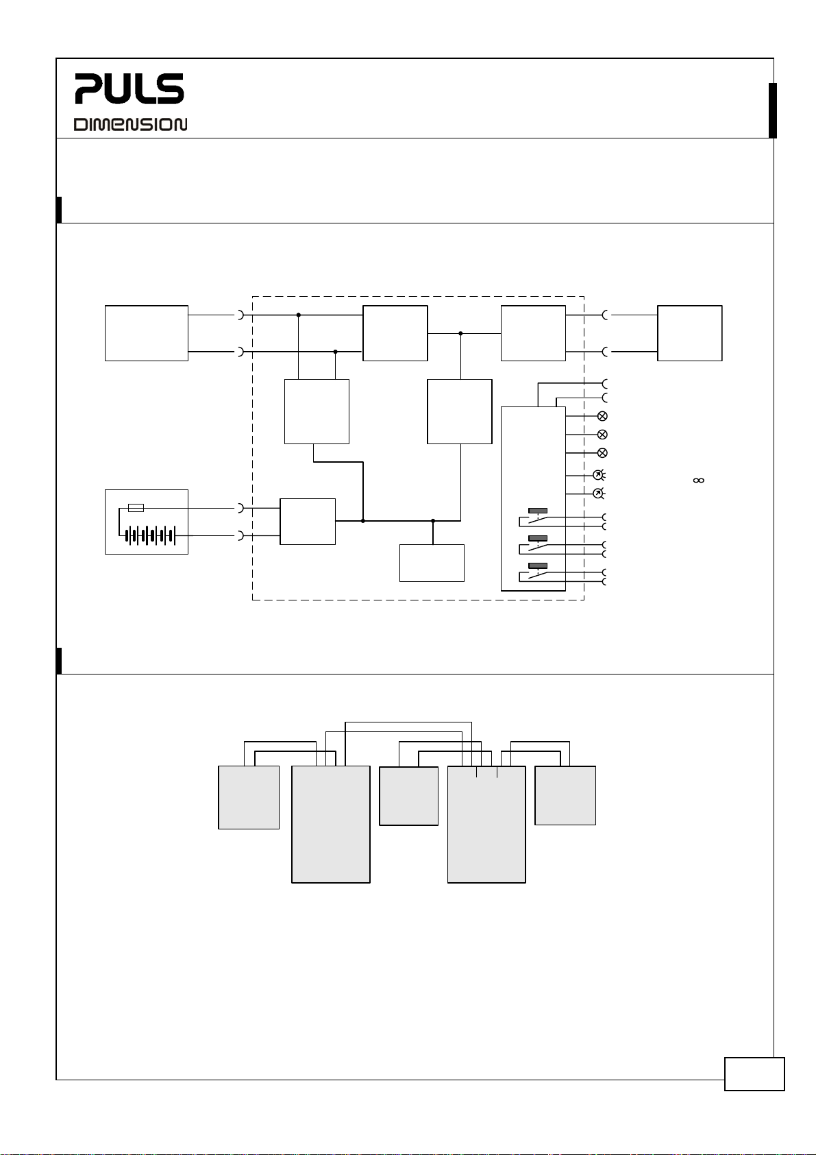
5. FUNCTIONAL DIAGRAM
Fig. 5-1 Functional diagram
DC- UPS
+
Buffered
-
(7)
Inhibit +
(8)
Inhibit -
Status LED
Diagnosis LED
Check Wiring LED
Buffer Time Limiter
10s, 30s, 1m, 3m, 10m,
End-of-Charge Voltage
(1)
Ready Contact
(2)
(3)
Buffering Contact
(4)
(5)
Replace Battery
(6)
Load
(green)
(yellow)
12V Battery
24V
Power
Supply
+
+
Input /
Input Output
-
Battery
Charger
Output
Isolator
Boost
Converter
Electronic
Current
Limiter
Controller
+
Battery
-
-
Safety
Relay
Battery
Tester
(red)
6. WIRING INSTRUCTIONS
Fig. 6-1 Wiring diagram
-
+
-
Un-
critical
Load
+-+
Output
Power
Supply
Input
NL
-
PE
+
-
12V
Battery
+-+
-
+
IN
OUT
BAT
24V
24V
12V
UB10.241
DC-UPS
Signal Port
-
a) Connect the power supply to the „Input“ terminals of the DC-UPS
b) Connect either a 12V VRLA battery with a capacity between 3.9 and 27Ah or our battery module
UZK12.07 to the “Battery” terminals of the DC-UPS. Use wires not smaller than 2.5mm
and not longer than 1.5m (single length). Use a 30A fuse Typ ATO® 257 030 (Littelfuse) or the like.
The battery fuse protects the wires between the battery module and the DC-UPS. Furthermore, it
allows the disconnection of the battery from the DC-UPS, which is recommended, when working on
the battery or DC-UPS.
c) Connect the buffered load to the “Output” terminals of the DC-UPS. Uncritical loads can be
connected directly to the power supply.
+
Buffered
Load
2
(or 12 AWG)
March 2006 / Rev. 0.2 / DS-UB10.241-EN / All parameters are specified at 24V, 10A and 25°C ambient unless otherwise noted.
www.pulspower.com Phone +49 89 9278 0 Germany
3/11
UB10.241
– U Series
24V, 10A
7. REQUIRED SETTINGS BEFORE USE
Setting the buffering timer:
The unit is equipped with a buffering timer, which limits the max. buffer time to save battery capacity. The rotary
switch on the front allows the setting of a timer to the following 6 steps:
- Indefinite timer deactivated, buffering until the deep discharge protection stops the buffer mode.
- 10 Seconds
- 30 Seconds
- 1 Minute
- 3 Minutes
- 10 Minutes
If the DC voltage recovers within this period of time, the buffering stops immediately.
Setting the end-of-charge voltage:
The end-of-charge voltage depends on the battery temperature and has a major influence on the life of the battery.
The potentiometer on the front of the unit allows an adjustment of the expected battery temperature:
10°C end-of-charge voltage 13,92V ±0,1V
20°C end-of-charge voltage 13,74V ±0,1V
30°C end-of-charge voltage 13,56V ±0,1V
40°C end-of-charge voltage 13,38V ±0,1V
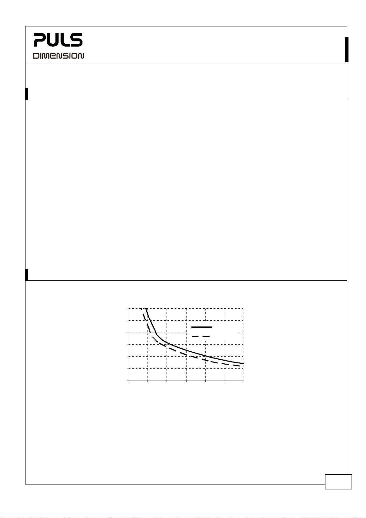
8. BUFFER TIME
Fig. 8-1 Hold-up time vs. output current with the battery module UZK12.07 (12V, 7,5Ah)
12A
10A
8A
6A
4A
2A
0A
0min 5min 10min 15min 20min 25min 30min
(1) typ.
(2) min.
March 2006 / Rev. 0.2 / DS-UB10.241-EN / All parameters are specified at 24V, 10A and 25°C ambient unless otherwise noted.
www.pulspower.com Phone +49 89 9278 0 Germany
4/11

UB10.241
– U Series
9. FRONT SIDE AND USER ELEMENTS
Power Port
Quick-connect spring-clamp
terminals. Connections for:
Input voltage
Battery and
Output voltage.
The green LED shows the status of the DC-UPS
Ready: Battery is charged > 85%, no wiring failure is recognized,
input voltage is sufficient and inhibit signal is not active.
Charging: Battery is charging, battery capacity is below 85%
Buffering: Unit is in buffer mode
Flashing pattern of the
green status LED:
The yellow diagnosis LED displays warnings and gives further
information about the DC-UPS.
Overload: Output has switched off, due to long overload in
buffer mode or due to too high temperatures
Replace battery: Indicates a battery, which failed the battery
quality test (SOH test) Battery shall be replaced soon.
Buffer-time expired: Output has switched off, due to settings
of buffer timer or due to the deep discharge protection. The
signal will be stored and displayed for 15 minutes.
Inhibit active: Indicates that buffering is disabled, due to an
active inhibit signal.
Flashing pattern of the
yellow diagnosis LED:
24V, 10A
1
0
1
0
1
0
1
0
1
0
1
0
1
0
Ready
Charging
Buffering
Overload
Replace
Battery
Buffertime
expired
Inhibit
active
The red check wiring LED indicates a failure in the installation, wiring,
battery or battery fuse.
Buffer time limiter:
User accessible switch, which limits the maximum buffer time in a buffer
event to save battery capacity.
End-of-charge voltage:
User accessible potentiometer to set the end-of-charge voltage. Adjust the
potentiometer according to the expected battery temperature.
Signal Port
Plug Connector inserted from the bottom. Connections for:
Ready relay contact (1-2)
Buffering relay contact (3-4)
Replace Battery relay contact (5-6)
Inhibit input signal (7-8)
March 2006 / Rev. 0.2 / DS-UB10.241-EN / All parameters are specified at 24V, 10A and 25°C ambient unless otherwise noted.
www.pulspower.com Phone +49 89 9278 0 Germany
5/11

UB10.241
– U Series
24V, 10A
10. BATTERY QUALITY TEST
The quality of the battery will be checked periodically. A negative result (usually caused by aged batteries) will be
displayed with a special blinking pattern on the yellow diagnosis LED on the front of the unit.
Once the battery quality test indicates a bad quality of the battery, it is recommended to change the battery as soon
as possible
A replacement for the battery can be ordered from PULS under UZB12.07.
11. CHECK WIRING TEST
The wiring between the battery and the DC-UPS will be checked periodically. In case of a loose connection, a
defective wire, a defective fuse, a wrong battery, a fatal failure of the battery or a reverse battery polarity will be
displayed with the red “Check Wiring” LED on the front of the unit.
12. RELAY CONTACTS AND INHIBIT INPUT
Ready Relay (Pin 1&2)
Buffering Relay (Pin 3&4) Contact is closed when unit is buffering.
Replace Battery (Pin 5&6)
Relay contact ratings max 60Vdc 0.3A, 30Vdc 1A, 30Vac 0.5A resistive load
min 1mA at 5Vdcmin.
Isolation voltage max 500Vac, signal port to power port
Inhibit input (Pin 7&8)
Signal voltage max. 35Vdc
Signal current max. 4mA, current limited
Inhibit threshold min. 6Vdc, buffering is enabled above this threshold level
max. 10Vdc
Isolation nom. 500Vac, signal port to power port
Contact is closed when battery is charged more than 85%, no wiring failure is
recognized, input voltage is sufficient and inhibit signal is not active.
Contact is closed when input voltage is sufficient and battery quality test (SOH
test) indicates that the battery should be replaced.
The inhibit input disables buffering. In normal mode, a
static signal is required.
In buffer mode, a pulse with a minimum length of
250ms is required to stop buffering. The inhibit is
stored and can be reset by cycling the input voltage.
7 +
3mA
Inhibit
5,1V
8 -
March 2006 / Rev. 0.2 / DS-UB10.241-EN / All parameters are specified at 24V, 10A and 25°C ambient unless otherwise noted.
www.pulspower.com Phone +49 89 9278 0 Germany
6/11

UB10.241
– U Series
24V, 10A
13. TERMINALS AND WIRING
Power terminals
Type Bi-stable, quick-connect spring clamp terminals. IP20 Finger safe construction.
Suitable for field- and factory installation. Shipped in open position.
Solid wire 0.5-6mm
Stranded wire 0.5-4mm2
AWG 20-10AWG
Ferrules Allowed, but not required
Pull-out force 10AWG:80N, 12AWG:60N, 14AWG:50N, 16AWG:40N (according to UL486E)
Wire stripping length 10mm / 0.4inch
Fig. 13-1 Connecting a wire
Instructions:
a) Use appropriate copper cables, that are designed
for an operating temperature of 60°C
b) Follow national installation codes and regulations!
c) Ensure that all strands of a stranded wire enter the
terminal connection!
d) Up to two stranded wires with the same cross
section are permitted in one connection point
2
1. Insert the wire 2. Snap the lever
To disconnect wire: same procedure vice versa
Signal terminals
Type Plug connector with screw terminal mechanism.
Finger-touch-proof terminal with captive screws for 3.5mm slotted screwdriver.
Solid / stranded wire
AWG 22-14AWG
Ferrules
Wire stripping length 6mm / 0.24inch
Tightening torque 0.4Nm, 3.5lb.in
0.2-1.5mm2
up to 1.5 mm
2
wire gauge
March 2006 / Rev. 0.2 / DS-UB10.241-EN / All parameters are specified at 24V, 10A and 25°C ambient unless otherwise noted.
www.pulspower.com Phone +49 89 9278 0 Germany
7/11

UB10.241
– U Series
24V, 10A
14. RELIABILITY
Lifetime expectancy min. T.b.d. 40°C, normal mode
min. T.b.d. 25°C, normal mode
MTBF SN 29500, IEC 61709 T.b.d. 40°C, normal mode
T.b.d. 25°C, normal mode
T.b.d. 40°C, buffer mode
T.b.d. 25°C, buffer mode
MTBF MIL HDBK 217F T.b.d. 40°C, normal mode, ground benign GB40
T.b.d. 25°C, normal mode, ground benign GB25
T.b.d. 40°C, buffer mode, ground benign GB40
T.b.d. 25°C, buffer mode, ground benign GB25
The Lifetime expectancy shown in the table indicates the operating hours (service life) and is determined by the
lifetime expectancy of the built-in electrolytic capacitors. Lifetime expectancy is specified in operational hours.
Lifetime expectancy is calculated according to the capacitor’s manufacturer specification.
MTBF stands for Mean Time Between Failure, which is calculated according to the statistically device failures, and
indicates reliability of a device. It is the statistical representation of the likelihood of a unit to fail and does not
necessarily represent a life of a product.
15. EMC
The unit is suitable for applications in industrial environment as well as in residential, commercial and light industry
environment without any restrictions. CE mark is in conformance with EMC guideline 89/336/EEC and 93/68/EEC and
the low-voltage directive (LVD) 73/23/EWG.
A detailed EMC Report is available on request
EMC Immunity
Electrostatic discharge 1) EN 61000-4-2 Contact discharge
Electromagnetic RF field EN 61000-4-3 80MHz-1GHz 10V/m Criterion A
Fast transients (Burst) EN 61000-4-4 2kV Criterion A
Surge voltage EN 61000-4-5 + -
Conducted disturbance EN 61000-4-6 0,15-80MHz 10V Criterion A
1) Din-Rail earthed
EMC Emission
Conducted emission EN 55022 Class B
Radiated emission EN 55011, EN 55022 Class B
This device complies with FCC Part 15 rules.
Operation is subjected to following two conditions: (1) this device may not cause harmful interference, and (2) this
device must accept any interference received, including interference that may cause undesired operation.
EN 61000-6-1 EN 61000-6-2
Air discharge
+ / - housing
EN 61000-6-3 and EN 61000-6-4 Generic standards
Generic standards
8kV
15kV
500V
500V
Criterion A
Criterion A
Criterion A
Criterion A
March 2006 / Rev. 0.2 / DS-UB10.241-EN / All parameters are specified at 24V, 10A and 25°C ambient unless otherwise noted.
www.pulspower.com Phone +49 89 9278 0 Germany
8/11

UB10.241
– U Series
24V, 10A
16. ENVIRONMENT
Operational temperature -25°C to +70°C full power, for the DC-UPS control unit, keep
Derating 0,25A/°C +60°C…+70°C, buffer mode see
0,43A/°C +60°C…+70°C, normal mode see
Storage temperature -40 to +85°C storage and transportation, except battery
Humidity 5 to 95% r.H. IEC 60068-2-30
Vibration sinusoidal 2-17.8Hz: ±1.6mm; 17.8-500Hz: 2g IEC 60068-2-6
Vibration random 0.5m2(s3) IEC 60068-2-64
Shock 30g 6ms, 20g 11ms IEC 60068-2-27
Altitude 0 to 6000m Approvals apply only up to 2000m
Over-voltage category III EN 50178
II EN 50178 above 2000m altitude
Degree of pollution 2 EN 50178, not conductive
Fig. 16-1 Output current in normal mode vs.
Max. Output
Current at 24V
15A
12.5
7.5
2.5
ambient temp.
10
5
0
-25 0 20 40
Ambient Temperature
n
c
o
t
i
n
u
o
u
s
70°C
60
Max. Output
Current at 24V
The ambient temperature is defined 2cm below the unit.
battery in a cold environment!
Do not energize while condensation is present
Fig. 16-2 Output current in buffer mode vs.
15A
12.5
10
7.5
5
2.5
0
-25 0 20 40
ambient temp.
r
f
o
p
t
y
c
o
t
n
u
i
n
Ambient Temperature
5
.
s
s
u
o
70°C
60
Fig. 16-2
Fig. 16-1
17. PROTECTION FEATURES
Output protection Electronically protected against overload, no-load and short-circuits
Output over-voltage protection
in buffer mode
Degree of protection IP 20 EN/IEC 60529
Penetration protection > 3.5mm e.g. screws, small parts
Reverse battery polarity protection yes max. –35Vdc
Wrong battery voltage protection yes max. +35Vdc (e.g. 24V instead of 12V)
Battery deep discharge protection yes limit is battery current dependent
Over temperature protection yes output shut-down with automatic restart
Input over-voltages protection yes max. 35Vdc, no harm or defect of the unit
Internal input fuse 20A no user accessible part, no service part
March 2006 / Rev. 0.2 / DS-UB10.241-EN / All parameters are specified at 24V, 10A and 25°C ambient unless otherwise noted.
typ. 32Vdc
max. 35Vdc
In case of an internal defect, a redundant circuitry
limits the maximum output voltage. The output
automatically shuts-down and makes restart attempts.
www.pulspower.com Phone +49 89 9278 0 Germany
9/11

UB10.241
– U Series
24V, 10A
18. SAFETY
Output voltage SELV IEC/EN 60950-1
PELV EN 60204-1, EN 50178, IEC 60364-4-41
Class of protection II
Isolation resistance > 5MOhm Power port to housing, 500Vdc
PE resistance < 0.1Ohm between housing and chassis ground terminal
Dielectric strength 500Vac Power port to signal port
500Vac Power port / signal port to housing
19. APPROVALS
UL 508
pending
UL 60950-1
pending
IEC 60950-1
pending
Marine
pending
18WM
IND. CONT. EQ.
IECEE
CB SCHEME
GL
ABS
LISTED E198865 listed for use in U.S.A. (UL 508) and
Canada (C22.2 No. 14-95)
Industrial Control Equipment
RECOGNIZED E137006 recognized for the use in
U.S.A. (UL 60950-1) and Canada (C22.2 No. 60950)
Information Technology Equipment, Level 5
CB Scheme,
Information Technology Equipment
GL (Germanischer Lloyd) classified and ABS (American Bureau for
Shipping) PDA for marine and offshore applications.
Environmental category: C, EMC2
20. FULFILLED STANDARDS
EN/IEC 60204-1 Safety of Electrical Equipment of Machines
EN/IEC 61131 Programmable Controllers
EN 50178 Electronic Equipment in Power Installations
March 2006 / Rev. 0.2 / DS-UB10.241-EN / All parameters are specified at 24V, 10A and 25°C ambient unless otherwise noted.
www.pulspower.com Phone +49 89 9278 0 Germany
10/11

UB10.241
– U Series
21. PHYSICAL DIMENSIONS AND WEIGHT
Width 49mm / 1.93’’
Height 124mm / 4.88’’ plus height of signal connector
Depth 117mm / 4.61’’ plus depth of DIN-rail
Weight 530g / 1.17lb
DIN-Rail Use DIN-rails according to EN 60715 or EN 50022 with a height of 7.5 or 15mm
Fig. 21-1 Side view Fig. 21-2 Front view
24V, 10A
22. INSTALLATION NOTES
Cable to connect the battery
Use wires not smaller than 2.5mm2 (or 12 AWG) and not longer than 2x1.5m. Use a 30A battery fuse typ ATO® 257
030 (Littelfuse) or the like. The battery fuse protects the wires between the battery module and the DC-UPS.
Furthermore, it allows the disconnection of the battery from the DC-UPS, which is recommended, when working on
the battery or DC-UPS.
Mounting orientation
The power terminal shall be located on top of the unit.
Cooling
Convection cooled, no forced air cooling required. Do not obstruct air flow!
Installation clearances:
No special installation clearances are necessary
Intended use
This DC-UPS has been designed for use in panel board installations or other building-in applications where a suitable
mechanical enclosure shall be provided to fulfil local requirements.
Service parts:
The unit does not contain any service parts. If damage or malfunctioning should occur during operation, immediately
turn power off and send unit for inspection to factory!
March 2006 / Rev. 0.2 / DS-UB10.241-EN / All parameters are specified at 24V, 10A and 25°C ambient unless otherwise noted.
www.pulspower.com Phone +49 89 9278 0 Germany
11/11
 Loading...