

Page 1
AS-Interface
Power Supply with 8A
SLA8.100
• Input: AC 115V / 230V
• Output: 30.55V / 8A
• AS Interface data decoupling
• Infrared (IR) addressing mode
• Overload protection by FUSE Mode
• For highly demanding industrial
applications
Data sheet
Short description
Appr. No. 41601
EMC and
Low Volt.
Directive
UL60950 E137006
CUL/CSA-C22.2
No. 60950
UL508 LISTED
IND. CONT. EQ.
18 WM, 60°C
CB
scheme
IEC60950
Data and energy:
The primary switched mode DIN rail power supply SLA8.100 specifically
supplies AS Interface
logy allows to connect up to 62 participants to a control and to supply
them with energy with a single two-conductor cable. When connecting
slaves, the yellow AS-Interface cable offers the high degree of protection
IP67 in conjunction with the insulation displacement. The communication signals of the individual network participants are modulated onto
the supply voltage. For this purpose, specific power supply units with integrated data decoupling are required for AS-Interface systems.
Fast addressing of slaves:
The "IR addressing mode" selectable via jumper interrupts the data communication on the yellow AS-Interface cable. Participants with an infrared interface can then quickly be assigned a new ID address by means of
an infrared programming unit without the need to disconnect them
from the AS-Interface cable. Afterwards, the "Communication Mode"
®
systems with energy. The AS-Interface bus techno-
Input
Rated voltage AC100-120/220-240V
(selectable by front panel slide switch)
Rated current 6.0A (switch in 115V position)
2.8A (switch in 230V position)
Frequency 47...63 Hz (alternatively also DC possible)
Voltage range AC 85...132V/184...264V, DC 230...375V
Power factor >0.5
Integrated internal
fuse
Inrush current Limited by NTC resistor
Peak current I
2
t <1.0A2s <1.5A2s<1.4A2s<1.6A2s
I
Hold-up time >10ms @ AC 100V or AC 196V and rated load
pk
T8A/250V HBC (ot accessible)
(bypassed by a relay during normal operation)
T
= +50°C, cold start
amb
(line impedence acc. EN 61000-3-3)
AC 100V AC 120V AC 220V AC 240V
<12A <14A <24A <27A
(also see diagram)
can be selected again to re-start the data communication.
Safe operation by FUSE Mode:
The device features a FUSE Mode, which permanently switches off the
output in the event of failure and the unit at overload, short-circuit or
overtemperature and thus protects the relatively thin AS-Interface line
and the attached components. Triggering of the FUSE Mode is indicated
by a flashing LED. System restart requires the intentional activation of a
reset button on the front side of the unit. Thus, an accidental restart is
prevented and the slaves are protected against damage.
Fit for the world market:
The input voltage range of the unit can be selected on the front panel.
Thus, it can be operated worldwide on all usual single-phase line voltages. International (IEC 60950) and various national (CBscheme) approvals
allow for worldwide application.
Output
Rated voltage DC 30.55V ±3% (not adjustable)
Rated current 8.0A
Isolation Safe low voltage PELV (IEC364-4-41)
Current limitation >8.4A
Overload behaviour FUSE Mode (2...5s continuous current, after-
wards permanent switch-off)
Short-circuit current >12A <25A (max. 5s)
Load regulation stat. <200mV (no load / full load)
Line regulation stat. <30mV (AC 85...132V/184...264V)
Ripple 50mV
Noise (Spikes) 100mV
Overvoltage protection limited to max. 55V
Operating indicator Green LED (extinguishes at overload)
Output is protected against short-circuit, open circuit and overload.
Use AS-Interface power supplies only together with AS-Interface lines!
(500kHz bandw., 50Ω measurem.,
PP
ohmic load)
(20MHz bandw., 50Ω measurem.,
PP
ohmic load)
SELV (IEC60950)
Order information
Order number Description
SLA8.100
SLZ13
SLZ02
sla8e100 / 040225 1/4
AS-Interface power supply unit
Adapter for S7-300 rail
Wall mounting set (two pcs. per package)
Page 2
SLA8.100Data sheet
FUSE Mode
The FUSE Mode (electronic fuse in the output) protects the unit from
overload and overtemperature.
Shutdown:
• At overtemperature, overload or short-circuit (8.4A < I
the unit switches off the output after 2...5s
Indicator:
• Activation of the FUSE Mode is indicated by a flashing red LED
Reset / Restart:
• by intentionally pushing the Reset button on the unit front panel
• by turning off the mains voltage. Before restarting the unit, wait at
least twice the time the flashing red LED needed to extinguish after
the mains voltage dropped.
max
< 12A),
Operating and environmental data
Non-operating
temperature range
Operating
temperature range
Derating from 60°C 6W/°C onwards, power reduction
Cooling natural convection,
Over-temperature
protection
Humidity protect from moisture and condensation
Vibration
• Sinus
•Random
Shock 15g (6ms), 10g (11ms), (IEC 68-2-27)
Degree of pollution 2 (EN 60950)
Overvoltage category III (EN 50178)
-25°C...+85°C
-10°C...+70°C
(measured at 25mm below the unit)
necessary (see diagram)
no forced air-cooling necessary
implemented
2 – 17.8Hz ±1.6cm
17.8Hz – 500Hz 2g (IEC 68-2-6)
2...800Hz 0.5m
2
(s3) (IEC 68-2-64)
Electromagnetic Compatibility (EMC)
Emissions EN 50081-2 Class B (EN 55011, EN 55022)
Immunity
• Electrostatic
Discharge (ESD)
• Electromagnetic
radiated fields
• Burst, coupled to:
– ACin lines
– DCout lines
• Surge transients
– Differential
mode (L→PE)
– Common mode
(L
→ N)
• Conducted noise
immunity
• Voltage dips EN 61000-4-11
•Transient
immunity
Efficiency, Reliability
Efficiency typ. 92% (AC 230V, 8A)
Power dissipation typ. 21.2W (AC 230V, 8A)
EN 61000-6-2 (also includes EN 55024)
EN 61000-4-2, Level 4
(withstands 8kV direct discharge,
15kV air discharge)
EN 61000-4-3, Level 3 (10V/m)
ENV 50204 (10V/m)
EN 61000-4-4,
Level 4 (4 kV)
Level 3 (2 kV)
EN 61000-4-5,
Installation class 4 (4kV)
Installation class 4 (2kV)
EN 61000-4-6,
Level 3 (10V, 150kHz - 80MHz)
Transient resistance acc. to VDE 0160 / W1
across entire load range
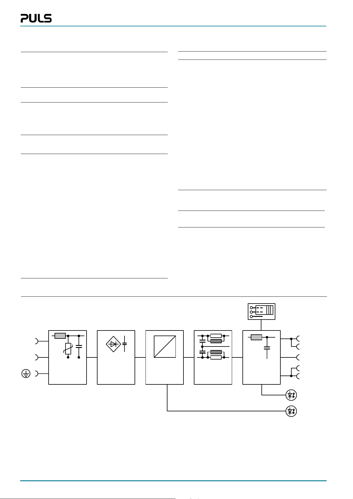
Schematic
L
N
V
Transient-
Inrush- and
EMC- Filter
Input Rectifier
and Hold-up
Capacitor
DC
DC
DC to DC
Converter
AS-i
Decoupling
Network
Infrared (IR)
Addressing
Mode
Mode Selector:
Communication/
IR Addressing
AS-i +
AS-i +
Shield
AS-i -
AS-i -
IR on
AS-i ok
2/4 sla8e100 / 040225
Page 3
Operating indicators and elements
115/230V switch:
Slide switch to select the
input voltage range
Plastic slider
Data sheet
Red LED:
flashes when FUSE Mode
has been triggered
Reset Button:
Push to reset the
FUSE Mode
Red LED:
• ON: Jumper pos. 2-3
• OFF: Jumper pos. 1-2
Plug-in jumper:
• Pos. 1-2: regular AS-Interface communication
• Pos. 2-3: Data communication is interrupted. IRaddressing can be carried
out
SLA8.100
102
93
Plastic slider:
• Mounting: Place the unit onto the
DIN-rail and push it downwards and
against the lower front edge until it
snaps into place.
• Detachment: Push downwards and
detach the unit from its DIN-rail
mounting bracket.
DIN-rail mounting bracket
2
6
2
6
Green LED:
• ON: AS-Interface voltage
is within the limits.
• OFF: at overload or missing input voltage
Input terminals
Output terminals:
Dual terminals for
AS-Interface + und
Connection machine
ground
AS-Interface –
Connectors and terminals
Terminals Fingertouch-proof terminals with captive
Position Easy to reach terminals on the front panel;
Tightening torque 0.8Nm
Connector size range
• flexible cable
• solid cable
Ferrules admissible
Stripping length 7mm
screws for 5.5mm slotted screwdriver or Philips
cross-recessed screwdriver No. 2
input and output clearly separate from each
other
0.5-4mm
0.5-6mm
2
(20-10AWG)
2
(20-10AWG)
Front elements
PE terminal
N Input neutral
L Input phase
brown
blue
Shield Connection of machine ground.
Positive AS-Interface output voltage (twice)
Negative AS-Interface output voltage (twice)
(Functional earth for balancing the AS-Interface output. Connection is recommended for
EMC)
4
Construction / Mechanics
Housing Robust metal housing for built-in installation
Degree of protection IP20 (EN 60529)
Class of protection 1 (IEC536);
do not use without protective earth (PE)
Width w
Height h
Depth d
91mm
124mm
102mm (without DIN rail)
Weight appr. 890g
Installation notes
External fusing • not necessary (internal fuse)
Mounting position vertical; input below, output above
Free space for cooling above / below 25mm recommended
Always connect PE before operating the unit!
Operation without AS-Interface: This AS-Interface PSU has an inductive output. When operating without AS-Interface structure (e.g. in
a laboratory test) you should connect a 470µF / 35V capacitor between
AS-Interface + and AS-Interface – as commercial electronic loads in
combination with the data decoupling often tend to oscillate, and the
oscillation may exceed the permitted modulation voltage. Otherwise,
equipment may be destroyed.
• observe national regulations
• circuit breaker with B-characteristic min. 6A
or slower action, or alternatively 6A HBC
fuse
left / right 15mm recommended
5
sla8e100 / 040225 3/4
Page 4
Functional diagrams
Data sheet
SLA8.100
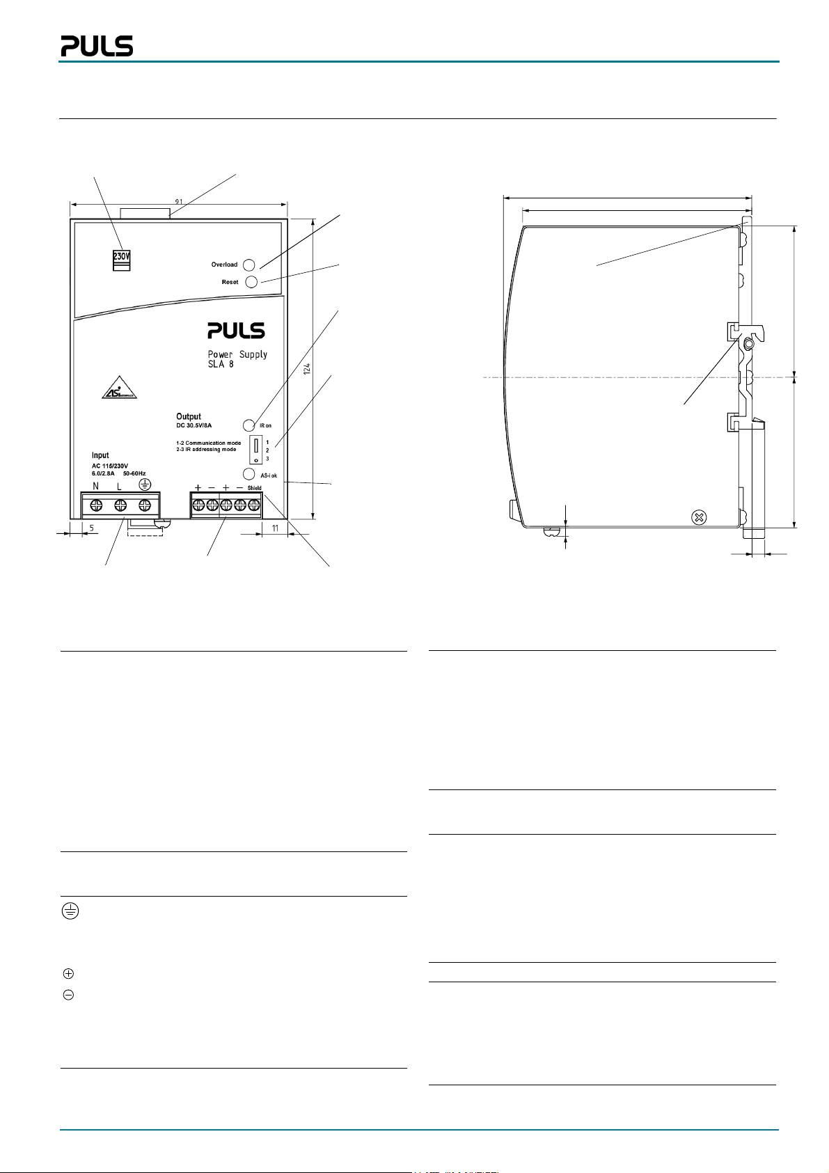
Start behaviour
U
Out
30.6V
115V
68 Vac
switch pos.
82 Vac
switch pos.
135 Vac
Efficiency / Power dissipation
0,94
0,92
0,9
0,88
0,86
Efficiency [%]
0,84
0,82
0,8
230 V
position
Efficiency
Power l oss
0 0,8 1,6 2,4 3,2 4 4,8 5,6 6,4 7,2 8
Output current Iout [A]
230V
162 Vac
U
In
22
20
18
16
14
12
10
8
6
Power loss Ploss [W]
4
2
0
FUSE Mode / Signals and LED
I
out
I
rated
LED
Overload
LED
Green
Reset
(Button)
2...5s
Overload
ca. 4Hz
time
time
time
time
Overload response until FUSE Mode
is activated
35
30
25
20
15
10
Output voltage [Vout]
5
0
02468101214
Output current [Iout]
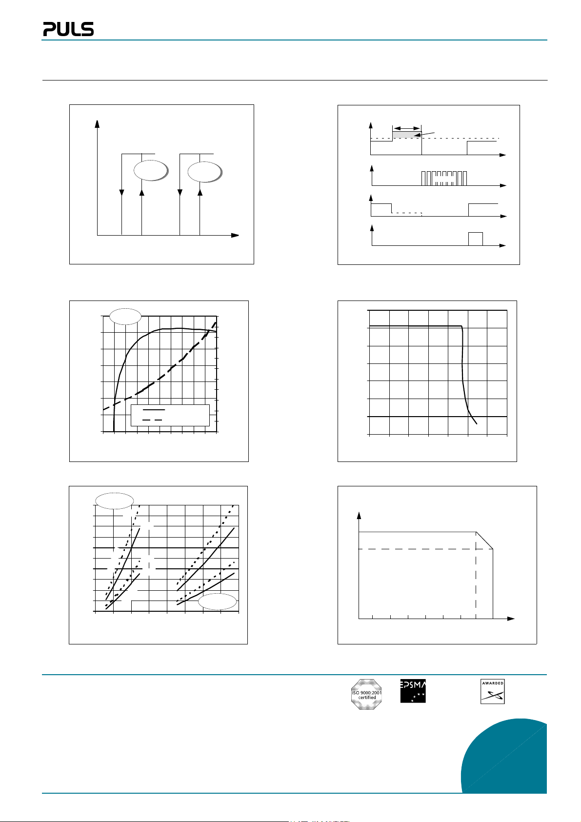
Hold-up time
115V
switch pos.
100
90
80
70
60
50
40
30
Hold-up time [ms]
20
10
0
70 95 120 145 170 195 220 245 270
typ.
d
a
o
l
typ.
%
0
5
d
a
o
l
l
l
u
f
Input voltage V ACin [V]
min.
min.
230V
switch pos.
Derating
I
(P
max
max
8A
6A
-10°C
0°C
)
T
amb
10°C
20°C
30°C
40°C
50°C
60°C
70°C
Unless otherwise stated, specifications are valid for AC 230V input voltage, +25°C ambient temperature, and 5 min. run-in time. They are subject to change without prior notice.
Your partner in power supply:
European
Power Supply
Manufacturers
Association
Bayerns Best 50
Czech 100 Best
Europe’s 500
PULS GmbH
Arabellastraße 15
D-81925 München
Tel.: +49 89 9278-0
Fax: +49 89 9278-199
www.puls-power.com
4/4 sla8e100 / 040225
 Loading...