

Page 1
Q-Series
QS20.241, QS20.241-C1
24V, 20A, SINGLE PHASE INPUT
5. AC-INPUT
AC input
AC input range
min. 60-85Vac full power for 200ms, no damage between 0 and 85Vac
Input frequency
Turn-on voltage typ. 77Vac steady-state value, see Fig. 5-1
Shut-down voltage typ. 73Vac steady-state value, see Fig. 5-1
AC 100V AC 120V AC 230V
Input current typ. 5.47A 4.56A 2.48A at 24V, 20A, see Fig. 5-3
Power factor *) typ. 0.96 0.95 0.90 at 24V, 20A, see Fig. 5-4
Crest factor **) typ. 1.6 1.7 2.05 at 24V, 20A
Start-up delay typ. 640ms 610ms 660ms see Fig. 5-2
Rise time typ. 80ms 80ms 80ms 0mF, 24V, 20A, see Fig. 5-2
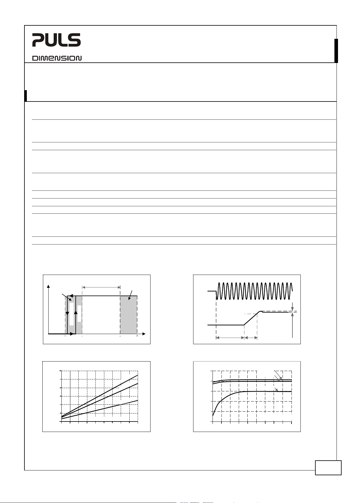
Turn-on overshoot
*) The power factor is the ratio of the true (or real) power to the apparent power in an AC circuit.
**) The crest factor is the mathematical ratio of the peak value to RMS value of the input current waveform.
Fig. 5-1 Input voltage range Fig. 5-2 Turn-on behavior, definitions
P
OUT
full
power
for
200ms
Shut-down
60V 300Vac
input range
Turn-on
85V
Rated
Fig. 5-3 Input current vs. output load at 24V Fig. 5-4 Power factor vs. output load at 24V
Input Current, typ.
6A
5
4
3
2
1
0
2 4 6 8 10 12 14 16 18
Output Current
nom. AC 100-240V wide-range input, TN-, TT-, IT-Mains, see Fig. 5-1
min. 85-276Vac continuous operation
min. 276-300Vac < 500ms
nom. 50 – 60Hz ±6%
typ. 53Vac dynamical value
typ. 85ms 85ms 85ms 20mF, 24V, 20A, see Fig. 5-2
max. 50mV 50mV 50mV see Fig. 5-2
Input
Voltage
Output
Voltage
Power Factor, typ.
1.0
0.95
0.9
0.85
0.8
0.75
2 4 6 8 10 12 14 16 18 20A
- 5%
Start-up
delay
Rise
Time
100Vac
120Vac
230Vac
Output Current
Overshoot
276V
1
2
max.
500ms
0
0
1
0
2
30
V
IN
c
a
V
c
a
V
ac
V
20A
Jan. 2008 / Rev. 1.3 DS-QS20.241-EN
All parameters are specified at 24V, 20A, 230Vac, 25°C ambient and after a 5 minutes run-in time unless otherwise noted.
www.pulspower.com Phone +49 89 9278 0 Germany
3/25
Page 2
Q-Series
QS20.241, QS20.241-C1
24V, 20A, SINGLE PHASE INPUT
6. INPUT INRUSH CURRENT
An active inrush limitation circuitry limits the input inrush current after turn-on of the input voltage.
The charging current into EMI suppression capacitors is disregarded in the first millisecond after switch-on (EN 61204).
Inrush current max. 13A
typ. 11A
Inrush energy
Inrush delay
max. 5A2s 5A2s 5A2s -25°C to +70°C, mains interruptions > 750ms
typ. 400ms 400ms 650ms
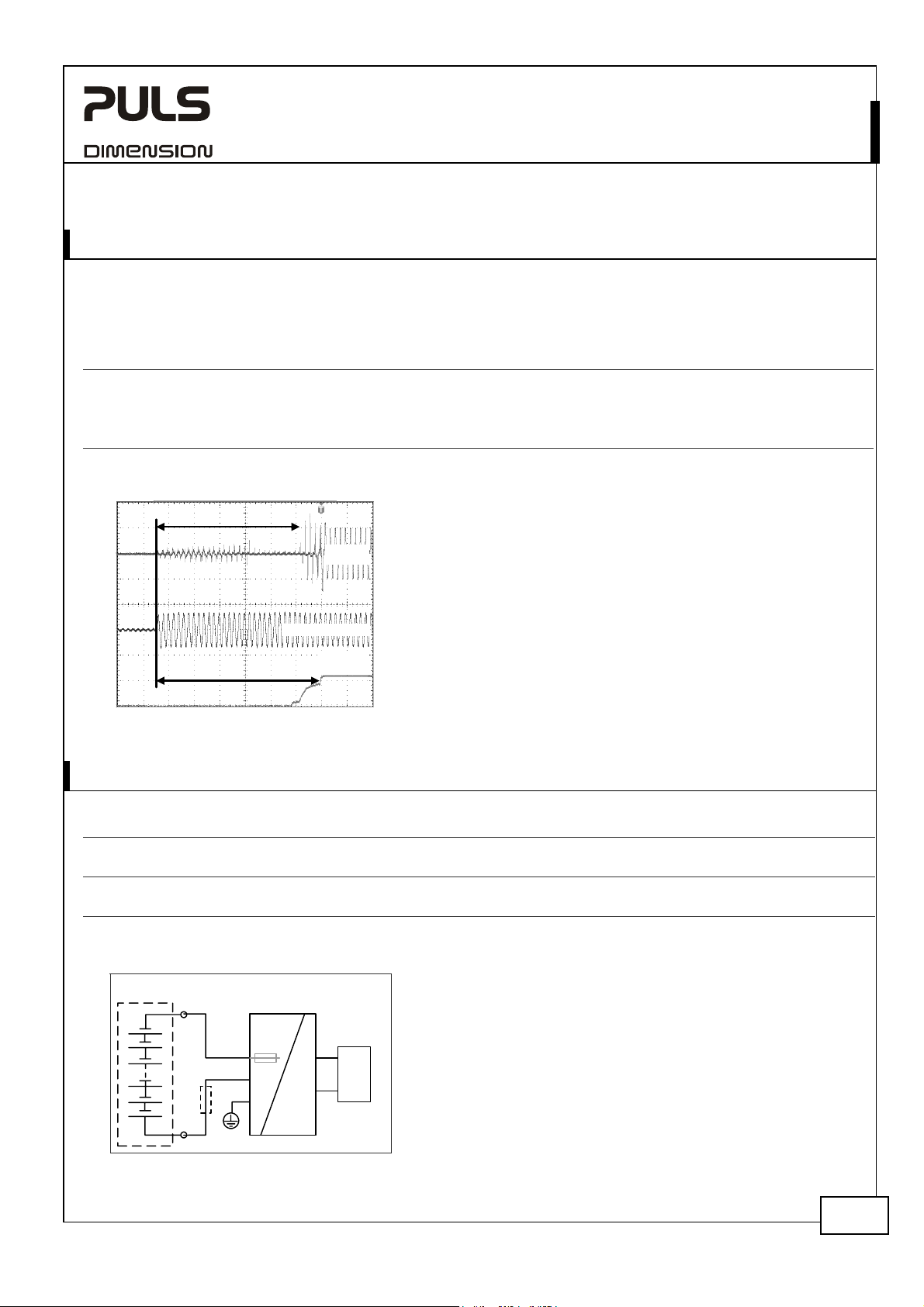
Fig. 6-1 Input inrush current, typical behavior
A
B
AC 100V AC 120V AC 230V
peak
peak
Input
Current
13A
9A
13A
peak
7A
peak
Input Voltage
Output
Voltage
-25°C to +70°C, mains interruptions > 750ms
peak
-25°C to +70°C, mains interruptions > 750ms
peak
A: Inrush delay
B: Start-up delay
Input: 230Vac
Output: 24V, 20A
Ambient: 25°C
Upper curve: Input current 5A / DIV
Medium curve: Input voltage 500V / DIV
Lower curve: Output voltage 20V / DIV
Time basis: 100ms / DIV
7. DC-INPUT
DC input nom. DC 110-300V
DC input range min. 88-375Vdc continuous operation
DC input current typ. 4.7A / 1.7A 110Vdc / 300Vdc, 24V, 20A
Turn-on voltage typ. 74Vdc steady state value
Shut-down voltage typ. 69Vdc steady state value
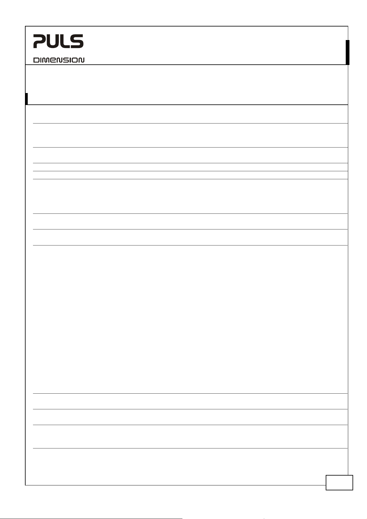
Fig. 7-1 Wiring for DC Input
Battery
Power Supply
+
Fuse
-
PE
L
N
AC
internal
fused
DC
+
Load
-
Instructions for DC use:
a) Use a battery or similar DC source.
b) Connect +pole to L and –pole to N.
c) Connect the PE terminal to an earth wire or
to the machine ground.
In case the –pole of the battery is not connected
to earth, use an appropriate fuse to protect the N
terminal.
Jan. 2008 / Rev. 1.3 DS-QS20.241-EN
All parameters are specified at 24V, 20A, 230Vac, 25°C ambient and after a 5 minutes run-in time unless otherwise noted.
www.pulspower.com Phone +49 89 9278 0 Germany
4/25
Page 3
Q-Series
QS20.241, QS20.241-C1
24V, 20A, SINGLE PHASE INPUT
8. OUTPUT
Output voltage
Adjustment range
max. 30V at clockwise end position of potentiometer
Factory setting
Line regulation
Load regulation max. 100mV static value, 0A Æ 20A Æ 0A
Ripple and noise voltage
Output capacitance typ. 8 500µF
Continuous power capability
Output current
Output power
nom. 480W 28V, continuous
Short-circuit current
max. 40A
BonusPower®, short term power capability (up to typ. 4s)
The power supply is designed to support loads with a higher short-term power requirement without damage or
shutdown. The short-term duration is hardware controlled by an output power manager. This BonusPower® is
repeatedly available. Detailed information can be found in chapter 27.1. If the power supply is loaded longer with
the BonusPower® than shown in the Bonus-time diagram (see Fig. 8-2), the max. output power is automatically
reduced to 480W.
If the power requirement is continuously above 480W and the voltage falls below approx. 20V (due to the current
regulating mode at overload), the unit shuts-off and makes periodical restart attempts. This behavior is called hiccup
mode which is described below. If the voltage is above 20V, the unit continuously delivers current.
Hiccup Mode:
Up to 4s of overloading, the power supply delivers continuous output current. After this, the output power is reduced
to nearly zero for approx. 17s before a new start attempt is automatically performed. If the overload has been
cleared, the device will operate normally. If the overload still exists, the output current will be delivered for 2 to 4s
(depending on the overload) again followed by a17 s rest time. This cycle is repeated as long as the overload exists.
See Fig. 8-3. During the off-period a small rest voltage and rest current is present on the output.
Output current
Output power
nom. 720W 28V, short term
Short-circuit current
max. 40A load impedance 50mOhm, up to 4s, see Fig. 8-1
Bonus time
min 3.5s see Fig. 8-2
nom. 24V
min. 24-28V guaranteed, multi turn potentiometer
max. 10mV 60 to 300Vac
max. 100mVpp 20Hz to 20MHz, 50Ohm
nom. 20A at 24V, see Fig. 8-1
nom. 17A
nom. 480W 24V, continuous
min. 30A
nom. 30A at 24V, see Fig. 8-1
nom. 26A
nom. 720W 24V, short term
min. 30A load impedance 50mOhm, up to 4s, see Fig. 8-1
typ. 4s at 24V, 30A, duration until the output voltage dips,
max. 4.5s
24.1V
±0.2%, at full load, cold unit
at 28V, see Fig. 8-1
load impedance 50mOhm, up to 4s before hiccup mode
starts, see Fig. 8-1 and Fig. 8-3
at 28V, see Fig. 8-1
Jan. 2008 / Rev. 1.3 DS-QS20.241-EN
All parameters are specified at 24V, 20A, 230Vac, 25°C ambient and after a 5 minutes run-in time unless otherwise noted.
www.pulspower.com Phone +49 89 9278 0 Germany
5/25
Page 4

Q-Series
QS20.241, QS20.241-C1
24V, 20A, SINGLE PHASE INPUT
Fig. 8-1 Output voltage vs. output current, typ. Fig. 8-2 Bonus time vs. output power
Output Voltage
28V
24
20
16
12
8
4
0
0 5 10 20 25
Short term <5s then auto
A
switching to curve +
B
Continuously available
Below 20Vdc hiccup mode
C
B
C
B
A
C
Output
Current
40A15 30
35
Bonus Time
10s
9
8
7
6
5
m
a
4
3
2
1
0
m
i
n
Output Power
110 120 130 140 150
x
Fig. 8-3 Short-circuit on output, hiccup mode, typical behavior
Output
Current
f
a
r
t
o
t
S
s
h
t
i
u
c
r
c
i
o
r
t
s
h
35A
f
o
d
E
n
t
i
u
c
r
c
i
o
r
t
typ
160%
0
17s
17s17s 2s 2s2s
t
The Bonus Power
®
is available as soon as power comes on and immediately after the end of an output short circuit or
output overload.
Fig. 8-4 BonusPower® after input turn-on
Input
Voltage
Output
Voltage
150%
Output
100%
Power
Bonus
Power
Fig. 8-5 BonusPower® after output short
Short of
Output
Output
Voltage
Output
Power
150%
100%
Bonus
Power
Peak current capability (up to several ms)
The power supply can deliver a peak current which is higher than the specified short term current. This helps to start
current demanding loads or to safely operate subsequent circuit breakers.
The extra current is supplied by the output capacitors inside the power supply. During this event, the capacitors will
be discharged and causes a voltage dip on the output. Detailed curves can be found in chapter 27.2.
Peak current voltage dips typ. from 24V to 19V at 40A for 20ms
typ. from 24V to 18V
typ. from 24V to 17.5V
at 80A for 2ms
at 80A for 5ms
Jan. 2008 / Rev. 1.3 DS-QS20.241-EN
All parameters are specified at 24V, 20A, 230Vac, 25°C ambient and after a 5 minutes run-in time unless otherwise noted.
www.pulspower.com Phone +49 89 9278 0 Germany
6/25
Page 5

Q-Series
QS20.241, QS20.241-C1
24V, 20A, SINGLE PHASE INPUT
9. HOLD-UP TIME
AC 100V AC 120V AC 230V
Hold-up Time typ. 32ms 32ms 51ms 20A, 24V, see
typ. 64ms 64ms 99ms 10A, 24V, see Fig. 9-1
Fig. 9-1 Hold-up time vs. input voltage Fig. 9-2 Shut-down behavior, definitions
90
80
70
60
Hold-up
Time
4
2
2
100ms
50
40
30
20
10
Input Voltage
85 120 155 190 230Vac
V
4
2
4
2
.
p
y
t
,
A
0
1
,
,
V
V
4
V
.
n
i
m
A,
0
1
.
p
y
t
,
A
0
2
,
.
n
i
m
,
A
0
2
,
Input
Voltage
Output
Voltage
Hold-up Time
Fig. 9-1
Zero Transition
- 5%
Jan. 2008 / Rev. 1.3 DS-QS20.241-EN
All parameters are specified at 24V, 20A, 230Vac, 25°C ambient and after a 5 minutes run-in time unless otherwise noted.
www.pulspower.com Phone +49 89 9278 0 Germany
7/25
Page 6

Q-Series
QS20.241, QS20.241-C1
24V, 20A, SINGLE PHASE INPUT
10. DC-OK RELAY CONTACT
This feature monitors the output voltage, which is produced by the power supply itself. It is independent of a backfed voltage from a unit which is connected in parallel to the power supply output.
Contact closes As soon as the output voltage reaches the adjusted output voltage.
Contact opens As soon as the output voltage dips more than 10% below the adjusted output voltage.
Contact re-closes As soon as the output voltage exceeds 90% of the adjusted voltage.
Contact ratings max 60Vdc 0.3A, 30Vdc 1A, 30Vac 0.5A resistive load
min 1mA at 5Vdc min. permissible load
Isolation voltage See dielectric strength table in section 20
Fig. 10-1 DC-ok relay contact behavior
V
=
V
OUT
ADJ
90%
V
ADJ
open
<
1ms
Restrictions apply when using the DC-OK Contact in a Haz-Loc environment:
The DC-OK contact is intended to be used for a separately investigated nonincendive field wiring and/or field wiring
apparatus. The apparatus may be located in a Class I, Division 2 (Group A, B, C or D) hazardous (classified) location.
Non associated nonincendive field wiring apparatus shall not be connected in parallel unless this is permitted by the
associated nonincendive field wiring apparatus approval.
Selected barriers must have entity parameters such that Voc < V max, Isc < I max, Ca > Ci + Ccable, La > Li + Lcable.
For Ccable and Lcable, if the capacitance per foot or the inductance per foot is not known, then the following values
shall be used: Ccable = 60pF/foot and Lcable = 0.2uH/foot.
Fig. 10-2 DC-ok control drawing for use in Haz-
+
-
Output
Power
Supply
Short dips will be extended to a signal length of 250ms. Dips shorter than 1ms will be ignored.
Note:
The DC-ok feature requires that the output voltage
10%
reaches the nominal (=adjusted) level after turn-on in
order to function according to specification. If this level
cannot be achieved, the overload LED will be on and
>
1ms
250ms
the DC-ok contact will be open. The overload signal will
only shut off as soon as the adjusted voltage is reached.
This is an important condition to consider particularly, if
the load is a battery, the power supply is used in
openclosed closed
Loc environments
Hazardous
Location
Non Hazardous
Location
parallel or the power supply is used for N+1 redundant
systems.
Contact current: I max = 50mA,
Contact voltage: V max. = 35V (DC or AC)
Max. associated circuit capacitance Ca = 100nF
Max. associated circuit inductance La = 20mH
Isc
DCok
13
Voc
Apparatus
No polarity requirement
Input
LNPE
14
Jan. 2008 / Rev. 1.3 DS-QS20.241-EN
All parameters are specified at 24V, 20A, 230Vac, 25°C ambient and after a 5 minutes run-in time unless otherwise noted.
www.pulspower.com Phone +49 89 9278 0 Germany
8/25
Page 7

Q-Series
QS20.241, QS20.241-C1
24V, 20A, SINGLE PHASE INPUT
11. EFFICIENCY AND POWER LOSSES
AC 100V AC 120V AC 230V
Efficiency typ. 91.6% 92.4% 93.9% 20A, 24V
Power losses typ. 44.0W 39.6W 31.4W 20A, 24V
typ. 9.0W 9.2W 10.0W 0A
Fig. 11-1 Efficiency vs. output current at 24V Fig. 11-2 Losses vs. output current at 24V
Efficiency
94%
230Vac
1
93
92
91
90
89
88
87
86
4 6 8 101214161820A
2
1
00
Output Current
0
V
a
c
V
a
c
Power Losses
45W
40
35
30
25
20
15
10
5
02468101214 20A
Fig. 11-3 Efficiency vs. input voltage, 24V, 20A Fig. 11-4 Losses vs. input voltage, 24V, 20A
Efficiency
94%
93
92
91
90
89
88
85 120 155 190 225 260
Input Voltage
Vac
Power Losses
50W
45
40
35
30
25
20
85 120 155 190 225 260
100Vac
120Vac
230Vac
Output Current
16 18
Input Voltage
Vac
Jan. 2008 / Rev. 1.3 DS-QS20.241-EN
All parameters are specified at 24V, 20A, 230Vac, 25°C ambient and after a 5 minutes run-in time unless otherwise noted.
www.pulspower.com Phone +49 89 9278 0 Germany
9/25
 Loading...