

Page 1
Q-Series
QS20.241, QS20.241-C1
24V, 20A, SINGLE PHASE INPUT
27. APPLICATION NOTES
27.1. REPETITIVE PULSE LOADING
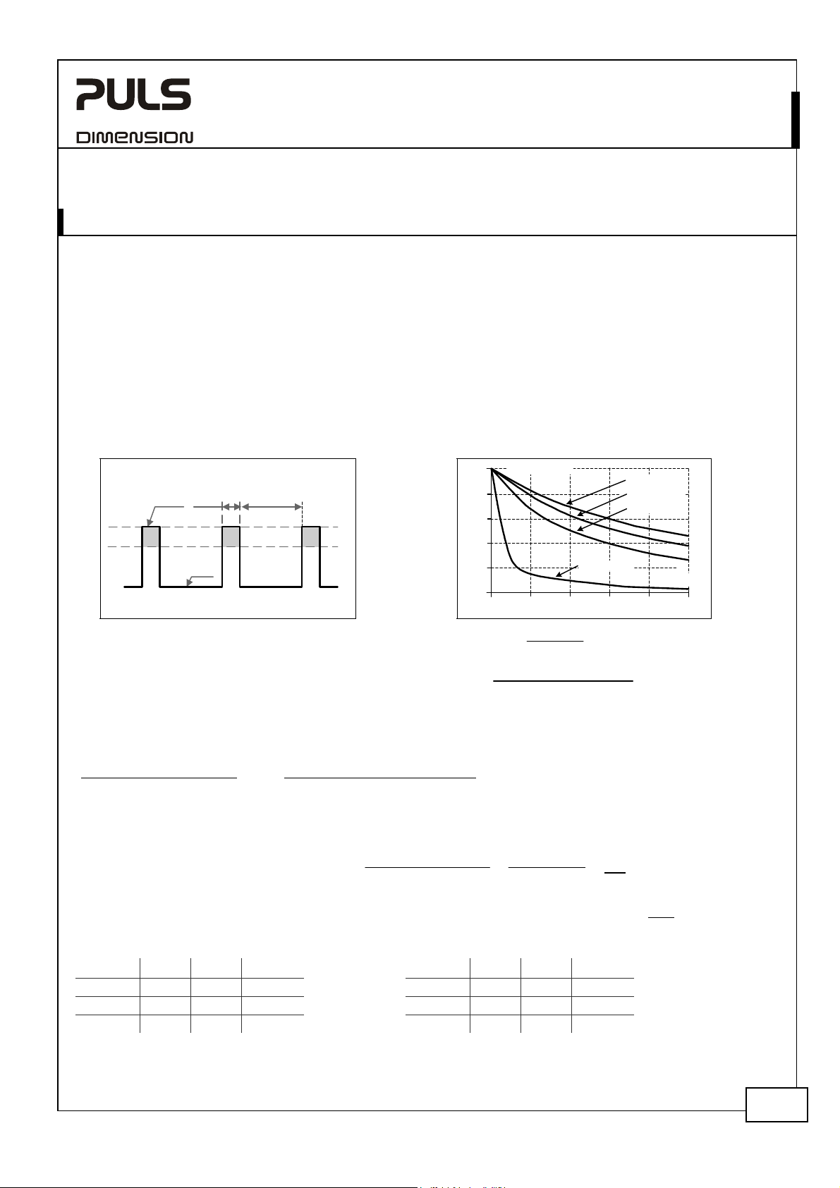
Typically, a load current is not constant. It varies over time. For pulse load compatibility, following rules must be met:
a) The pulse power demand must be below 150% of the nominal power.
b) The duration of the pulse power must be shorter than the allowed Bonus Time. (see output section)
c) The average (R.M.S.) output current must be below the specified continuous output current.
If the R.M.S. current is higher, the unit will respond with a thermal shut-down after a while. Use the max. duty
cycle curve (Fig. 27-2) to check if the average output current is below the nominal current.
d) For altitudes higher than 2000m reduce the pulse loading (30W/1000m) or the ambient temperature (5°C/1000m)
Fig. 27-1 Repetitive pulse loads, definitions Fig. 27-2 Max. Duty Cycle Curve
0
utyCycle
PEAK
)
=
T
0
DutyCycle
=
P0
1
110 120 130 140
T
peak
=
T
peak + T0
T
peak -
(D
utyCycle
x T
peak
D
utyCycle
= 150%
0
1s - (0.37 x 1s)
0.37
PEAK
=1.7s
T0
P
=
1
%
0
0
P
=
0
5
%
0
P
=
%
5
7
0
0
0
%
P
PEAK
150%100
)
= 50% curve
0
:
1.0
P
max.
150%
100%
PEAKTPEAK
P
0
T
0
0.8
0.6
0.4
0.2
P
Base load (W)
0
P
Pulse load (above 100%)
PEAK
Duration between pulses (s)
T
0
T
Pulse duration (s)
PEAK
D
T0 =
Utilizing the Max. Duty Cycle Curve:
Example to determine the repetition rate of pulses without dipping of the output voltage:
Parameters of application:
Pulse length is T
PEAK = 1s
Steady state load P
(= 50% of I
RATED
0=120W
)
Peak load P
(= 150% of I
PEAK = 360W
)
RATED
Determining the repetition rate:
1) make a vertical line at P
2) make a horizontal line where the vertical line crosses the P
3) Read the Max. Duty Cycle from the Duty Cycle-axis (= 0.37)
4) Calculate the min. pause (base load) length T
T
peak -
(D
utyCycle
x T
T0 =
D
utyCycle
peak
5) Pulse length = 1s, min. pause length = 1.7s
6) Max. repetition rate = pulse length +pause length = 2.7s
More examples for pulse load compatibility:
P
P
PEAK
T
0
PEAK
T0
P
P
PEAK
720W 480W 1s >25s 720W 240W 0.1s >0.16s
720W 0W 1s >1.3s 720W 240W 1s >1.6s
600W 240W 1s > 0.75s 720W 240W 3s >4.9s
Jan. 2008 / Rev. 1.3 DS-QS20.241-EN
All parameters are specified at 24V, 20A, 230Vac, 25°C ambient and after a 5 minutes run-in time unless otherwise noted.
www.pulspower.com Phone +49 89 9278 0 Germany
19/25
Page 2
Q-Series
QS20.241, QS20.241-C1
24V, 20A, SINGLE PHASE INPUT
27.2. PEAK CURRENT CAPABILITY
Solenoids, contactors and pneumatic modules often have a steady state coil and a pick-up coil. The inrush current
demand of the pick-up coil is several times higher than the steady state current and usually exceeds the nominal
output current (including the Bonus Power®) The same situation applies, when starting a capacitive load.
Branch circuits are often protected with circuit breakers or fuses. In case of a short or an overload in the branch
circuit, the fuse needs a certain amount of over-current to trip or to blow. The peak current capability ensures the
safe operation of subsequent circuit breakers.
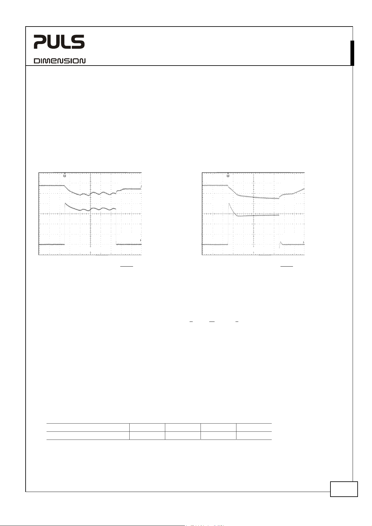
Assuming the input voltage is turned on before such an event, the built-in large sized output capacitors inside the
power supply can deliver extra current. Discharging this capacitor causes a voltage dip on the output. The following
two examples show typical voltage dips:
Fig. 27-3 Peak load 40A for 50ms, typ. Fig. 27-4 Peak load 80A for 5ms, typ.
24V
40A
Output
Voltage
19.0V
24V
80A 17.5V
Output
Voltage
0A
10ms/DIV
Peak load 40A (resistive) for 50ms
Output voltage dips from 24V to 19.0V.
Output
Current
0A
Peak load 80A (nearly resistive) for 5ms
Output voltage dips from 24V to 17.5V.
1ms/DIV
Output
Current
Please note: The DC-OK relay triggers when the voltage dips more than 10% for longer than 1ms.
27.3. BACK-FEEDING LOADS
Loads such as decelerating motors and inductors can feed voltage back to the power supply. This feature is also called
return voltage immunity or resistance against Back- E.M.F. (E
lectro Magnetic Force).
This power supply is resistant and does not show malfunctioning when a load feeds back voltage to the power
supply. It does not matter, whether the power supply is on or off.
The maximum allowed feed back voltage is 34Vdc. The absorbing energy can be calculated according to the built-in
large sized output capacitor which is specified in chapter 8. If the feed back voltage gets higher than 34Vdc, the
power supply responds with a shut-down and a subsequent start-up attempt.
27.4. CHARGING OF BATTERIES
The power supply can be used for float-charging of lead-acid or maintenance free 24V VRLA batteries.
Instructions for charging batteries:
a) Set the output voltage, at disconnected load, very precisely to the end-of-charge voltage according to the
expected battery temperature.
End-of-charge voltage 27.8V 27.5V 27.15V 26.8V
Battery temperature 10°C 20°C 30°C 40°C
b) Use a 25A circuit breaker (or blocking diode ) between the power supply and the battery.
c) Ensure that the output current of the power supply is below the allowed charging current of the battery.
d) Use only matched batteries when putting 12V types in series.
e) The return current to the power supply is typ. 9mA at 25Vdc when the power supply is switched off.
Jan. 2008 / Rev. 1.3 DS-QS20.241-EN
All parameters are specified at 24V, 20A, 230Vac, 25°C ambient and after a 5 minutes run-in time unless otherwise noted.
www.pulspower.com Phone +49 89 9278 0 Germany
20/25
Page 3
Q-Series
QS20.241, QS20.241-C1
24V, 20A, SINGLE PHASE INPUT
27.5. OUTPUT CIRCUIT BREAKERS
Standard miniature circuit breakers (MCBs) can be used for branch protection. Ensure that the MCB is rated for DC
voltage, too. The following tests show which circuit breakers the power supply typically trips.
Circuit breakers have huge tolerances in their tripping behavior. Therefore, these typical tests can only be used as a
recommendation or for comparing two different power supplies. Furthermore, the loop impedance has a major
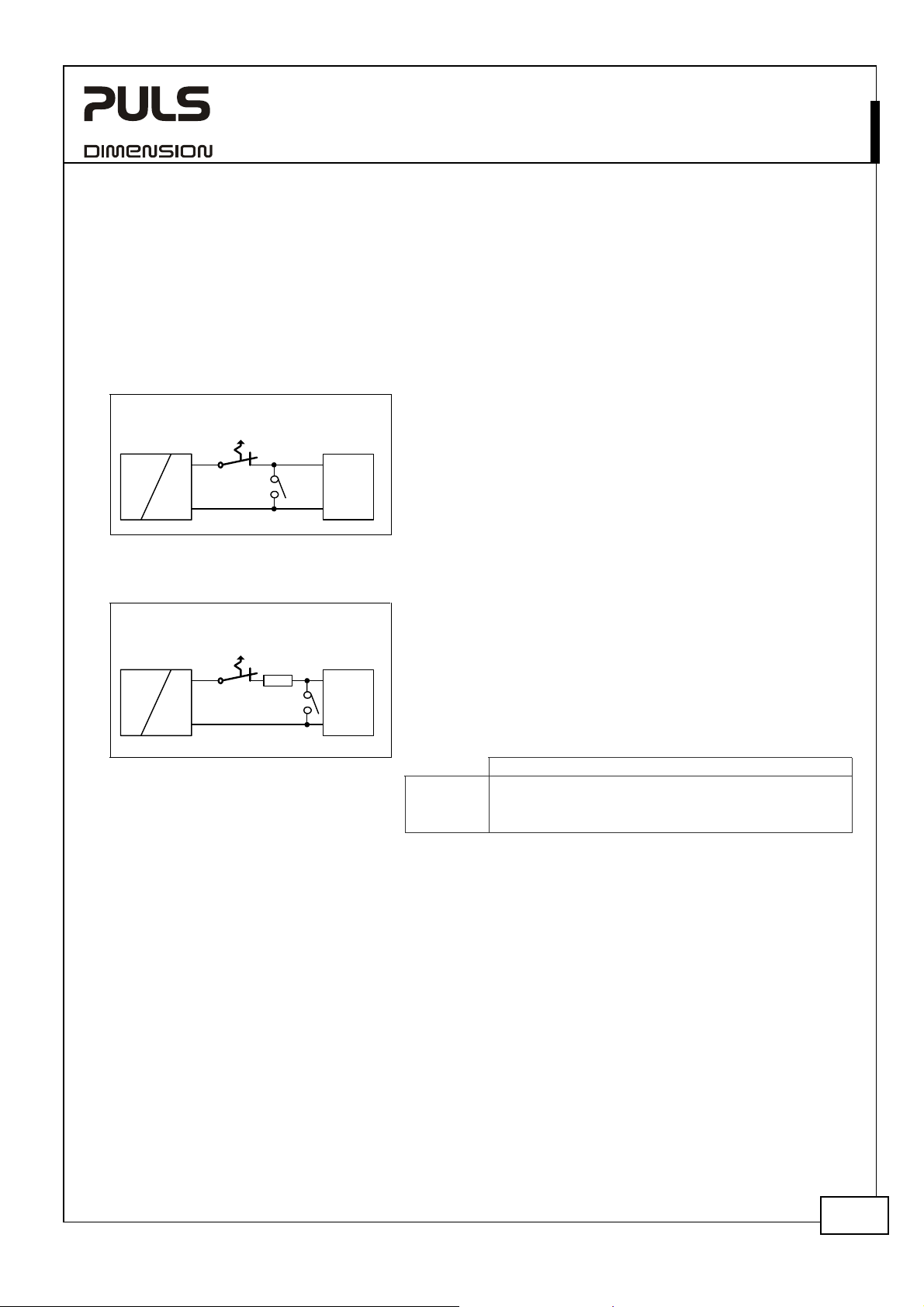
influence on whether a breaker trips or not. Two tests were performed, representing typical situations:
Test 1: Short circuit with S1 on the power supply end of the cable (loop impedance approx. 20mOhm)
Fig. 27-5 Branch protectors, test circuit 1
Circuit
Power
Supply
AC
DC
Breaker
I
+
S1
-
+
Load
-
Test 2: Short circuit with S1 on the load end (additional impedance included; represents longer load wire length).
Fig. 27-6 Branch protectors, test circuit 2
Circuit
Power
Supply
AC
DC
Breaker
I
+
-
R
+
S1 Load
-
*) A list of the circuit breakers under test is available on request.
Example:
Which wire gauge must be used to trip a C-Characteristic circuit breaker with a rating of 8A? The load wire length is
19m.
Answer: A 8A C-Characteristic circuit breaker requires a loop impedance of less than 150mOhm (test results). The wire
length table shows that up to 20.9m wire with a cross section of 2.5mm
than 2.5mm
2
shall be used.
82mOhm
120mOhm
150mOhm
Parameters:
Input voltage: 230Vac, load current: 0A
Tripping time shorter than 5s.
The following circuit breaker tripped during the test:
A- or Z- Characteristic:: equal or smaller 25A *)
B- Characteristic: equal or smaller 20A *)
C- Characteristic: equal or smaller 13A *)
Parameters:
Input voltage: 230Vac, load current: 0A
Tripping time shorter than 5s.
The following circuit breaker tripped during the test:
A- or Z- Characteristic:: ≤ 20A and R< 82mOhm *)
B- Characteristic: ≤ 13A and R< 120mOhm *)
C- Characteristic: ≤ 8A and R< 150mOhm *)
What does this resistance mean in wire length?
2
0.5mm
0.7mm2 1.0mm2 1.5mm2 2.5mm2 4.0mm2
2.3m 3.2m 4.6m 6.9m 11.4m 18.3m
3.3m 4.7m 6.7m 10.0m 16.7m 26.7m
4.2m 5.9m 8.4m 12.5m 20.9m 33.4m
2
are below 150mOhm. A wire not smaller
Jan. 2008 / Rev. 1.3 DS-QS20.241-EN
All parameters are specified at 24V, 20A, 230Vac, 25°C ambient and after a 5 minutes run-in time unless otherwise noted.
www.pulspower.com Phone +49 89 9278 0 Germany
21/25
Page 4

Q-Series
QS20.241, QS20.241-C1
24V, 20A, SINGLE PHASE INPUT
27.6. EXTERNAL INPUT PROTECTION
The unit is tested and approved for branch circuits up to 20A. External protection is only required, if the supplying
branch has an ampacity greater than this. In some countries local regulations might apply. Check also local codes and
local requirements.
If an external fuse is necessary or utilized, a minimum value is required to avoid undesired tripping of the fuse.
B-Characteristic C-Characteristic
Ampacity max.
min.
20A 20A
10A 10A
27.7. PARALLEL USE TO INCREASE OUTPUT POWER
Power supplies can be paralleled to increase the output power.
Fig. 27-7 Schematic for parallel operation
Unit A
AC
Unit B
AC
DC
DC
+
-
+
-
+
Load
-
Instructions for parallel use:
a) Use only power supplies from the same series (Q-Series).
b) Adjust the output voltages of all power supplies to
approximately the same value (±500mV).
Otherwise, the DC-ok signal might not work properly.
c) A fuse (or diode) on the output is only required if more than
three units are connected in parallel.
d) Do not continuously load the terminals with more than 25A.
Follow wiring instructions according to chapter 27.9
e) Keep an installation clearance of 15mm (left/right) between
two power supplies and avoid installing the power supplies
on top of each other.
27.8. PARALLEL USE FOR REDUNDANCY
Power supplies can be paralleled for redundancy to gain a higher system availability. Redundant systems require a
certain amount of extra power to support the load in case one power supply unit fails. The simplest way is to put two
Q-Series power supplies in parallel. This is called a 1+1 redundancy. In case one power supply unit fails, the other one
is automatically able to support the load current without any interruption. Redundant systems for a higher power
demand are usually built in a N+1 method. E.g. Five power supplies, each rated for 10A are paralleled to build a 40A
redundant system.
Please note: This simple way to build a redundant system does not cover failures such as an internal short circuit in
the secondary side of the power supply. In such a - virtually nearly impossible - case, the defect unit becomes a load
for the other power supplies and the output voltage can not be maintained any more. This can only be avoided by
utilizing decoupling diodes which are included in the decoupling module YR2.DIODE. (One Diode module per power
supply)
Recommendations for building redundant power systems:
a) Use separate input fuses for each power supply.
b) Monitor the individual power supply units. A DC-ok LED and a DC-ok contact is already included in the units.
This feature reports a faulty unit.
c) When possible, connect each power supply to different phases or circuits.
d) It is desirable to set the output voltages of all power supplies to the same value to avoid a false DC-ok signal.
Jan. 2008 / Rev. 1.3 DS-QS20.241-EN
All parameters are specified at 24V, 20A, 230Vac, 25°C ambient and after a 5 minutes run-in time unless otherwise noted.
www.pulspower.com Phone +49 89 9278 0 Germany
22/25
Page 5

Q-Series
QS20.241, QS20.241-C1
24V, 20A, SINGLE PHASE INPUT
27.9. DAISY-CHAINING OF OUTPUTS
Daisy chaining (jumping from one power supply output to the next) is allowed as long as the max. current through
one terminal pin does not continuously exceed 20A. If the current is higher, use a separate distribution terminal.
Fig. 27-8 Daisy chaining of outputs
max 20A!
+ +
- -
Power
Supply
Input
+ +
- -
Power
Supply
Input
+
Load
-
Fig. 27-9 Using distribution terminals
+ +
- -
Power
Supply
Input
+ +
- -
Power
Supply
Input
Distribution
Terminals
+
Load
-
27.10. SERIES OPERATION
The power supply can be put in series to increase the output voltage.
Fig. 27-10 Schematic for series operation
Instructions for use in series:
a) It is possible to connect as many units in series as needed,
providing the sum of the output voltage does not exceed
Unit A
AC
Unit B
AC
DC
DC
+
+
Load
+
-
-
Earth
150Vdc.
b) Voltages with a potential above 60Vdc are not SELV any
more and can be dangerous. Such voltages must be installed
with a protection against touching.
c) For serial operation use power supplies of the same type.
d) Earthing of the output is required when the sum of the
output voltage is above 60Vdc.
e) Keep an installation clearance of 15mm (left/right) between
two power supplies and avoid installing the power supplies
on top of each other.
Avoid return voltage (e.g. from a decelerating motor or
Note:
battery) which is applied to the output terminals.
27.11. INDUCTIVE AND CAPACITIVE LOADS
The unit is designed to supply any kind of load, including unlimited capacitive and inductive loads.
Jan. 2008 / Rev. 1.3 DS-QS20.241-EN
All parameters are specified at 24V, 20A, 230Vac, 25°C ambient and after a 5 minutes run-in time unless otherwise noted.
www.pulspower.com Phone +49 89 9278 0 Germany
23/25
Page 6

Q-Series
27.12. OPERATION ON TWO PHASES
Fig. 27-11 Schematic for two phase operation
L1
L3
L2
max.
+15%
240V
Power Supply
Fuse
PE
L
N
AC
internal
fused
DC
27.13. USE IN A TIGHTLY SEALED ENCLOSURE
QS20.241, QS20.241-C1
24V, 20A, SINGLE PHASE INPUT
Instructions for two phase operation:
a) A phase to phase connection is allowed as long as the
supplying voltage is below 240V
b) Use a fuse or a circuit breaker to protect the N input. The
N input is internally not protected and is in this case
connected to a hot wire.
Appropriate fuses or circuit breakers are specified in section 27.6
“External Input Protection”.
+15%
.
When the power supply is installed in a tightly sealed enclosure, the temperature inside the enclosure will be higher
than outside. The inside temperature defines the ambient temperature for the power supply.
Results from such an installation:
Power supply is placed in the middle of the box, no other heat producer inside the box
Enclosure: Rittal Type IP66 Box PK 9522 100, plastic, 254x180x165mm
Load: 24V, 16A; (=80%) load is placed outside the box
Input: 230Vac
Temperature inside enclosure: 49.2°C (in the middle of the right side of the power supply with a distance of 2cm)
Temperature outside enclosure: 24.4°C
Temperature rise: 24.8K
Jan. 2008 / Rev. 1.3 DS-QS20.241-EN
All parameters are specified at 24V, 20A, 230Vac, 25°C ambient and after a 5 minutes run-in time unless otherwise noted.
www.pulspower.com Phone +49 89 9278 0 Germany
24/25
Page 7

C
C
C
C
C
Q-Series
QS20.241, QS20.241-C1
24V, 20A, SINGLE PHASE INPUT
27.14. MOUNTING ORIENTATIONS
Mounting orientations other than input terminals on the bottom and output on the top require a reduction in
continuous output power or a limitation in the max. allowed ambient temperature. The amount of reduction
influences the lifetime expectancy of the power supply. Therefore, two different derating curves for continuous
operation can be found below:
Curve A1 Recommended output current.
Curve A2 Max allowed output current (results approx. in half the lifetime expectancy of A1).
Fig. 27-12
Mounting
Orientation A
Standard
Orientation
Fig. 27-13
Mounting
Orientation B
(Upside down)
OUTPUT
Power
Supply
INPUT
INPUT
Supply
Power
OUTPUT
Fig. 27-14
Mounting
Orientation C
(Table-top
mounting)
Fig. 27-15
Mounting
Orientation D
(Horizontal cw)
Supply
INPUT
OUTPUT
Power
Fig. 27-16
Mounting
Orientation E
(Horizontal ccw)
OUTPUT
Power
INPUT
Supply
Output Current
20A
16
12
8
4
0
Ambient Temperature
10 20 30 40
Output Current
20A
16
12
8
4
0
Ambient Temperature
10 20 30 40
Output Current
20A
16
12
8
4
0
Ambient Temperature
10 20 30 40
Output Current
20A
16
12
8
4
0
Ambient Temperature
10 20 30 40
Output Current
20A
16
12
8
4
0
Ambient Temperature
10 20 30 40
A
1
60°
50
50
50
50
50
A
2
A
1
60°
A
2
A
1
60°
A
2
A
1
60°
A
2
A
1
60°
Jan. 2008 / Rev. 1.3 DS-QS20.241-EN
All parameters are specified at 24V, 20A, 230Vac, 25°C ambient and after a 5 minutes run-in time unless otherwise noted.
www.pulspower.com Phone +49 89 9278 0 Germany
25/25
 Loading...