

Page 1
EN PISA11.CLASS2 Instruction Manual 24V Protection Module
A
A
A
DE PISA11.CLASS2 Bedienungsanleitung 24V Sicherungsmodul
Read this first!
Before operating this unit please read the manual thoroughly and retain it for future reference! This
device may only be installed and put into operation by qualified personnel. If damage or malfunction
should occur during operation, immediately turn power off and send unit to the factory for inspection.
The unit does not contain serviceable parts.
The information presented in this document is believed to be accurate and reliable and may change
without notice. For any clarifications the English translation will be used.
Intended Use: This device is designed for installation in an enclosure and is intended for general
use such as in industrial control, office, communication, and instrumentation equipment. Do not use
this device in equipment, where malfunction may cause severe personal injury or threaten human
life.
WARNING
Risk of electrical shock, fire, personal injury or death.
1) Turn power off before working on the device. Protect against inadvertent re-powering.
2) Make sure that the wiring is correct by following all local and national codes.
4) Do not modify or repair the unit.
4) Do not open the unit.
5) Use caution to prevent any foreign objects from entering the housing.
6) Do not use in wet locations or in areas where moisture or condensation can be expected.
Product Description
This protection module fulfills two basic functions. First it distributes the current of a large power
source to four NEC CLASS 2 output channels and therefore allows for a simpler wiring method and
easier approval process of the entire machine. The second function is to permit only so much
current on the outputs that the input voltage of this unit (which corresponds to the output voltage of
the power supply) does not fall below 21V. This ensures a reliable supply voltage for sensitive
equipments, such as PLCs, controls or sensors, when they are connected directly to the same
power supply as the PISA protection module.
The protection module has one 24V input and four output channels to which the current is
distributed. Each output channel is equipped with a redundant electronic over-current protection,
which avoids that wires will be overloaded. All four output channels shutdown simultaneously, if the
current of one individual channel or the maximum allowed current for the protection module is
exceeded.
safeguard circuit in the input stage of the PISA module works like a valve. It permits only so much
current that the input voltage does not drop below 21V. In case the input voltage would fall below
this value (e.g. due to overloads, too small of a power supply or high inrush currents such as from
starting a motor), all four output channels will be actively current limited and will shutdown after a
certain period of time.
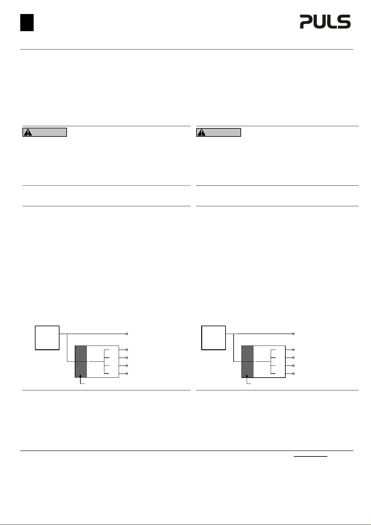
typical wiring configuration is shown below. All sensitive loads are connected directly to the power
supply. If needed, these load circuits can be protected with standard circuit breakers or fuses. Loads
which are less sensitive to voltage dips or interruptions or which are the source of the voltage drop
themselves are connected to the output of the PISA protection module.
Vor Inbetriebnahme lesen!
Bitte lesen Sie diese Warnungen und Hinweise sorgfältig durch, bevor Sie das Gerät in Betrieb
nehmen. Bewahren Sie die Anleitung zum Nachlesen auf. Das Gerät darf nur durch
fachkundiges und qualifiziertes Personal installiert werden. Bei Funktionsstörungen oder
Beschädigungen schalten Sie sofort die Versorgungsspannung ab und senden das Gerät zur
Überprüfung ins Werk. Das Gerät beinhaltet keine Servicebauteile.
Die angegebenen Daten dienen allein der Produktbeschreibung und sind nicht als zugesicherte
Eigenschaften im Rechtssinne aufzufassen. Im Zweifelsfall gilt der englische Text.
Bestimmungsgemäßer Gebrauch: Diese Gerät ist für den Einbau in ein Gehäuse konzipiert
und zur Verwendung für allgemeine elektronische Geräte, wie z.B. Industriesteuerungen,
Bürogeräte, Kommunikation sgeräte oder Messgeräte geeignet. Benutzen Sie dieses Gerät nicht
in Steuerungsanlagen, in denen eine Funktionsstörung zu schweren Verletzungen führen oder
Lebensgefahr bedeuten kann.
WARNUNG
Missachtung nachfolgender Punkte kann einen elektrischen Schlag, Brände, schwere Unfälle
oder Tod zur Folge haben.
1) Schalten Sie die Eingangsspannung vor Installations-, Wartungs- oder Änderungsarbeiten ab
und sichern Sie diese gegen unbeabsichtigtes Wiedereinschalten.
2) Sorgen Sie für eine ordnungsgemäße und fachgerechte Verdrahtun g .
3) Führen Sie keine Änderungen oder Reparaturversuche am Gerät durch.
4) Gerät niemals öffnen.
5) Verhindern Sie das Eindringen von Fremdkörpern, wie z.B. Büroklammern und Metallteilen.
6) Betreiben Sie das Gerät nicht in feuchter Umgebung oder in einer Umgebung, bei der mit
Betauung oder Kondensation zu rechnen ist.
Gerätebeschreibung
Das PISA Sicherungsmodul erfüllt zwei grundlegende Aufgaben: Einerseits verteilt es den Strom
eines leistungsstarken Netzgerätes auf vier strombegrenzte NEC-CLASS-2 Ausgänge, reduziert
damit den Verkabelungsaufwand und ermöglicht einen einfacheren Zulassungsprozess der
gesamten Anlage oder Maschine. Andererseits lässt es nur soviel Strom am Ausgang zu, dass
die Eingangsspannung nicht unter 21V abfällt. Damit wird eine sichere und unterbrechungsfreie
Versorgung für empfindliche Verbraucher (wie z.B. Steuerungen und Sensoren) möglich, wenn
diese an die gleiche Stromversorgung wie das PISA Sicherungsmodul selbst angeschlossen
werden.
Das Sicherungsmodul hat einen 24V-Eingang und vier Ausgänge, auf die der Strom verteilt wird.
Jeder Ausgangskanal ist mit einer redundanten elektronischen Überstromschutzeinrichtung
ausgestattet, welche eine Überlastung von Ausgangsleitungen verhindert.
Wird ein zulässiger Kanalstrom oder der Gesamtstrom für das Sicherungsmodul überschritten,
begrenzt das Modul die Ausgangsströme und schaltet danach alle vier Ausgänge ab.
Ein Schutzschild in der Eingangsstufe des PISA Moduls arbeitet dabei wie ein regelbares Ventil
und lässt nur so viel Strom durch, dass die Versorgungsspannung nicht unter 21V absinkt. Ein
Unterschreiten dieser Schwelle könnte zum Beispiel wegen eines zu schwach ausgelegten
Netzgerätes, einer Überlast oder eines zu hohen Einschalt- oder Anlaufstromes auftreten.
In solchen Fällen werden alle Ausgänge für eine kurze Zeit aktiv strombegrenzt gefolgt von einer
bschaltung aller vier Ausgangskanäle.
In einer typischen Konfiguration, wie unten gezeichnet, werden die empfindlichen Verbraucher
möglichst direkt an die Stromversorgung angeschlossen. Bei Bedarf können hier StandardLeitungsschutzschalter zur Absicherung verwendet werden. Verbraucher, die unempfindlich auf
kurze Spannungsunterbrechungen reagieren oder selbst die Ursache für Einbrüche auf der 24VVersorgung sind, werden an den Ausgängen des Sicherungsmoduls angeschlossen.
PISA11.CLASS2
DC 24V
Power
Supply
PISA Protection Module
Safeguard
Non NEC-CLASS 2 Load
NEC CLASS 2 Circuit 1A1
NEC CLASS 2 Circuit 2
A2
NEC CLASS 2 Circuit 3
A3
NEC CLASS 2 Circuit 4
A4
DC 24V
Netzgerät
PISA Sicherungsmodul
A2
A3
A4
Schutzschild
Kein NEC-CLASS-2 Stromkreis
NEC-CLASS-2 Stromkreis 1A1
NEC-CLASS-2 Stromkreis 2
NEC-CLASS-2 Stromkreis 3
NEC-CLASS-2 Stromkreis 4
Germany +49 89 9278 0 www.pulspower.de Headquarters:
China +86 512 62881820 www.pulspower.cn
France +33 478 668 941 www.pulspower.fr
North America +1 630 587 9780 www.pulspower.us
Austria +43 27 64 32 13 www.pulspower.at
Singapore +65 6684 2310 www.pulspower.sg
PULS GmbH
Arabellastrasse 15
D-81925 Munich
Germany
www.pulspower.com
Switzerland +41 56 450 18 10 www.pulspower.ch
United Kingdom +44 845 130 1080 www.pulspower.co.uk
Page 2
PISA11.CLASS2 Instruction Manual
PISA11.CLASS2 Bedienungsanleitung
Technical Data 1) Technische Daten
1)
PISA11.CLASS2
Rated Voltage Nennspannung nom. DC 24V
Input Voltage Range Eingangsspannungsbereich 18-30Vdc
Maximum Input Voltage 2) Maximale Eingangsspannung
2)
max. 30Vdc
Input current Eingangsstrom nom. 15A
Required Input Voltage for Turning-on of
Outputs
Turn-on Delay of Outputs
14)
Einschaltverzögerung der Ausgänge
Erforderliche Eingangsspannung zum
Einschalten der Ausgänge
typ. 21.4Vdc
14)
typ. 270ms
Outputs meets NEC CLASS 2 Ausgänge erfüllen NEC-CLASS-2 Yes / Ja
Input Voltage Protection Level 3) Aktivierung der Eingangsschutzschaltung 3) min. / max. 21.0Vdc / 21.8Vdc
Output Current 7) Channel 1
Channel 2
Channel 3
Channel 4
Total Output Current (all 4 channels) Gesamter Ausgangsstrom (alle 4 Kanäle) nom. 14.8A at 24V, 12.8A at 28V
Output Current Limitation
Shutdown Times
12)
Ausgangsstrombegrenzung
13)
at 2x rated current Abschaltzeiten
at short circuit bei Kurzschluss typ. 10ms
Voltage Drop between Input and Output 4) Spannungsabfall zwischen Ein- und Ausgang
Ausgangsstrom 7) Kanal 1
Kanal 2
Kanal 3
Kanal 4
12)
13)
min. / max. 16.6A / 23.6A
bei 2x Nennstrom typ. 1s at 7.4A
nom.
nom.
nom.
nom.
4)
3.7A at 24V, 3.2A at 28V
3.7A at 24V, 3.2A at 28V
3.7A at 24V, 3.2A at 28V
3.7A at 24V, 3.2A at 28V
typ. 92mV at 24V, 81mV at 28V
Stand-by Current Ruhestrom typ. 43mA
Power Losses in Stand-by Mode Verlustleistung im Leerlauf typ. 1.0W
Power Losses at typical Output Loads 4) Verlustleistung bei typ. Ausgangsströmen 4) typ. 1.6W
Max. Load Capacitors 5) per channel Max. Lastkapazität 5) pro Kanal typ. / min. 58mF / 14mF
four outputs in total alle 4 Ausgänge zusammen typ. / min. 58mF / 14mF
Max. Load Capacitors 6) per channel Lastkapazität pro Kanal 6) typ. / min. 68mF / 45mF
Degree of Pollution (non-conductive) Verschmutzungsgrad (nicht leitend) EN 50178 / 62103 2
Degree of Protection Schutzart EN 60529 IP20
Class of Protection Schutzklasse IEC 61140 III
Reverse Polarity Protection (Input) Verpolschutz am Eingang No / Nein
Return Voltage Resistance 9) Rückspeisefestigkeit
9)
max. 30Vdc
Parallel Use of Outputs Parallelschaltung von Ausgängen No / Nein
Operational Temperature Range Betriebstemperaturbereich nom. -25°C - +70°C
Storage Temperature Range Lagertemperaturbereich nom. -40 °C - +85°C
Humidity
10)
Feuchte
10)
IEC 60068-2-30 5 - 95% r.H.
Vibration Schwingen IEC 60068-2-6 2g
Shock Schocken IEC 60068-2-27 30g 6ms, 20g 11ms
Dimensions
11)
(WxHxD) Abmessungen
11)
(BxHxT) nom. 45 x 75 x 91mm
Weight Gewicht max. 120g, 0.26lb
Limited Warranty Gewährleistung Years / Jahre 3
1) All parameters are specified at 24Vdc, 25°C ambient temperature and after a 5 minutes run-in
time unless otherwise noted.
2) Absolute maximum continuous input voltage with no damage to the protection module.
3) Once the voltage tries to fall below this value, a protection circuit limits or shutdown the outputs in
order to maintain sufficient supply voltage. Voltage dips below this value can occur up to 200µs.
4) Typical value when all output channels are loaded with 50% of its nominal current.
5) Permissible capacitor, which can be connected to the outputs without shutdown of the protection
module. The listed values are valid for the entire temperature range.
Typical values are with an additional 1.9A resistive load per output
Minimum values are with an additional 3.7A constant current load per output
6) Permissible capacitor, which can be connected to one particular output when only this output is
loaded and all others are not. The listed values are valid for the entire temperature range.
Typical values are with an additional 1.9A resistive load
Minimum values are with an additional 3.7A constant current load
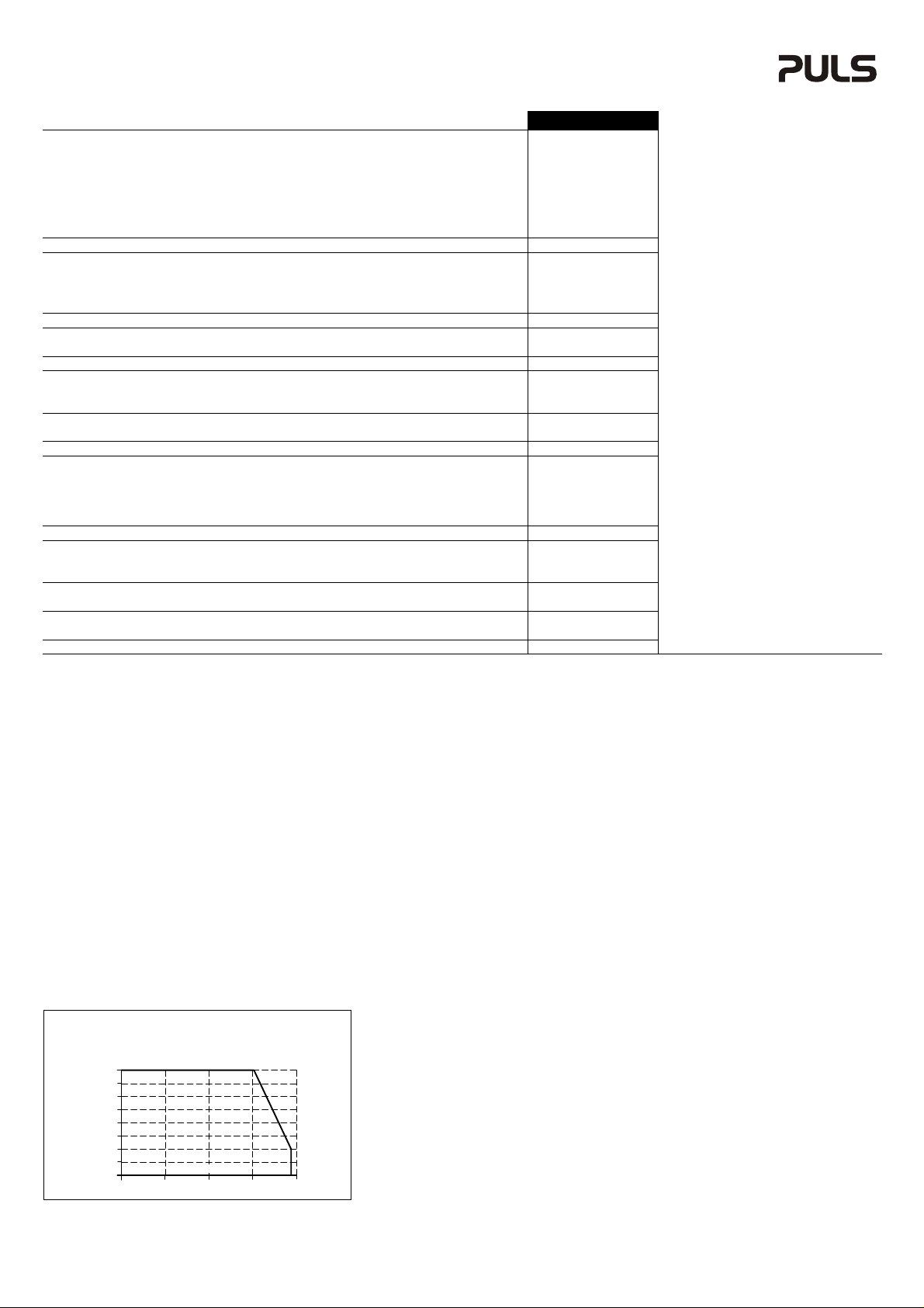
7) See also Fig. A
8) Not used
9) Loads such as decelerating motors and inductors can feed voltage back to the output of the PISA
module. The figure represents the maximum allowed feed-back voltage.
10) Do not energize while condensation is present.
11) Depth without DIN-rail and signal connector. Add 13mm in depth for the signal connector.
12) Provided that the supplying power source can deliver enough current. This current can be drawn
from each individual output for a short period of time.
13) The “timer” for shutdown starts immediately once the nominal current levels are exceeded. All
output channels will shutdown, if one channel is overloaded. See Fig. 5 for more values.
14) All outputs turn on at the same time.
Ausgangsstrom in Abhängigkeit der Versorgungsspannung
Input Voltage
Fig. A / Bild A
Output current vs. supply voltage /
1) Alle Werte gelten bei 24Vdc, 25°C Umgebungstemperatur und nach einer Aufwärmzeit von 5
Minuten, wenn nichts anderes angegeben ist.
2) Absolute Obergrenze, bei der das Sicherungsmodul noch nicht zerstört wird.
3) Unterhalb dieser Eingangsspannung wird die Schutzschaltung aktiviert (verzögert um 200µs),
um einen Einbruch der Versorgungsspannung zu vermeiden. Die Ausgangsströme werden
für eine bestimmte Zeit begrenzt und danach abgeschaltet.
4) Typischer Wert, wenn alle Ausgänge mit 50% des Nennstroms belastet werden.
5) Zulässige Gesamtkapazität, die an den vier Ausgängen zugeschaltet werden kann ohne
Abschaltung des Moduls. Die Werte gelten für den gesamten Temperaturbereich.
Die typischen Werte gelten mit einer zusätzlichen Widerstandslast von 1,9A pro Ausgang
Die Minimumwerte gelten mit einer zusätzlichen Konstantstromlast von 3,7A pro Ausgang.
6) Zulässige Kapazität, die an einem Ausgang zugeschaltet werden kann, wenn alle anderen
Ausgänge unbelastet sind. Die Werte gelten für den gesamten Temperaturbereich.
Die typischen Werte gelten mit einer zusätzlichen Widerstandslast von 1,9A.
Die Minimumwerte gelten mit einer zusätzlichen Konstantstromlast von 3,7A.
7) Siehe auch Bild A
8) frei
9) Bremsende Motoren oder Induktivitäten können Spannung zum Ausgang des PISA Moduls
rückspeisen. Der Wert gibt die maximal zulässige Rückspeisespannung an.
10) Nicht betreiben, solange das Gerät Kondensation aufweist.
11) Tiefe ohne DIN-Schiene und Signalstecker. Zusätzlich 13mm in der Tiefe für Signalstecker.
12) Vorausgesetzt, die speisende Stromversorgung kann genügend Strom liefern. Dieser Strom
kann kurzzeitig aus jedem einzelnen Ausgangskanal entnommen werden.
13) Der „Timer“ zur Abschaltung startet bei Überschreitung des Nennstroms. Bei Überlast an
einem Kanal werden alle Kanäle abgeschaltet. Siehe auch Bild 5 für weitere Werte.
14) Alle Ausgänge schalten gleichzeitig ein.
30V
29V
28V
27V
26V
25V
24V
23V
22V
01A 3A4A
Output Current, typ
2A
Page 3
PISA11.CLASS2 Instruction Manual
A
A
A
A
A
A
A
A
PISA11.CLASS2 Bedienungsanleitung
Installation
This protection module is suitable for DIN-rail mounting. Use DIN-rail according to EN 60715 or EN
50022 with a height of 7.5 or 15mm.
Keep the following installation clearances:
Top and bottom: min. 40mm on top, 20mm on the bottom
Left and right: min. 6.4mm if the ambient temperature is above 60°C.
The protection module can be used with any regulated 24Vdc power supply. If the power source can
deliver more than 40A continuous, the PISA module shall be equipped with an external input fuse
(e.g. 30/32A). The power capability and performance of the power supply can limit the output
characteristics of the PISA module.
Make sure that the input voltage polarity is correct before applying the input voltage.
Do not connect batteries to the outputs of the PISA module.
high voltage drop between the power supply and the protection module might cause a
malfunction. It is not recommended to use wires longer than 2x2m (for 2.5mm2 wires or AWG 14) or
2x4m (for 4mm2 wires or AWG 12) to avoid undesired undervoltage conditions on the input of the
protection module.
Use an appropriate wire size on the input, which matches the ampacity of the power supply.
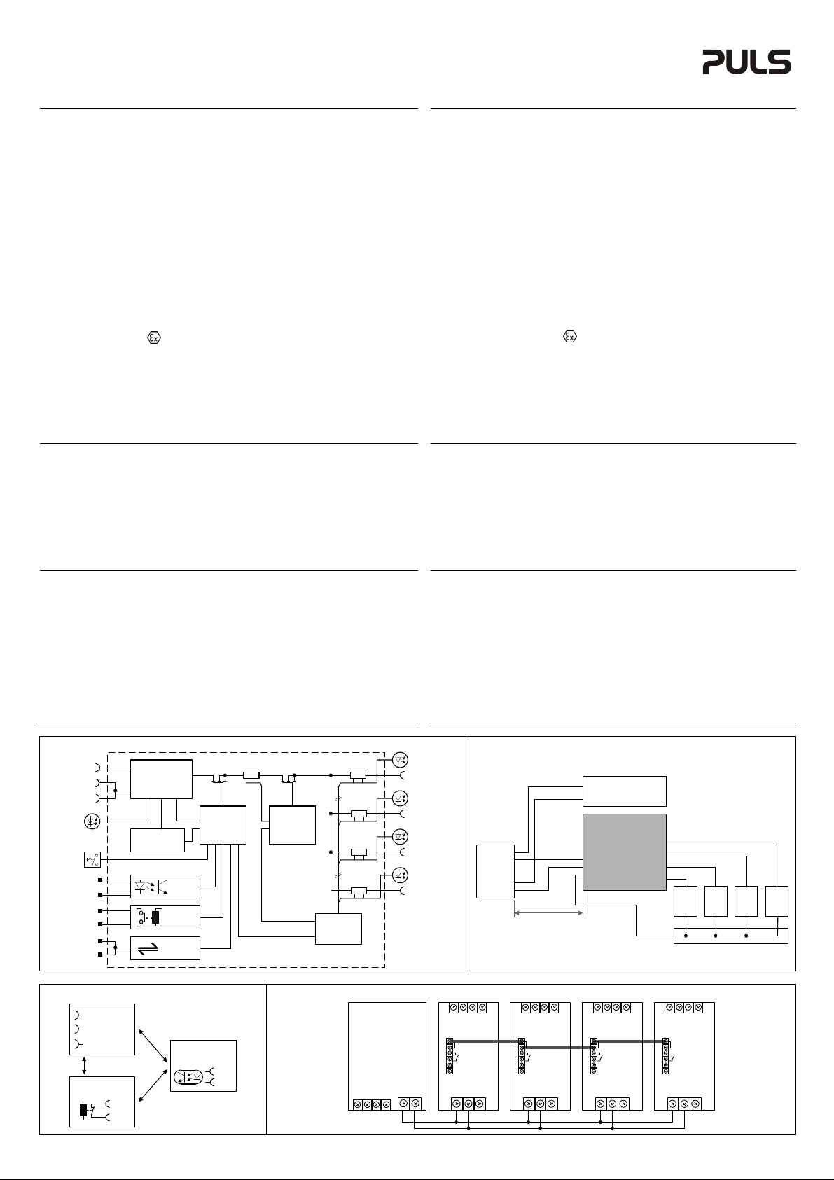
wiring scheme can be found in Fig. 2.
Use in hazardous location areas
Units which are marked with "Class I Div 2" are suitable for use in Class I Division 2 Groups A, B, C,
D locations.
Units which are marked with II 3G Ex nA nC IIC T4 Gc are suitable for use in Group II Category
3 (Zone 2) environments and are evaluated according to EN 60079-0:2009 and EN 60079-15:2010.
WARNING EXPLOSION HAZARDS!
Substitution of components may impair suitability for this environment. Do not disconnec t the unit or
operate the reset button unless power has been switched off or the area is known to be nonhazardous. The signal-connector may not be used in hazardous location areas unless additional
measures are met to avoid an unintended disconnection (e.g. an additional mechanical fixation).
The connection must meet the requirements of the EN 60079-15:2010. A suitable enclosure must be
provided for the end product which has a minimum protection of IP54 and fulfils the requirements of
the EN 60079-15:2010.
Synchronization of Multiple PISA Modules (see Fig. 4)
If multiple PISA modules are used on the same power supply, it is recommended to connect the
sync. bus of all modules together. If one unit shuts down due to the protection function of the input
voltage protection circuit (safeguard), all other modules will shutdown too. This avoids a false
interpretation of which output channel caused the problem. If the sync. terminals are not linked, the
module with the highest safeguard protection voltage level (caused by tolerances) would shutdown
first regardless whether the failure was caused by this module or not.
Please note:
If the cause for the shutdown was an over-current of one individual channel, only this module will
shutdown and the other modules will stay on. In this case the sync. line has no impact on the other
modules.
Dielectric Strength (see Fig. 3)
The relay contact and the ON/OFF signal are floating and separated from the input and output
voltage. The creepage and clearance between the power port and the signal port is 1.3mm. The
following isolations test were performed:
A B C
Type Test (60s) 500Vac 500Vac 50Vac
Factory Test (5s) 500Vac 500Vac Field Test (5s) 500Vac 500Vac 50Vac
Cut-off current setting >1mA >1mA >1mA
Type and factory tests are conducted by the manufacturer. Field tests may be conducted in the field
using the appropriate test equipment which applies the voltage with a slow ramp (2s up and 2s
down). Connect all input and output terminals together as well as all signal poles before conducting
the tests. When testing, set the cut-off current settings to the value in the table above.
Input
Input
Status
Reset,
ON/OFF
Reset,
ON/OFF
OutputsOK
Contact
Sync.
+
-
-
12
11
13
14
15
16
Fig. 1 / Bild 1 Functional diagram / Funktionsschaltbild Fig. 2 / Bild 2 Wiring scheme / Verdrahtungsplan
I
Output
Current
Monitor
Sense
I
Sense
I
Sense
I
Sense
Safeguard for
Minimum Input
NEC-CLASS-2
Controller
(+)
(-)
Voltage
Reset,
ON/OFF
Output
OK
Synchro-
nization
Current
Limiter &
Shut-down
Manager
I
Sense
Redundant
Emergency
Switch
Fig. 3 / Bild 3 Isolation Fig. 4 / Bild 4 Using multiple PISA modules in parallel / PISA Module im Parallelbet rieb
Installation
Das Gerät ist zur Montage auf DIN-Schienen entsprechend EN 60715 oder EN 50022 mit einer
Höhe von 7,5 oder 15mm geeignet und kann mit beliebigen geregelten 24Vdc
Stromversorgungen verwendet werden. Bei Stromversorgungen mit Dauerausgangsströmen
über 40A muss am Eingang eine externe Sicherung (z.B. 30/32A) vorgeschaltet werden. Die
Eigenschaften und Leistungsfähigkeit der Stromversorgung können die Ausgangsparameter des
PISA Moduls einschränken.
Folgende Mindestabstände sind bei der Installation einzuhalten:
Oben mindestens 40mm und unten mindestens 20mm
Links und rechts: min. 6.4mm bei Umgebungstemperaturen über 60°C.
uf korrekte Polarität der Eingangsspannung ist zu achten.
Keine Batterien direkt an den Ausgang der PISA Module anschließen.
Zu hohe Spannungsabfälle zwischen der Stromversorgung und dem Sicherungsmodul können
Fehlfunktionen verursachen. Wir empfehlen, keine Leitungen länger als 2x2m (bei 2.5mm2
Querschnitt) oder 2x4m (bei 4mm2), um das Sicherungsmodul mit ausreichend Spannung zu
versorgen.
Die Auslegung des Drahtquerschnitts der Eingangsleitung muss dem Amperewert der
Stromversorgung angepasst sein. Ein Anschlussdiagramm ist in Bild 2 gezeigt.
Betrieb in explosionsgefährdeter Umgebung
Geräte, die mit "Class I Div 2" gekennzeichnet sind, sind für den Einsatz in Klasse I Division 2
Gruppen A,B,C,D Umgebung geeignet.
Geräte, welche die Kennzeichnung II 3G Ex nA nC IIC T4 Gc tragen, sind nach EN 60079-
0:2009 und EN 60079-15:2010 getestet und können in einer Gruppe II, Kategorie 3 (Zone 2)
Umgebungen verwendet werden.
CHTUNG EXPLOSIONSGEFAHR!
Veränderungen am Gerät können die Tauglichkeit für diese Umgebung beeinträchtigen.
nschlüsse nicht abklemmen und Reset Taste nicht betätigen, solange Spannung anliegt oder
die Umgebung als explosionsgefährlich gilt. Der Signalstecker darf in Bereichen mit
gasexplosionsfähiger Atmosphäre nicht angeschlossen sein, außer es werden Maßnahmen
getroffen, die ein unbeabsichtigtes Trennen verhindern (zusätzliche mechanische Sicherung).
Das Gerät muss mindestens in ein IP54 Gehäuse, die den Anforderungen der EN60079-15:2010
entspricht, eingebaut werden. Die Anschlüsse müssen ebenfalls dieser Norm entsprechen.
Synchronisation mehrerer PISA Module (siehe Bild 4)
Wenn mehrere PISA Module von einer Stromversorgung versorgt werden, sollten die Sync.-
nschlüsse der einzelnen Module miteinander verbunden werden. Damit werden alle PISA
Module abgeschaltet, wenn bereits bei nur einem Modul die Eingangsschutzschaltung
angesprochen hat. Das vermeidet eine Fehlinterpretation bei der Ursachensuche. Sind die
Sync.- Anschlüsse der einzelnen PISA Module nicht miteinander verbunden, schaltet das PISA
Modul mit dem höchsten Spannungswert der Eingangsspannungsschutzschaltung (bedingt
durch unterschiedliche Toleranzen der einzelnen Module) als Erstes ab, unabhängig ob der
Verursacher an diesem Modul angeschlossen ist oder nicht.
Bitte beachten: Liegt der Grund einer Abschaltung bei der Überschreitung eines Kanalstroms,
schaltet nur das betroffene PISA Modul die Ausgänge ab. Weitere mit der Sync.-Leitung
verbundenen Module bleiben an.
Isolationsfestigkeit (siehe Bild 3)
Der Relaiskontakt und der „ON/OFF“-Signaleingang haben keinen Bezug zur Eingangs- oder
usgangsspannung. Die Luft- und Kriechstrecken zwischen Leistungs- und Signalklemmen
betragen 1,3mm. Die folgenden Isolationstests wurden durchgeführt:
A B C
Typprüfung (60s) 500Vac 500Vac 50Vac
Stückprüfung (5s) 500Vac 500Vac Wiederholungsprüfung (5s) 500Vac 500Vac 50Vac
Strom-Abschaltschwelle >1mA >1mA >1mA
Typ- und Stückprüfungen werden beim Hersteller durchgeführt. Wiederholungsprüfungen dürfen
mittels geeigneten Prüfgenerators mit langsam (2s) ansteigenden und abfallenden
Spannungsrampen in der Anwendung erfolgen. Vor den Tests sind alle Eingangs und
usgangspole wie auch alle Signalkontakte miteinander zu verbinden. Während der Tests darf die
Strom-Abschaltschwelle nicht kleiner als der in der obigen Tabelle angegebene Wert sein.
Failure
+ Output 1
Failure
+ Output 2
Failure
+ Output 3
Failure
+ Output 4
24V
Power
Supply
+
+
-
-
Recommended
wire length:
4mm²: max. 2x4m
2.5mm²: max.2x2m
PLC, Controls
+
(sensitive loads)
-
PISA
Protection Module
+
-
I/P
-
O/P 1
O/P 2
O/P 3
O/P 4
Distribution
Node
+
Load
4
+
+
Load
Load
3
2
-
-
-
+
Load
1
-
Input +, Output
(1 - 4)
Sync.
(15,16)
A
Output-ok
Contact
13
14
B
Reset, ON/OFF
C
Signal Input
+
12
-
11
QT40.241
Power
Supply
Input
L1 L2 L3 PE
Output
+
1 2 3 4
Outputs
PISA11
16
sync.
15
14
OK
13
12
+
Reset
11
-
Input
+
- -
-
16
15
14
13
12
11
1 2 3 4
Outputs
PISA11
sync.
OK
+
Reset
-
Input
- -
+
16
15
14
13
12
11
1 2 3 4
Outputs
PISA11
sync.
OK
+
Reset
-
Input
- -
+
16
15
14
13
12
11
1 2 3 4
Outputs
PISA11
sync.
OK
+
Reset
-
Input
- -
+
Page 4
PISA11.CLASS2 Instruction Manual
A
A
PISA11.CLASS2 Bedienungsanleitung
CE Marking
CE mark is in conformance with EMC directive 2004/108/EC, the low-voltage directive (LVD)
2006/95/EC and the RoHS directive 2011/65/EU.
EMC Immunity: EN 61000-6-1, EN 61000-6-2
EMC Emission EN 61000-6-3, EN 61000-6-4, FCC Part 15 Class B
Terminals and Wiring
Use appropriate copper cables that are designed for minimum operating temperatures of:
60°C for ambient up to 45°C and minimum
75°C for ambient up to 60°C and minimum
90°C for ambient up to 70°C.
Follow national installation codes and regulations! Ensure that all strands of a stranded wire enter
the terminal connection! Ferrules are allowed. Unused terminal must be closed.
Further wiring requirements are listed in the chapter “Installation” of this document.
Power terminals Signals terminals
Solid wire 0.2-6mm
Stranded wire 0.2-4mm
American Wire Gauge 20-10 AWG 24-16 AWG
Wire stripping length 7mm / 0.28inch 6mm / 0.24inch
Tightening torque 0.8Nm, 7lbs.in 0.35Nm, 3lbs.in
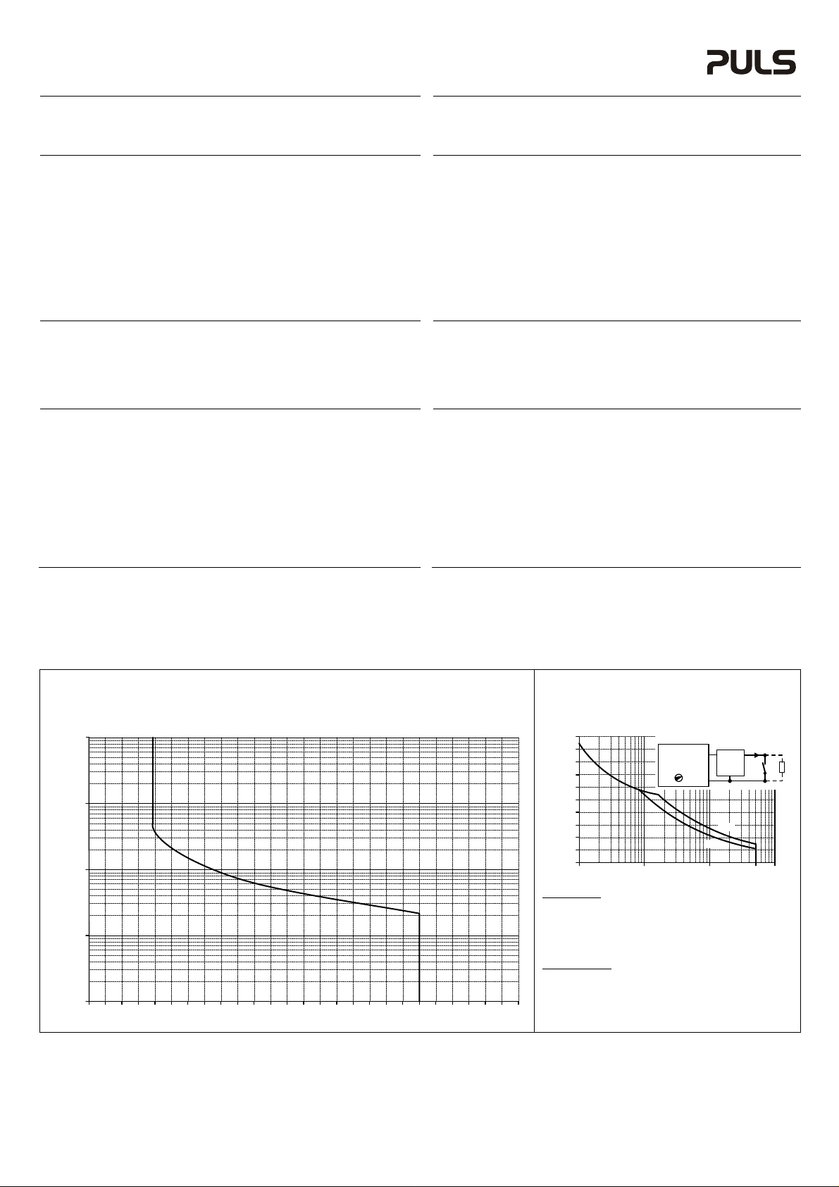
Current limitation and Shutdown Behavior of the Individual Outputs (see Fig. 5)
The total output current (sum of all four channels) of the protection module is typically limited to the
ampere value which is mentioned as “output current limitation” in the technical tables. This current
can be drawn from each individual output.
The shutdown times can be found in the technical data table or in Fig. 5.
Please note: The protection module has a common shutdown element for all four outputs. An
overload or over-current on one output will result in a shutdown of all four output channels.
Input Voltage Protection Circuit (Safeguard protection circuit, see Fig. 6)
The input voltage protection circuit can further limit the max. output current. The protection module
only permits so much current on the outputs that the input voltage of this unit (which corresponds to
the output voltage of the power supply) does not fall below 21V. This ensures a reliable supply
voltage for sensitive equipments, such as PLCs, controls or sensors, when they are connected
directly to the same power supply as the PISA protection module.
When the power supply can not deliver enough current to support all loads without bringing the
power supply into an overload mode followed by an output voltage drop, the input voltage protection
circuit (safeguard) limits the output current. This safeguard circuit acts like a valve only permitting so
much current so that the supply voltage does not fall below 21V. The period of time for how long the
protection circuit is able to actively limit the current depends on the difference between input and
output voltage and the current which flows through the PISA protection module. After this period, all
outputs will be shutdown.
Shutdown times for a short circuit condition across the outputs can be found in Fig. 6.
Shutdown Time, typ.
100s
10s
1s
100ms
10ms
0
246810121416 18 20 22 24 26A135791113151719212325
2
2
Fig. 5 / Bild 5
Shutdown curve / Auslösekennline
0.2-1.5mm2
0.2-1.5mm2
CE Kennzeichnung
Das CE Zeichen ist angebracht und erklärt die Erfüllung der EMV Richtlinie 2004/108/EG, der
Niederspannungsrichtlinie 2006/95/EG und der RoHS Richtlinie 20 11 /65/EU.
Störfestigkeit: EN 61000-6-1, EN 61000-6-2
Störaussendung: EN 61000-6-3, EN 61000-6-4, FCC Part 15 Klasse B
Anschlussklemmen und Verdrahtung
Verwenden Sie geeignete Kupferkabel, die mindestens für
60°C bei Umgebungstemperaturen bis zu 45°C und
75°C bei Umgebungstemperaturen bis zu 60°C und
90°C bei Umgebungstemperaturen bis zu 70°C zugelassen sind.
Beachten Sie nationale Bestimmungen und Installationsvorschriften! Stellen Sie sicher, dass
keine einzelnen Drähte von Litzen abstehen. Aderendhülsen sind erlaubt. Nichtbenutzte
Klemmen zudrehen.
Weitere Verdrahtungsanforderungen befinden sich im Kapitel „Installation“ dieses Dokuments.
Leistungsanschlüsse Signalanschlüsse
Starrdraht 0,2-6mm
Litze 0,2-4mm
AWG 20-10 AWG 24- 16 AWG
Abisolierlänge 7mm / 0,28inch 6mm / 0,24inch
Anzugsdrehmoment 0,8Nm, 7lbs.in 0,35Nm, 3lbs.in
Strombegrenzung und Abschaltezeiten der einzelnen Ausgänge (siehe Bild 5)
Der Summenausgangsstrom des Moduls ist aktiv auf den Wert der Ausgangsstrombegrenzung
(siehe Tabelle mit technischen Angaben) begrenzt. Dieser Strom kann auch aus jedem
einzelnen Ausgangskanal entnommen werden. Abschaltzeiten findet man in der Tabelle mit den
technischen Angaben sowie in Bild 5.
Bitte beachten: Das Sicherungsmodul besitzt ein gemeinsames Abschaltelement für alle vier
usgänge. Ein Überstrom oder eine Überlastung eines einzelnen Ausgangs hat ein Abschalten
aller vier Ausgänge zur Folge.
Eingangsspannungsschutzschaltung (Schutzschild-Schaltung, siehe Bild 6)
Die Eingangsspannungsschutzschaltung kann den maximalen Ausgangsstrom zusätzlich
einschränken. Das Sicherungsmodul lässt nur soviel Strom am Ausgang zu, dass die
Eingangsspannung (diese entspricht der Ausgangsspannung der Stromversorgung) nicht unter
21V abfällt. Damit wird eine sichere und unterbrechungsfreie Versorgung für empfindliche
Verbraucher (wie z.B. Steuerungen und Sensoren) erreicht, wenn diese an die gleiche
Stromversorgung wie das PISA Sicherungsmodul selbst angeschlossen werden.
Wenn die Stromversorgung nicht genügend Strom zur Versorgung aller Lasten liefern kann und
in den Überlastmodus mit nachfolgendem Spannungseinbruch gehen würde, begrenzt die
Eingangsspannungsschutzschaltung (PISA Schutzschild) den Ausgangsstrom. Dieses
„Schutzschild“ arbeitet wie ein regelbares Ventil und lässt nur soviel Strom durch, dass die
Versorgungsspannung nicht unter 21V abfällt. Die Dauer dieser Begrenzung hängt von der
Differenz der Eingangs- zur Ausgangsspannung sowie dem Strom durch das PISA Modul ab.
Wird die Zeit überschritten, erfolgt eine Abschaltung aller Ausgänge.
bschaltzeiten bei Kurzschluss am Ausgang in Abhängigkeit des Stromes findet man in Bild 6.
Output Current typ.
2
2
Time in current limiting mode until the outputs will shutdown /
Strombegrenzungsdauer bis zur Abschaltung der Ausgänge
Output Current / Ausgangsstrom, typ.
(Sum-current of all output channels - I
20A
18A
16A
14A
12A
0,2-1,5mm2
0,2-1,5mm2
Fig. 6 / Bild 6
Test Setup
Adjustable
Power
Supply
I
OUT
)
I
PISA
Module
OUT
Short
+
OUT
-
10A
8A
6A
4A
2A
10ms
Test procedure:
1. Set current of the adjustable power supply to the test current.
2. Set load to 80% of the test current and wait for a thermally stable
condition.
3. Short circuit the output of the PISA module and measure the time until
the outputs shutdown.
The output current is the sum of all outputs. No single output channel is
allowed to be overloaded.
Testdurchführung:
1. Ausgangsstrom des Netzgerätes auf den Teststrom einstellen.
2. Laststrom auf 80% des Teststroms einstellen und thermisch
eingelaufenen Zustand abwarten.
3. Ausgang des PISA Moduls kurzschließen und Zeit bis zur Abschaltung
messen.
Der Ausgangsstrom ist die Summe aller Ausgänge. Kein einzelner PISA
Ausgang darf überlastet sein.
100ms 1s 10s
Shutdown Time / Zeit bis zur Abschaltung
20°C
45°C
5s
Load
=80%
Page 5
PISA11.CLASS2 Instruction Manual
A
A
PISA11.CLASS2 Bedienungsanleitung
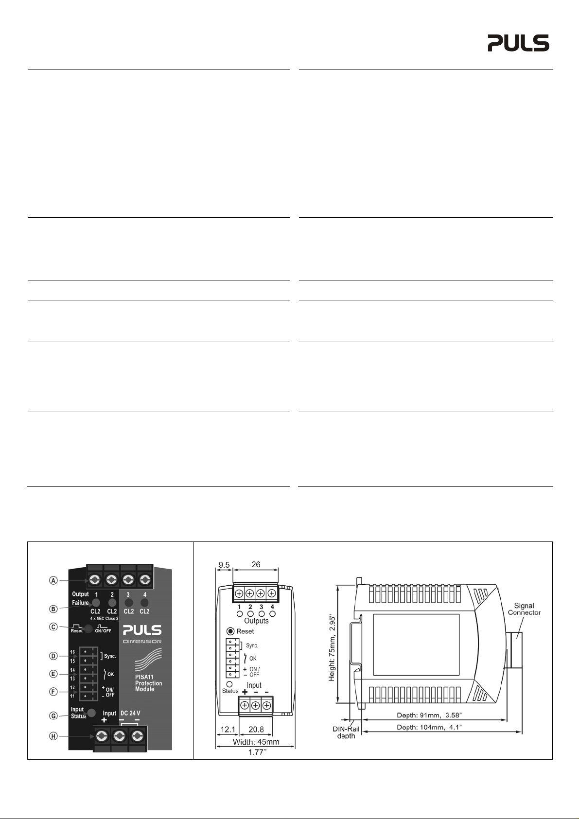
Red Failure LEDs (see Fig. 7-B)
The red LEDs are failure indicators. Any time a red LED is on or blinking, the outputs have
shutdown.
Three reasons why the outputs have been shutdown:
1) The output current of one or more individual output channels was too high.
In this case, the affected output channel LED is blinking and all others are illuminated.
2) The sum of the output current of all four output channels was exceeded.
In this case, all red LEDs are blinking.
3) The outputs needed to be shutdown in order to maintain sufficient input voltage.
In this case, all red LEDs are on and the green LED is blinking.
The outputs can also be turned off by pushing the ON/OFF button on the front of the unit or by
applying an external signal to the ON/OFF signal input. In this case, all red LEDs are on.
Outputs which have shutdown must be turned on manually by pushing the reset button or by an
external reset signal (ON/OFF signal input). A cycling of the input power does not reset the unit. The
failure signals are stored until a reset is intentionally initiated.
When LED 1 and 4 as well as the LEDs 2 and 3 are alternately blinking, an internal error has
occurred. Try to reset the unit by pushing the reset button. If this does not help, ship the unit to the
factory for inspection.
Reset and ON/OFF Button (see Fig. 7-C)
This is a pushbutton which can be used for two purposes:
1) In a failure mode (outputs have shutdown), the outputs can be turned on again by pushing and
holding the reset button for more than 1 second.
2) In normal mode (outputs have not shutdown), a short (> 50ms) push will turn all outputs ON or
OFF.
The unit will be shipped (factory setting) with the outputs turned-on. The ON/OFF function has no
safety feature included.
Synchronization of Multiple PISA Modules (see Fig. 7-D)
See description on the previous pages.
Output-OK Relay Contact (see Fig. 7-E)
This relay contact is closed when the input voltage is sufficient and the outputs are not shutdown.
Contact closes when the input voltage rises above 21Vdc typically and all output channels are on.
Contact ratings: max. 30Vdc 1A, 30Vac 0.5A, resistive load, min. current 1mA
ON/OFF (Inhibit) and Reset Input (see Fig. 7-F)
This input signal is galvanically isolated with an integrated optocoupler and works in the same
manner as the reset and ON/OFF button.
In a failure mode (outputs have shutdown), the outputs can be turned on again by applying a voltage
for more than 1 second.
In normal mode (outputs have not shutdown), a short (> 50ms) voltage pulse will turn all outputs ON
or OFF. The ON/OFF function has no safety feature included.
Signal voltage for activation: min. 10V, max. 30V. Required signal current: < 6mA.
Green Input Status LED (see Fig. 7-G)
This LED monitors the input voltage. The green LED is illuminated if the input voltage is higher than
21Vdc. The green LED will blink when the input protection circuit (Safeguard) is activated in order to
protect the supply voltage from dropping below 21V or when the outputs have already been
shutdown due to a low input voltage.
Once the outputs have shutdown, a reset procedure similar to the one for the red LEDs is required.
reset is not necessary when the green LED is blinking and the outputs have not been shutdown.
In this case the blinking LED will turn solid once the input voltage is sufficient again.
Fig. 7 / Bild 7
User elements / Bedienelemente
Rote Fehler-LEDs (siehe Bild 7-B)
Die roten LEDs sind Fehleranzeigen. Wenn eine LED blinkt oder leuchtet wird signalisiert, dass
die Ausgänge abgeschaltet haben.
Drei Gründe, warum die Ausgänge abgeschaltet haben könnten:
1) Der Ausgangsstrom eines Ausgangskanals war zu hoch. Es blinkt die LED, deren Kanal die
Abschaltung verursacht hat.
2) Die maximale Summenstrom aller 4 Ausgangskanäle wurde überschritten. In diesem Fall
blinken alle vier LEDs.
3) Die Ausgänge haben abgeschaltet, um einen Spannungseinbruch auf der
Versorgungsspannung zu vermeiden. In diesem Fall leuchten alle vier roten LEDs und die
grüne LED blinkt.
Zusätzlich sind die Ausgänge auch durch Drücken der ON/OFF-Taste oder durch eine externe
Spannung am ON/OFF-Signaleingang abschaltbar. In diesem Fall sind alle vier roten LEDs an.
bgeschaltete Ausgänge können nur manuell durch Drücken der Reset-Taste oder durch eine
externe Spannung am ON/OFF-Signaleingang wieder eingeschaltet werden. Ein Aus- und
Einschalten der Versorgungsspannung reicht hierzu nicht aus. Die Fehlerzustände werden
gespeichert bis ein beabsichtigtes Rücksetzen erfolgt.
Wenn die LED 1 und 4 sowie die LED 2 und 3 abwechselnd blinken, liegt ein interner Fehler vor.
Falls das Gerät sich nicht mit der Reset Taste zurücksetzen lässt, muss das Gerät zur Inspektion
ins Werk eingesendet werden.
“Reset”- und “ON/OFF”-Taste (siehe Bild 7-C)
Diese Taste hat zwei Funktionen:
1) Im Fehlermodus (Ausgänge haben abgeschaltet) können die Ausgänge mittels dieser Taste
wieder eingeschaltet werden, wenn diese länger als 1 Sekunde gedrückt wird.
2) Im Normalbetrieb (Ausgänge sind nicht abgeschaltet) bewirkt ein kurzes (>50ms) Drücken
ein abwechselndes Ein- und Ausschalten aller Ausgänge.
Im Anlieferzustand sind die Ausgänge eingeschaltet. Die „ON/OFF“ Funktion beinhaltet keine
Sicherheitsfeatures.
Synchronisation mehrerer PISA Module (siehe Bild 7-D)
Siehe Beschreibung im vorderen Teil des Dokumentes.
„Output-OK“-Relais-Kontakt (siehe Bild 7-E)
Dieses Signal meldet einen Zustand, bei dem eine ausreichende Eingangsspannung vorhanden
ist und bei dem kein Ausgang abgeschaltet hat.
Kontakt schließt, wenn der Eingang typisch 21V übersteigt und alle Ausgangskanäle EIN sind.
Kontakt-Belastbarkeit: max. 30Vdc 1A, 30Vac 0.5A, (R-Last), min. Strom 1mA
„Inhibit”- und Reset-Eingang (siehe Bild 7-F)
Dieser Signaleingang ist mittels eines eingebauten Optokopplers galvanisch vom Leistungskreis
getrennt und funktioniert in gleicher Weise wie die „Reset“- und „ON/OFF“-Taste.
Im Fehlermodus (Ausgänge haben abgeschaltet) können die Ausgänge durch Anlegen einer
Spannung für länger als 1 Sekunde wieder eingeschaltet werden.
Im Normalbetrieb (Ausgänge sind nicht abgeschaltet) bewirkt ein kurzes (>50ms) Anlegen einer
Spannung ein abwechselndes Ein- und Ausschalten aller Ausgänge. Die „ON/OFF“ Funktion
beinhaltet keine Sicherheitsfeatures.
Signalspannung zum Aktivieren: min. 10V, max. 30V. Erforderlicher Signalstrom: < 6mA
Grüne Status LED für den Eingang (siehe Bild 7-G)
Diese LED gibt Aufschluss über die Eingangsspannung. Die grüne LED ist an, wenn die
Eingangsspannung größer als 21V ist. Die grüne LED blinkt, wenn die Eingangsschutzschaltung
(Schutzschild) aktiviert ist, um ein Absinken der Versorgungsspannung unterhalb 21V zu
vermeiden oder wenn die Ausgänge bereits wegen einer zu kleinen Versorgungsspannung
abgeschaltet haben.
Haben die Ausgänge abgeschaltet, ist eine Rücksetzprozedur wie bei den roten LEDs
erforderlich. Ein Rücksetzen ist jedoch nicht erforderlich, solange die grüne LED nur blinkt und
die Ausgänge noch nicht abgeschaltet haben. Nach Beseitigung des Fehlers ist die grüne LED
automatisch wieder an.
Dimensions (mm) / Abmessungen (mm)
Fig. 8 / Bild 8
PU-399.010.08-10C
 Loading...