

Page 1
MiniLine
5V, 3A, SINGLE PHASE INPUT
ML15.051
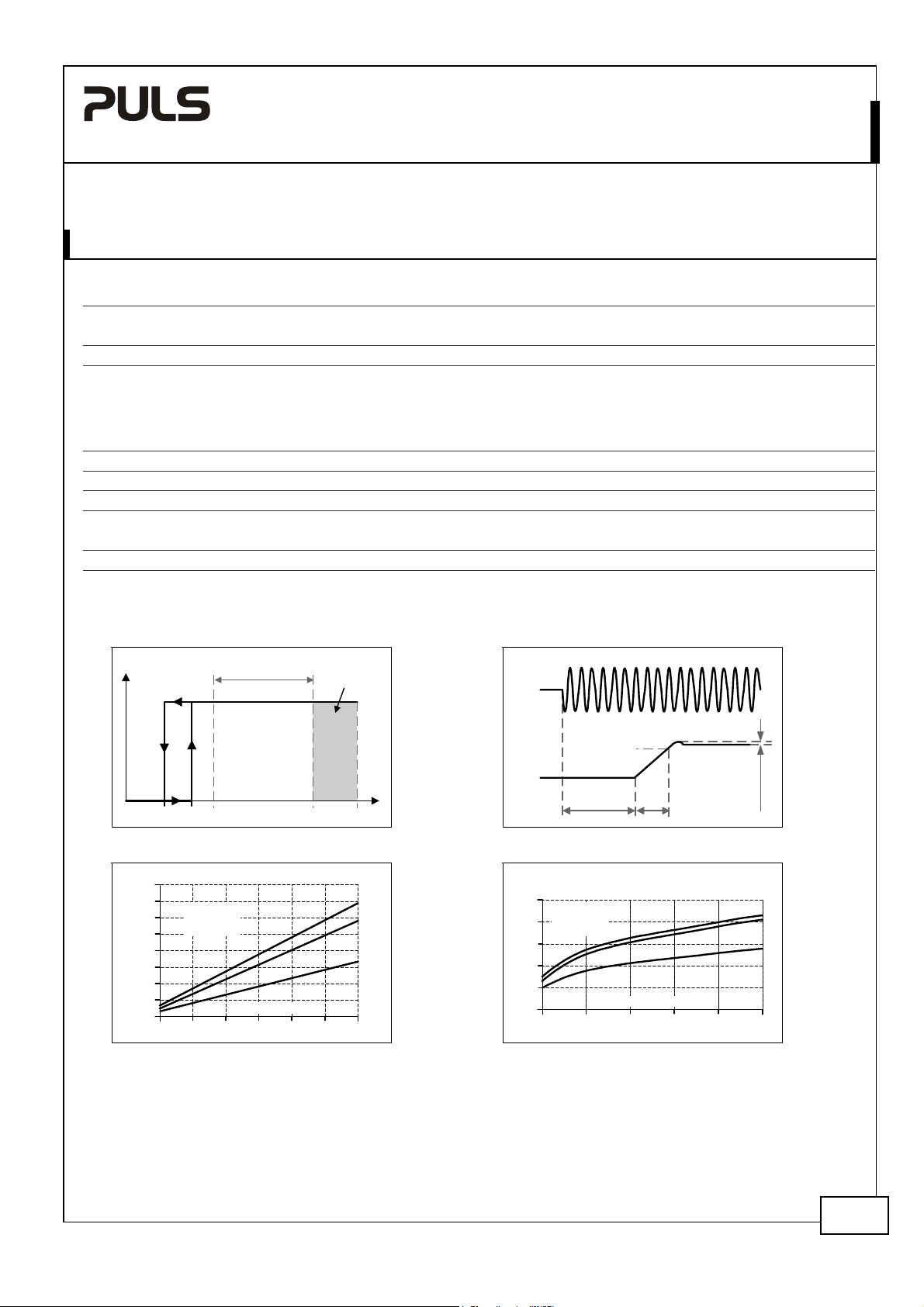
5. AC-INPUT
AC input
AC input range
264-300Vac < 0.5s
Input frequency nom. 50 – 60Hz ±6%
Turn-on voltage typ. 59Vac Steady-state value, see Fig. 5-1
Shut-down voltage typ. 54Vac Steady-state value, see Fig. 5-1
AC 100V AC 120V AC 230V
Input current (rms) typ. 0.34A 0.28A 0.17A At 5V, 3A see Fig. 5-3
Power factor *) typ. 0.52 0.51 0.44 At 5V, 3A see Fig. 5-1
Crest factor **) typ. 3.45 3.53 3.94 At 5V, 3A
Start-up delay typ. 630ms 630ms 630ms See Fig. 5-2
Rise time typ. 10ms 10ms 10ms At 5V, 3A, see Fig. 5-2
Turn-on overshoot
*) The power factor is the ratio of the true (or real) power to the apparent power in an AC circuit.
**) The crest factor is the mathematical ratio of the peak value to RMS value of the input current waveform.
Fig. 5-1 Input voltage range Fig. 5-2 Turn-on behavior, definitions
P
OUT
Rated
input range
nom. AC 100-240V Wide-range input, TN-, TT-, IT-Mains, see Fig. 5-1
85-264Vac Continuous operation
max. 100mV 100mV 100mV See Fig. 5-2
max.
500ms
Intput
Voltage
85V
59V
a) 100Vac
b) 120Vac
c) 230Vac
0.5
Turn-on
Output Current
1.5
1.0
V
IN
a
b
c
2.5
2.00
3.0A
Shut-down
54V 300Vac264V
Fig. 5-3 Input current vs. output load Fig. 5-4 Power Factor vs. output load
Input Current, typ.
0.4A
0.35
0.30
0.25
0.20
0.15
0.10
0.05
0
Output
Voltage
Power Factor, typ.
0.55
a) 100Vac
b) 120Vac
0.50
c) 230Vac
0.45
0.40
0.35
0.30
0.5 1.0
- 5%
Start-up
delay
Output Current
1.5 2.5
Rise
Time
2.0
Overshoot
a
b
c
3.0A
Dec. 2007 / Rev. 1.1 DS-ML15.051-EN
All parameters are specified at 5V, 3A, 230Vac, 25°C ambient and after a 5 minutes run-in time unless otherwise noted.
www.pulspower.com Phone +49 89 9278 0 Germany
3/19
Page 2
MiniLine
5V, 3A, SINGLE PHASE INPUT
ML15.051
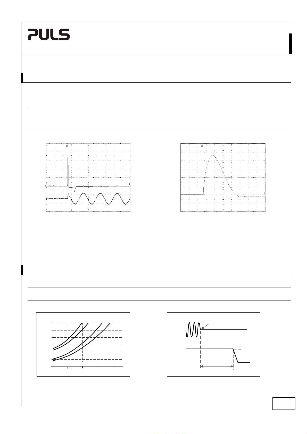
6. INPUT INRUSH CURRENT SURGE
A NTC limits the input inrush current after turn-on of the input voltage. The inrush current is input voltage and
ambient temperature dependent.
Inrush current max. 13A
typ. 11A
Inrush energy
typ. 0.1A2s 0.1A2s 0.4A2s 40°C ambient, cold start
Fig. 6-1 Input inrush current, typical behavior Fig. 6-2 Input inrush current, zoom into the first peak
Input Current
AC 100V AC 120V AC 230V
16A
peak
13A
peak
31A
peak
26A
peak
40°C ambient, cold start
peak
40°C ambient, cold start
peak
Input Current
Input Voltage
Input: 230Vac
Output: 5V, 3A
Ambient: 25°C
Upper curve: Input current 5A / DIV
Lower curve: Input voltage 500V / DIV
Time scale: 10ms / DIV
Input: 230Vac
Output: 5V, 3A
Ambient: 25°C
Input current curve: 5A / DIV, 500µs / DIV
Ipeak 23A
The charging current into EMI suppression capacitors is
disregarded in the first microseconds after switch-on.
7. HOLD-UP TIME
AC 100V AC 120V AC 230V
Hold-up Time typ. 61ms 93ms 355ms 5V, 1.5A, see
typ. 29.5ms 45ms 191ms 5V, 3A, see Fig. 7-1
Fig. 7-1 Hold-up time vs. input voltage Fig. 7-2 Shut-down behavior, definitions
Hold-up Time
150ms
125
100
75
50
25
0
85 120 155 190 230Vac
a b c d
a) 5V 1.5A typ.
b) 5V 1.5Amin.
c) 5V 3A typ.
d) 5V 3A min.
Input Voltage
Intput
Voltage
Output
Voltage
Hold-up Time
Note: At no load, the hold-up time can be up to several seconds. The green DC-ok lamp is also on during this time.
Fig. 7-1
Zero Transition
- 5%
Dec. 2007 / Rev. 1.1 DS-ML15.051-EN
All parameters are specified at 5V, 3A, 230Vac, 25°C ambient and after a 5 minutes run-in time unless otherwise noted.
www.pulspower.com Phone +49 89 9278 0 Germany
4/19
Page 3

MiniLine
5V, 3A, SINGLE PHASE INPUT
ML15.051
8. DC-INPUT
DC input nom. DC 110-290V -25%/+30%
DC input range min. 85-375Vdc Continuous operation
DC input current typ. 0.16A / 0.057A 110Vdc / 300Vdc, at 5V and 3A output load
Turn-on voltage typ. 80Vdc Steady state value
Shut-down voltage typ. 60Vdc Steady state value
Instructions for DC use:
a) Use a battery or similar DC source.
b) Connect +pole to L and – pole to N.
c) In case the – pole of the battery is not connected to earth, use an appropriate fuse to protect the N terminal.
Fig. 8-1 Wiring for DC Input
Battery
+
Fuse
-
Power Supply
AC
internal
fused
L
N
FE
DC
+
Load
-
Dec. 2007 / Rev. 1.1 DS-ML15.051-EN
All parameters are specified at 5V, 3A, 230Vac, 25°C ambient and after a 5 minutes run-in time unless otherwise noted.
www.pulspower.com Phone +49 89 9278 0 Germany
5/19
Page 4
MiniLine
5V, 3A, SINGLE PHASE INPUT
ML15.051
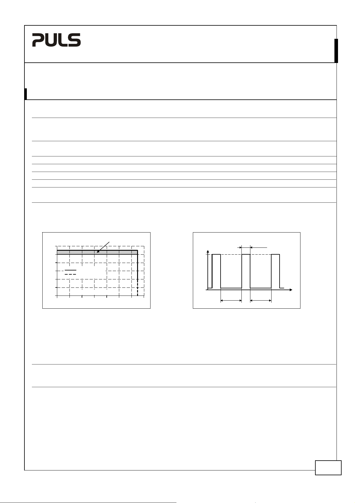
9. OUTPUT
Output voltage
Adjustment range
max. 6V At clockwise end position of potentiometer
Factory setting
Line regulation
Load regulation max.
Ripple and noise voltage
Output capacitance typ.
Output current nom. 3A See Fig. 9-1 for typical values
Output power nom. 15W
Short-circuit current min. Hiccup mode See Fig. 9-2
max. Hiccup mode See Fig. 9-2
Fig. 9-1 Output voltage vs. output current, typ.
nom. 5V
min. 5.0-5.5V Guaranteed
max.
max.
5.1V
10mV
100mV
50mVpp
4800µF
±0.2%, at full load, cold unit
85 to 264Vac
Static value, 0A Æ 3A Æ 0A
20Hz to 20MHz, 50Ohm
Fig. 9-2 Hiccup mode, Output current at
shorted output, 230V typ.
Output Voltage
6V
5
4
3
2
1
0
Continuous
Hiccup Mode
Output Current
0
Adjustment
Range
Output
Current
3.3A
45ms
0
235ms 235ms
3.5A2.51.50.5 2.01.0 3.0
t
Peak current capability (up to several ms)
The power supply can deliver a peak current which is higher than the specified short term current. This helps to start
current demanding loads or to safely operate subsequent circuit breakers.
The extra current is supplied by the output capacitors inside the power supply. During this event, the capacitors will
be discharged and cause a voltage dip on the output. Detailed curves can be found in chapter 25.1
Peak current voltage dips typ. from 5V to 2.4V At 6A for 50ms, resistive load
typ. from 5V to 1.0V
typ. from 5V to 0.8V
At 15A for 2ms, resistive load
At 15A for 5ms, resistive load
Dec. 2007 / Rev. 1.1 DS-ML15.051-EN
All parameters are specified at 5V, 3A, 230Vac, 25°C ambient and after a 5 minutes run-in time unless otherwise noted.
www.pulspower.com Phone +49 89 9278 0 Germany
6/19
Page 5

A
c
c
MiniLine
5V, 3A, SINGLE PHASE INPUT
ML15.051
10. EFFICIENCY AND POWER LOSSES
AC 100V AC 120V AC 230V
Efficiency typ. 75.8% 76.8% 77.2% 5V, 3A (full load)
Power losses typ. 0.2W 0.3W 0.6W At no load
typ. 2.3W 2.3W 2.4W 5V, 1.5A (half load)
typ. 4.9W 4.6W 4.5W 5V, 3A (full load)
Fig. 10-1 Efficiency vs. output current at 5V Fig. 10-2 Losses vs. output current at 5V
Power Losses
5W
a) 100Vac
b) 120Vac
4
c) 230Vac
3
2
1
c
b
a
0
0
0.5 3.0
1.0 1.5 2.0
Efficiency
78%
77
76
75
74
73
72
71
70
0
Output Current
0.5 2.0
a) 100Vac
b) 120Vac
c) 230Vac
c
b
a
3.0A1.0 1.5 2.5
Fig. 10-3 Efficiency vs. input voltage
Efficiency
78%
77
76
75
74
73
72
85 120 155 190 225 260
at 5V and 3A
Input Voltage
Va
Fig. 10-4 Losses vs. input voltage
Power Losses
5W
4.75
4.50
4.25
4.00
3.75
85 120 155 190 225 260
at 5V and 3A
Input Voltage
Output Current
2.5
a
b
c
Va
Dec. 2007 / Rev. 1.1 DS-ML15.051-EN
All parameters are specified at 5V, 3A, 230Vac, 25°C ambient and after a 5 minutes run-in time unless otherwise noted.
www.pulspower.com Phone +49 89 9278 0 Germany
7/19
 Loading...