

Page 1
MiniLine
5V, 3A, SINGLE PHASE INPUT
ML15.051
25. APPLICATION NOTES
25.1. PEAK CURRENT CAPABILITY
Solenoids, contactors and pneumatic modules often have a steady state (sealed) coil and a pick-up coil. The inrush
current demand of the pick-up coil is several times higher than the steady state current and usually exceeds the
nominal output current. The same situation applies, when starting a capacitive load.
Branch circuits are often protected with circuit breakers or fuses. In case of a short or an overload in the branch
circuit, the protective device (fuse, circuit breaker) needs a certain amount of over-current to trip or to blow. The
peak current capability ensures the safe operation of subsequent circuit breakers.
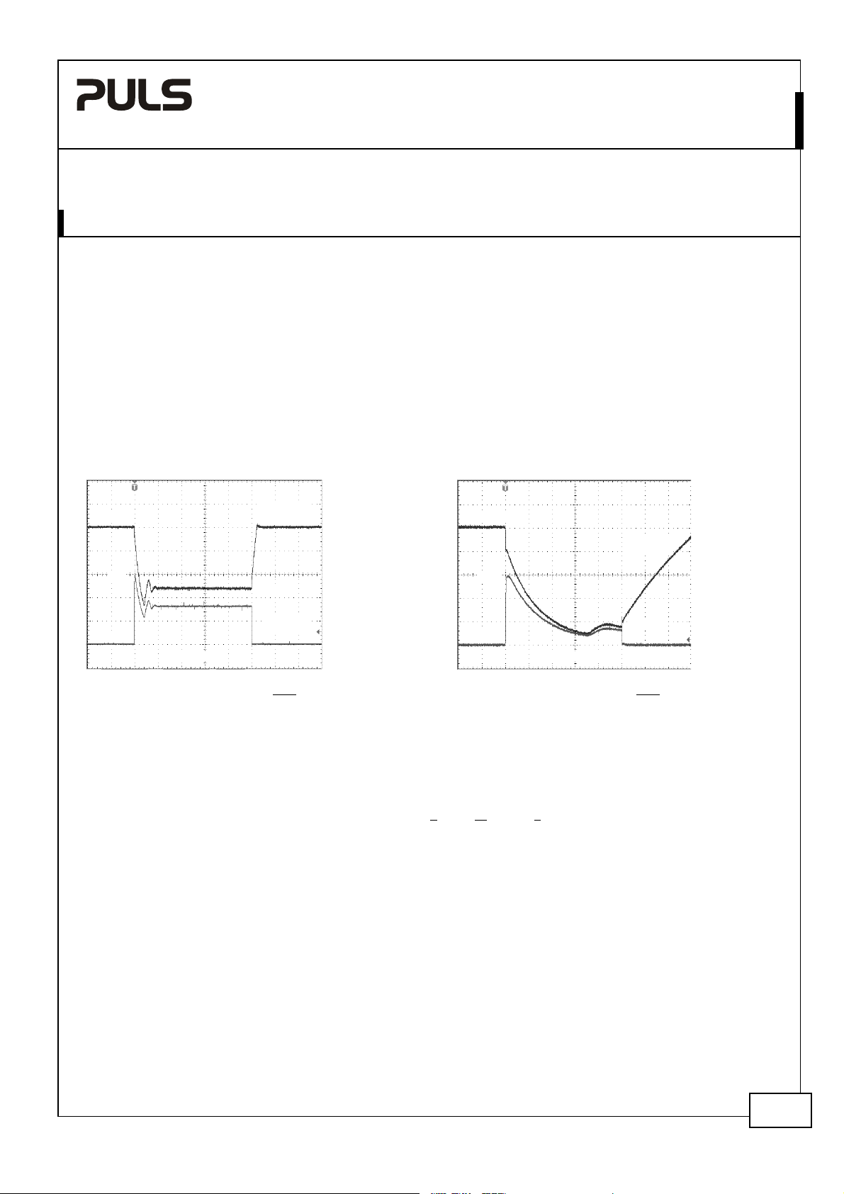
Assuming the input voltage is turned on before such an event, the built-in large sized output capacitors inside the
power supply can deliver extra current. Discharging this capacitor causes a voltage dip on the output. The following
two examples show typical voltage dips:
Fig. 25-1 Peak load 6A for 50ms, typ. Fig. 25-2 Peak load 15A for 5ms, typ.
5.1V
Output
Voltage
5.1V
Output
Voltage
6A
2.4V
Output
0A
10ms/DIV
Peak load 6A (resistive) for 50ms
Output voltage dips from 5V to 2.4V.
Current
15A
0A
1ms/DIV
Peak load 15A (resistive) for 5ms
Output voltage dips from 5V to 0.8V.
0.8V
Output
Current
25.2. BACK-FEEDING LOADS
Loads such as decelerating motors and inductors can feed voltage back to the power supply. This feature is also called
return voltage immunity or resistance against Back- E.M.F. (E
The maximum allowed feed back voltage is 6.3Vdc. The absorbing energy can be calculated according to the built-in
large sized output capacitor which is specified in chapter 9.
This power supply is resistant and does not show malfunctioning when a load feeds back voltage to the power
supply. It does not matter, whether the power supply is on or off. However, please note that the output voltage can
dip to zero for approximatelly 200ms if the back-feed voltage is removed.
lectro Magnetic Force).
25.3. INDUCTIVE AND CAPACITIVE LOADS
The unit is designed to supply unlimited inductive loads. The max. capacitive load depend on the steady state output
current. At 3A output current, the output capacity should not be larger than 10 000µF at 1.5A output not larger than
25 000µF. In case of larger capacitors, the unit can show start-up attempts or start-up problems.
Dec. 2007 / Rev. 1.1 DS-ML15.051-EN
All parameters are specified at 5V, 3A, 230Vac, 25°C ambient and after a 5 minutes run-in time unless otherwise noted.
www.pulspower.com Phone +49 89 9278 0 Germany
15/19
Page 2
MiniLine
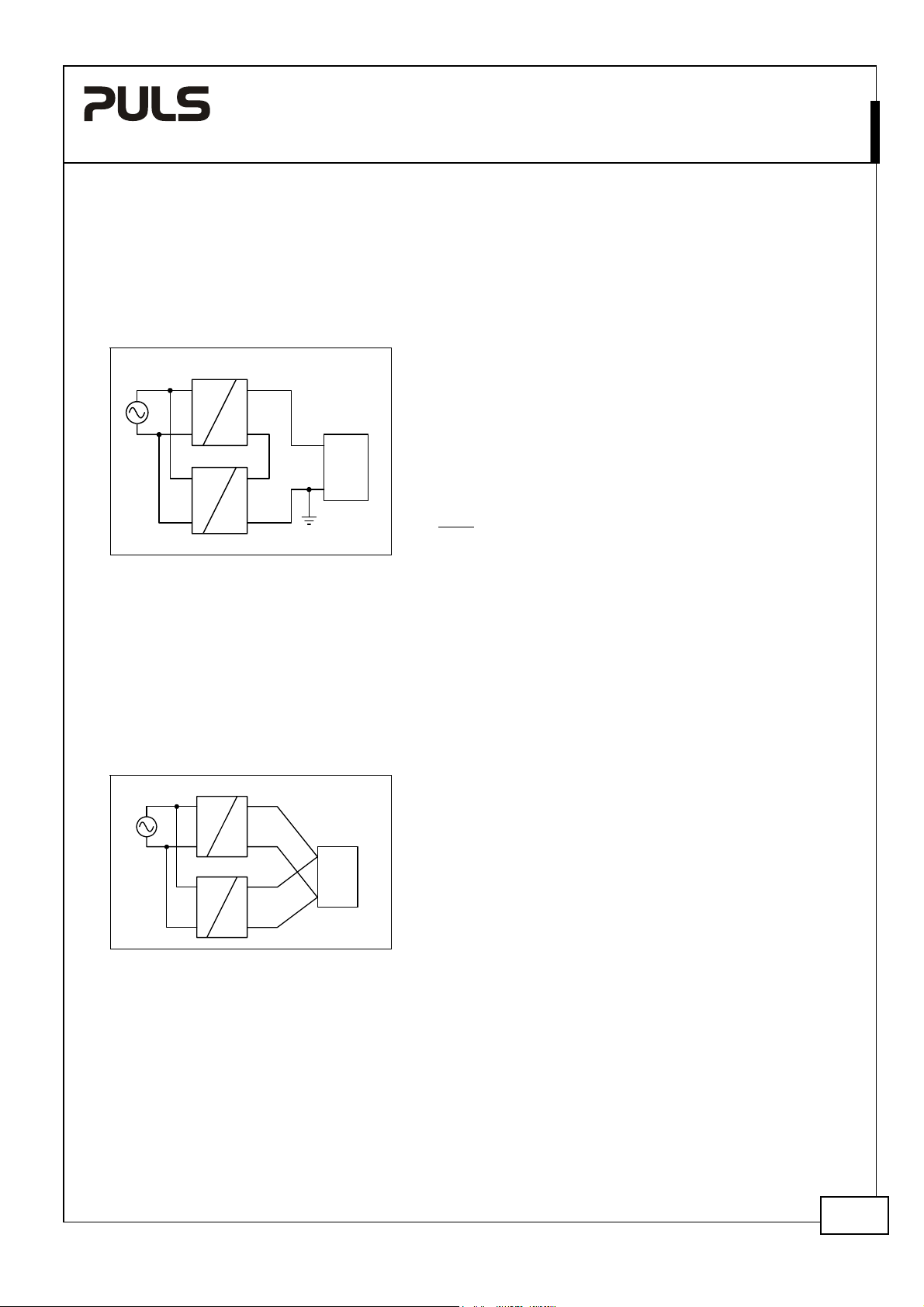
25.4. SERIES OPERATION
The power supply can be put in series to increase the output voltage.
Fig. 25-3 Schematic for series operation
Unit A
AC
Unit B
AC
DC
DC
+
-
+
-
+
Load
-
Earth
Instructions for use in series:
a) It is possible to connect as many units in series as needed,
providing the sum of the output voltage does not exceed
150Vdc.
b) Voltages with a potential above 60Vdc are not SELV any
more and can be dangerous. Such voltages must be installed
with a protection against touching.
c) For serial operation use power supplies of the same type.
d) Earthing of the output is required when the sum of the
output voltage is above 60Vdc.
Note: Avoid return voltage (e.g. from a decelerating motor or
battery) which is applied to the output terminals.
ML15.051
5V, 3A, SINGLE PHASE INPUT
25.5. PARALLEL USE TO INCREASE OUTPUT POWER
Several power supplies can be paralleled to increase the output power. The ML15.051 has no feature included which
balances the load current between the power supplies. Usually the power supply with the higher adjusted output
voltage draws current until it goes into current limitation. This means no harm to this power supply as long as the
ambient temperature stays below 50°C.
Fig. 25-4 Schematic for parallel operation
Unit A
AC
AC
Unit B
DC
DC
+
+
Load
+
-
-
Instructions for parallel use:
a) Use only power supplies from the same series (ML-Series).
b) Adjust the output voltages of all power supplies to
approximately the same value (±50mV).
c) A fuse (or diode) on the output is only required if more than
three units are connected in parallel.
d) Ensure that the ambient temperature of the power supply
does not exceed 50°C.
Dec. 2007 / Rev. 1.1 DS-ML15.051-EN
All parameters are specified at 5V, 3A, 230Vac, 25°C ambient and after a 5 minutes run-in time unless otherwise noted.
www.pulspower.com Phone +49 89 9278 0 Germany
16/19
Page 3

MiniLine
5V, 3A, SINGLE PHASE INPUT
ML15.051
25.6. PARALLEL USE FOR REDUNDANCY
Power supplies can be paralleled for redundancy to gain a higher system reliability. Redundant systems require a
certain amount of extra power to support the load in case one power supply unit fails. The simplest way is to put two
MiniLine power supplies in parallel. This is called a 1+1 redundancy. In case one power supply unit fails, the other one
is automatically able to support the load current without any interruption. Redundant systems for a higher power
demand are usually built in a N+1 method. E.g. Five power supplies, each rated for 3A are paralleled to build a 12A
redundant system. If one unit fails, the 12A can still be drawn.
25.7. EXTERNAL INPUT PROTECTION
The unit is tested and approved for branch circuits up to 15A (UL) or 16A (IEC). External protection is only required if
the supplying branch has an ampacity greater than this. In some countries local regulations might apply so check local
codes and requirements.
If an external protective device is utilized, a minimum value is required to avoid undesired tripping of the fuse.
B-Characteristic C-Characteristic
Ampacity max.
min.
15A (UL), 16A (IEC) 15A (UL), 16A (IEC)
10A 6A
25.8. FUNCTIONAL EARTH TERMINAL
From a safety standpoint, the unit is designed according to the requirements for Protection Class 2 which does not
require an earth connection. However, connecting the Functional Earth terminal can be beneficial to gain a high EMI
immunity.
Symmetrical spikes or fast transients on the input side can be conducted directly to earth by the built-in filter
capacitors. The magnitude of such spikes or fast transients on the output side caused by the input are much smaller
compared to not connecting the FE terminal to ground.
Therefore, we recommend to connect the FE terminal too ground.
Fig. 25-5 Functional earth terminal connected to
earth
Surge
Power Supply
L
N
FE
+
X
-
Y
Fig. 25-6 Functional earth terminal not connected to
Surge
Power Supply
L
N
earth
X
Spike
24V
+
-
Dec. 2007 / Rev. 1.1 DS-ML15.051-EN
All parameters are specified at 5V, 3A, 230Vac, 25°C ambient and after a 5 minutes run-in time unless otherwise noted.
www.pulspower.com Phone +49 89 9278 0 Germany
17/19
Page 4

MiniLine
25.9. OPERATION ON TWO PHASES
The power supply can be used on two phases of a three-phase-system
Instructions for two phase operation:
a) A phase to phase connection is allowed as long as the supplying voltage is below 240V
b) Use a fuse or a circuit breaker to protect the N input. The N input is internally not protected and is in this
case connected to a hot wire. Appropriate fuses or circuit breakers are specified in section 25.7 “External
Input Protection”.
Fig. 25-7 Schematic for two phase operation
Power Supply
L
Fuse
N
FE
AC
internal
fuse
DC
L3
L1
max.
+10%
240V
L2
ML15.051
5V, 3A, SINGLE PHASE INPUT
+10%
.
25.10. USE IN A TIGHTLY SEALED ENCLOSURE
When the power supply is installed in a tightly sealed enclosure, the temperature inside the enclosure will be higher
than the outside. The inside temperature defines the ambient temperature for the power supply.
Results from such an installation:
Power supply is placed in the middle of the box, no other heat producing equipment inside the box
Enclosure: Rittal Type IP66 Box PK 9510 100, plastic, 130x130x75mm
Input: 230Vac
Load: 5V, 3A
Temperature inside the box: 38.2°C (in the middle of the right side of the power supply with a distance of 1cm)
Temperature outside the box: 26.0°C
Temperature rise: 12.2K
Load: 5V, 2.4A
Temperature inside the box: 35.3°C (in the middle of the right side of the power supply with a distance of 1cm)
Temperature outside the box: 25.6°C
Temperature rise: 9.7K
; load is placed outside the box
; (=80%) load is placed outside the box
Dec. 2007 / Rev. 1.1 DS-ML15.051-EN
All parameters are specified at 5V, 3A, 230Vac, 25°C ambient and after a 5 minutes run-in time unless otherwise noted.
www.pulspower.com Phone +49 89 9278 0 Germany
18/19
Page 5

C
C
C
C
C
MiniLine
5V, 3A, SINGLE PHASE INPUT
ML15.051
25.11. MOUNTING ORIENTATIONS
Mounting orientations other than input terminals on the bottom and output on the top requires a reduction in
continuous output power or a limitation in the maximum allowed ambient temperature. The amount of reduction
influences the lifetime expectancy of the power supply. Therefore, two different derating curves for continuous
operation can be found below:
Curve A1 Recommended output power.
Curve A2 Max allowed output power (results approx. in half the lifetime expectancy of A1).
Fig. 25-8
Mounting
Orientation A
Standard
Orientation
Fig. 25-9
Mounting
Orientation B
(Upside down)
OUTPUT
Power
Supply
INPUT
INPUT
Supply
Power
OUTPUT
Fig. 25-10
Mounting
Orientation C
(Table-top
mounting)
Fig. 25-11
Mounting
Orientation D
(Horizontal cw)
Supply
INPUT
OUTPUT
Power
Fig. 25-12
Mounting
Orientation E
(Horizontal ccw)
OUTPUT
Power
INPUT
Supply
Output Power
15W
12
9
6
3
0
Ambient Temperature
10 20 30 40
Output Power
15W
12
9
6
3
0
Ambient Temperature
10 20 30 40
Output Power
15W
12
9
6
3
0
Ambient Temperature
10 20 30 40
Output Power
15W
12
9
6
3
0
Ambient Temperature
10 20 30 40
Output Power
15W
12
9
6
3
0
Ambient Temperature
10 20 30 40
50
50
50
50
50
A
1
60°
A
2
A
1
60°
A
2
A
1
60°
A
2
A
1
60°
A
2
A
1
60°
Dec. 2007 / Rev. 1.1 DS-ML15.051-EN
All parameters are specified at 5V, 3A, 230Vac, 25°C ambient and after a 5 minutes run-in time unless otherwise noted.
www.pulspower.com Phone +49 89 9278 0 Germany
19/19
 Loading...