

Page 1
CD–Series
DC/DC Converter; 24V, 5A
CD5.242
5. INPUT VOLTAGE
Input
Input voltage range
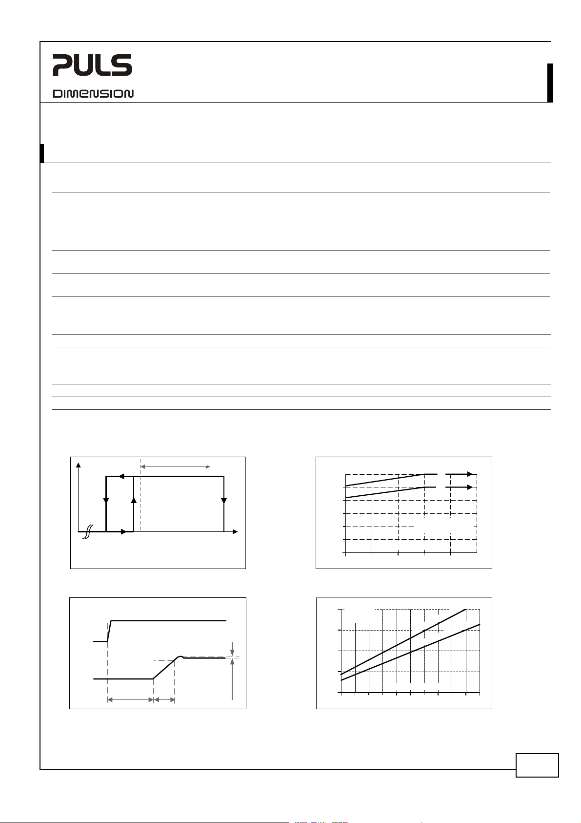
typ. 30.5-36.0Vdc Max. 60 seconds or with de-rating, see Fig. 5-2
Allowed voltage between input
and earth (ground)
Allowed input ripple voltage
Turn-on voltage typ. 34.5Vdc Steady-state value, see Fig. 5-1
Shut-down voltage typ. 30.5Vdc Steady-state value, see Fig. 5-1
Input current
Start-up delay typ.
Rise time typ. 80ms 0mF, 24V, 5A, constant current load, see Fig. 5-3
Turn-on overshoot
Input capacitance typ.
External capacitors on the input voltage bus are allowed without any limitations.
Fig. 5-1 Input voltage range
P
OUT
Shut-down
30.5Vdc
Rated input range
Turn-on
35.0Vdc
36.0Vdc
Fig. 5-3 Turn-on behavior, definitions Fig. 5-4 Input current vs. output load
Intput
Voltage
Output
Voltage
- 5%
Start-up
delay
Rise
Time
nom. DC 48V
nom. 36.0-60.0Vdc Continuous operation
max. 63.0Vdc Absolute maximum continuous input voltage with no
damage to the DC/DC converter. Please note that the unit
can switch off above 60Vdc
max. 60Vdc or
42.4Vac
max. 5Vpp 47Hz-40kHz, the momentary input voltage must always be
within the specified limits.
typ. 63.5Vdc Steady-state value, see Fig. 5-1
typ. 2.75A At 48Vdc input and output 24V, 5A, see Fig. 5-4
670ms
0mF, 24V, 5A, constant current load, see Fig. 5-3
typ. 150ms 5mF, 24V, 5A, constant current load, see Fig. 5-3
60.0Vdc
500mV
800µF
V
IN
63.5Vdc
Overshoot
See Fig. 5-3
Fig. 5-2 Allowable output current below 36V
Output Current
6A
5
4
3
2
1
0
30 32 34 36 40Vdc
Input
4A
Current,
typ.
3
2
1
0
1
1.5 2 3
input voltage
(a) Ambient < 45°C
(b) Ambient < 60°C
Input Voltage
Output Current
3.5
2.5
u
p
n
I
n
I
4
t
p
4.5
)
a
(
)
b
(
38
c
d
V
6
3
:
V
8
4
:
t
u
5
d
5.5
c
6A
max.
July 08 / Rev. 1.2 DS-CD5.242-EN / All parameters are specified at 24V, 5A and 48Vdc input at 25°C ambient unless otherwise noted.
www.pulspower.com Phone +49 89 9278 0 Germany
3/21
Page 2
CD–Series
DC/DC Converter; 24V, 5A
CD5.242
6. SOFT-START AND INPUT INRUSH CURRENT SURGE
Inrush current limitation
An active inrush limitation circuit (inrush limiting resistor which is bypassed by a relay contact) limits the input inrush
current after turn-on of the input voltage.
The charging current into EMI suppression capacitors is disregarded in the first microseconds after switch-on.
Inrush current
max. 0.8A
typ. 0.6A
Inrush energy
typ. negligible -25°C to +70°C
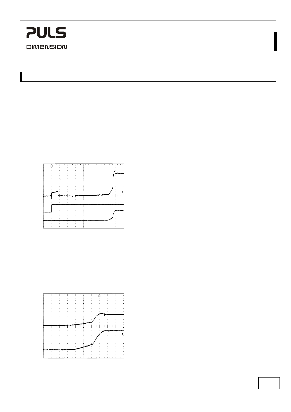
Fig. 6-1 Input inrush current, typical behavior
Input Current
Input Voltage
Input 48Vdc
-25°C to +70°C
peak
-25°C to +70°C
peak
Input: 48Vdc
Output: 24Vdc, 5A, constant current load
Ambient: 25°C
Upper curve: Input current 1A / DIV
Middle curve: Input voltage 50V / DIV
Lower curve: Output voltage 20V / DIV
Time scale: 100ms / DIV
Output Voltage
Soft-start function:
After the DC/DC converter is turned on, the internal output current rises slowly to its nominal value. This method
charges the output capacitors (internal and external capacitors) slowly and avoids high input currents during turn-on.
High input currents can produce a high voltage drop on the input wiring (especially with long and thin cables) which
reduces the terminal voltage on the DC/DC converter. If the terminal voltage is below the shut-down voltage, the
DC/DC converter will turn-off and will make a new start-up attempt. This effect is avoided with the integrated softstart function. Please note, that this function increases the rise time of the output voltage by a small amount.
Fig. 6-2 Soft-start behavior
Input: 48Vdc
Output: 24Vdc, 5A, constant current load
Ambient: 25°C
No additional external capacitors
Input Current
Upper curve: Input current 2A / DIV
Lower curve: Output voltage 10V / DIV
Time scale: 20ms / DIV
Output Voltage
July 08 / Rev. 1.2 DS-CD5.242-EN / All parameters are specified at 24V, 5A and 48Vdc input at 25°C ambient unless otherwise noted.
www.pulspower.com Phone +49 89 9278 0 Germany
4/21
Page 3

A
c
CD–Series
DC/DC Converter; 24V, 5A
CD5.242
7. OUTPUT
Output voltage
Adjustment range
max. 30V At clockwise end position of potentiometer
Factory setting
Line regulation
Load regulation max. 100mV Static value, 0A Æ 5A Æ 0A
Ripple and noise voltage
Output capacitance typ.
Output current nom. 6A At 24V, ambient < 45°C, see Fig. 7-1
nom. 5A
Output power nom. 144W Ambient < 45°C
nom. 120W
Short-circuit current
max. 10A Load impedance 200mOhm, see Fig. 7-1
Fig. 7-1 Output voltage vs. output current,
typ. (48Vdc input voltage)
nom. 24V
min. 23-28V Guaranteed
max.
max.
24.1V
25mV
50mVpp
2200µF
±0.2%, at full load, cold unit
Input variations between 36 to 60Vdc
20Hz to 20MHz, 50Ohm
At 24V, ambient < 60°C, see
Fig. 7-1
nom. 5.1A At 28V, ambient < 45°C, see Fig. 7-1
nom. 4.3A
At 28V, ambient < 60°C, see
Fig. 7-1
Ambient < 60°C
min. 7A Load impedance 200mOhm, see Fig. 7-1
Fig. 7-2 Current limitation vs. input voltage,
typ. (23V constant voltage load)
Output Voltage
28V
24
20
16
12
8
4
0
Adjustment
Range
Output Current
048
1062
12
Output Current
7.0A
6.9
6.8
6.7
6.6
6.5
6.4
6.3
6.2
30 42 54
Input Voltage
4836
60Vd
Peak current capability (up to several ms)
The DC/DC converter can deliver a peak current which is higher than the specified short term current. This helps to
start current demanding loads or to safely operate subsequent circuit breakers.
The extra current is supplied by the output capacitors inside the DC/DC converter. During this event, the capacitors
will be discharged and cause a voltage dip on the output. Detailed curves can be found in chapter 25.1.
Peak current voltage dips typ. from 24V to 17.1V At 10A for 50ms, resistive load
typ. from 24V to 15V
typ. from 24V to 11V
At 20A for 2ms, resistive load
At 20A for 5ms, resistive load
July 08 / Rev. 1.2 DS-CD5.242-EN / All parameters are specified at 24V, 5A and 48Vdc input at 25°C ambient unless otherwise noted.
www.pulspower.com Phone +49 89 9278 0 Germany
5/21
Page 4

CD–Series
DC/DC Converter; 24V, 5A
CD5.242
8. HOLD-UP TIME
The input side of the DC/DC converter is equipped with a bulk capacitor which keeps the output voltage alive for a
certain period of time when the input voltage dips or is removed. The bulk capacitor can be discharged by loading
the DC/DC converter on the output side or through a load which is parallel to the input. There is no protection in the
DC/DC converter which prevents current from flowing back to the input terminals. If prevention is needed, an
external diode should be used.
Input 48Vdc
Hold-up Time typ. 10.5ms Input 48Vdc, Output: 24Vdc, 2.5A, see
typ. 5.6ms Input 48Vdc, Output: 24Vdc, 5A, see Fig. 8-1
Fig. 8-1 Hold-up time vs. input voltage
Hold-up Time
12ms
10
8
6
4
2
0
Input Voltage
36 40 44 48 56Vdc
)
(
a
(
b
)
)
(
c
)
(
d
(a) 24V, 2.5A, typ.
(b) 24V, 2.5A, min.
(c) 24V, 5A, typ.
(d) 24V, 5A, min.
52
Fig. 8-2 Shut-down test setup Fig. 8-3 Shut-down behavior, definitions
DC/DC
Converter
S1
Input
Output
CD5
+
+
Load
-
-
DC
Source
+
-
Intput
Voltage
Output
Voltage
Fig. 8-1
S1 opens
- 5%
Hold-up Time
Note: At no load, the hold-up time can be up to several seconds. The green DC-ok lamp is also on during this time.
July 08 / Rev. 1.2 DS-CD5.242-EN / All parameters are specified at 24V, 5A and 48Vdc input at 25°C ambient unless otherwise noted.
www.pulspower.com Phone +49 89 9278 0 Germany
6/21
Page 5

A
A
c
c
CD–Series
DC/DC Converter; 24V, 5A
9. EFFICIENCY AND POWER LOSSES
Input 48Vdc
Efficiency typ. 90.3% 5A, 24V
Power losses typ. 0.9W At no output load
typ. 6.9W 2.5A, 24V
typ. 12.9W 5A, 24V
typ. 16.4W 6A, 24V
Fig. 9-1 Efficiency vs. output current at 24V
output voltage and 48V input voltage
Efficiency
91%
90
89
88
87
86
85
1
Output Current
2453
6
Fig. 9-2 Losses vs. output current at 24V
output voltage and 48V input voltage
Power Losses
18W
15
12
9
6
3
0
012 456
Fig. 9-3 Efficiency vs. input voltage, 24V, 5A
Efficiency
91%
90.5
90.0
89.5
89.0
88.5
88.0
36 40 44 52 56 60
output
Input Voltage
48
Vd
Fig. 9-4 Losses vs. input voltage, 24V, 5A
Power Losses
18W
15
12
9
6
3
0
36 40 48 52 56 60
Output Current
3
output
Input Voltage
44
CD5.242
Vd
July 08 / Rev. 1.2 DS-CD5.242-EN / All parameters are specified at 24V, 5A and 48Vdc input at 25°C ambient unless otherwise noted.
www.pulspower.com Phone +49 89 9278 0 Germany
7/21
 Loading...