

Page 1
CD5.241-L1
CD-Series
DC/DC Converter 24V, 3.8A
22. APPLICATION NOTES
22.1. PEAK CURRENT CAPABILITY
Solenoids, contactors and pneumatic modules often have a steady state coil and a pick-up coil. The inrush current
demand of the pick-up coil is several times higher than the steady-state current and usually exceeds the nominal
output current (including the PowerBoost). The same situation applies, when starting a capacitive load.
Branch circuits are often protected with circuit breakers or fuses. In case of a short or an overload in the branch circuit,
the fuse needs a certain amount of over-current to trip or to blow. The peak current capability ensures the safe
operation of subsequent circuit breakers.
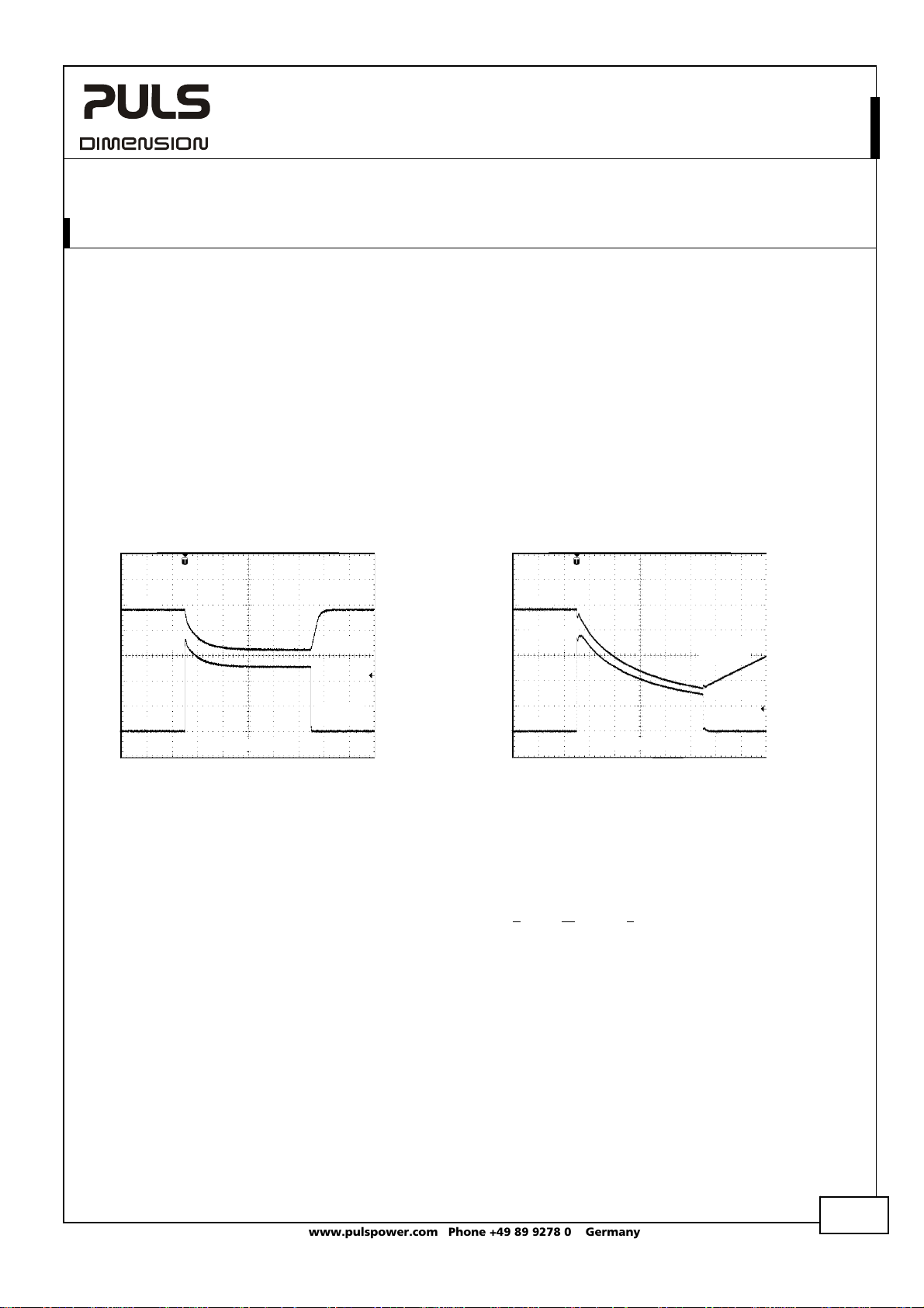
Assuming the input voltage is turned on before such an event, the built-in large sized output capacitors inside the
DC/DC converter can deliver extra current. Discharging this capacitor causes a voltage dip on the output. The following
two examples show typical voltage dips:
Fig. 22-1 Peak loading with 2x the nominal
24V
current for 50ms, typ.
Output
Voltage
Fig. 22-2 Peak loading with 5x the nominal
current for 5ms, typ.
24V
7.6A
0A
10ms/DIV
Peak load 7.6A (resistive load) for 50ms
Output voltage dips from 24V to 16V.
16V
Output
Current
19A
0A
1ms/DIV
Peak load 19A (resistive load) for 5ms
Output voltage dips from 24V to 8.5V.
Output
Voltage
8.5V
Output
Current
22.2. BACK-FEEDING LOADS
Loads such as decelerating motors and inductors can feed voltage back to the DC/DC converter. This feature is also
called return voltage immunity or resistance against Back- E.M.F. (E
This DC/DC converter is resistant and does not show malfunctioning when a load feeds back voltage to the DC/DC
converter. It does not matter, whether the DC/DC converter is on or off.
The maximum allowed feed-back-voltage is 30Vdc. The absorbing energy can be calculated according to the built-in
large sized output capacitance which is specified in chapter 5.
lectro Magnetic Force).
22.3. INDUCTIVE AND CAPACITIVE LOADS
The unit is designed to supply any kind of loads, including unlimited capacitive and inductive loads.
Oct 2009 / Rev. 1.0 DS-CD5.241-L1-EN
All parameters are specified at 24V, 3.8A, 24Vdc input voltage, 25°C ambient and after a 5 minutes run-in time unless otherwise noted.
www.pulspower.com Phone +49 89 9278 0 Germany
17/20
Page 2
CD5.241-L1
CD-Series
DC/DC Converter 24V, 3.8A
22.4. EXTERNAL INPUT PROTECTION
The unit is tested and approved for branch circuits up to 50A. An external protection is only required, if the supplying
branch has an ampacity greater than this. Check also local codes and local requirements. In some countries local
regulations might apply.
If an external fuse is necessary or utilized, minimum requirements need to be considered to avoid nuisance tripping of
the circuit breaker. A minimum value of 10A B- or 8A C-Characteristic breaker should be used.
22.5. REQUIREMENTS FOR THE SUPPLYING SOURCE
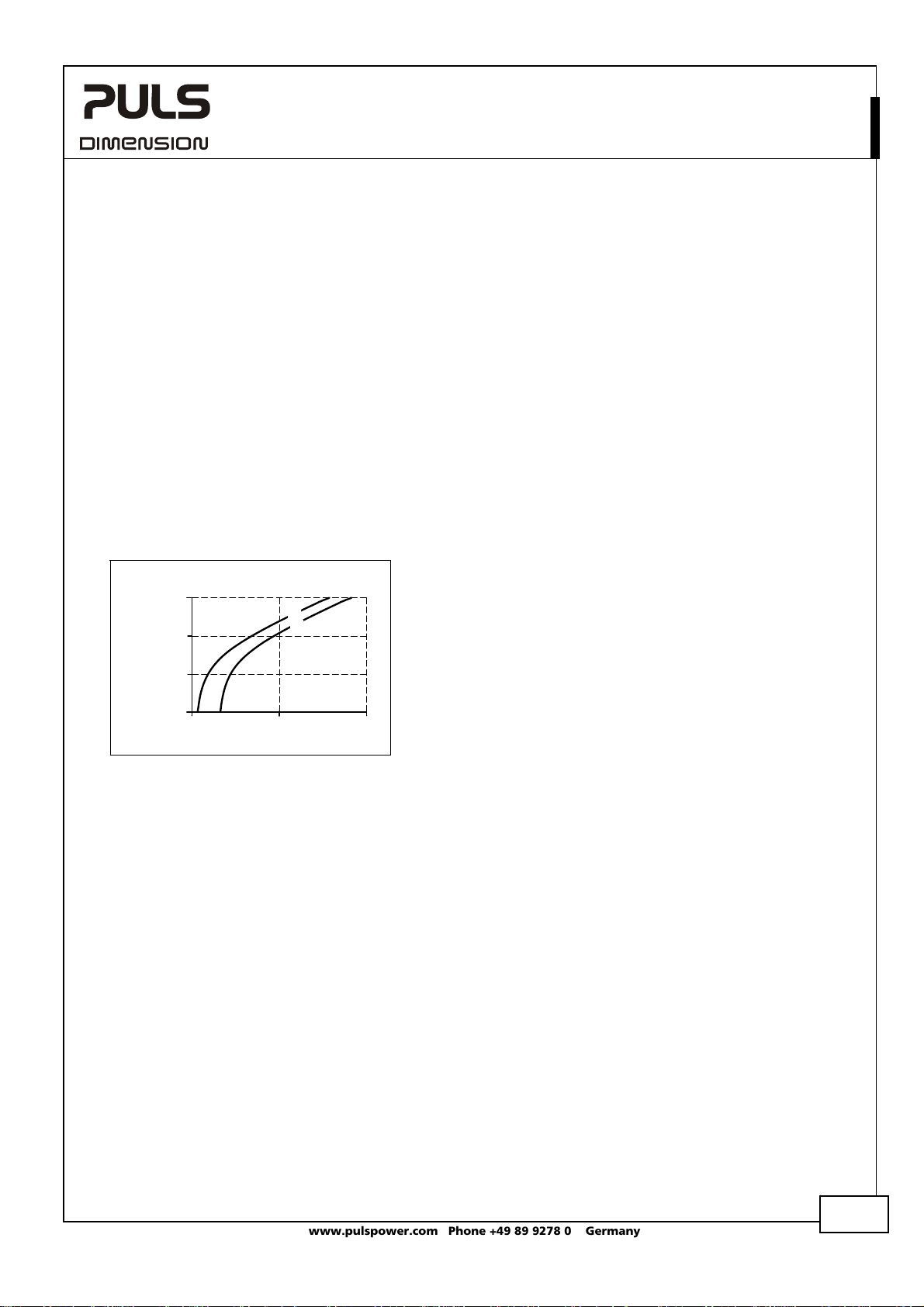
In certain circumstances, the input filter of the DC/DC converter can show a resonant effect which is caused by the
supplying network. Especially when additional external input filters are utilized, a superimposed AC voltage can be
generated on the input terminals of the DC/DC converter which might cause a malfunction of the unit. Therefore,
additional input filters are not recommended. To avoid the resonant effects, the minimal resistance of the supplying
network which depends on the inductance of the input network, shall be above the boundary curve in Fig. 22-3.
Fig. 22-3 External input filter requirements to
Resistance of the
supplying network
100 mOhm
10 mOhm
1 mOhm
avoid filter instabilities
1 Ohm
0.1mH 1mH 10mH
Inductance of the supplying network
a
)
(
b
(
)
(a) max.
(b) typ.
22.6. PARALLEL USE TO INCREASE OUTPUT POWER
This DC/DC-converter is designed to meet the NEC Class 2 requirements. Do not use in parallel to increase the output
current. This would increase the output current and violates the NEC Class 2 limitations. Use CD5.241 or CD5.241-S1.
22.7. PARALLEL USE FOR REDUNDANCY
This DC/DC-converter is designed to meet the NEC Class 2 requirements. Do not use in parallel for redundancy. This
would increase the output current and violates the NEC Class 2 limitations. Use CD5.241 or CD5.241-S1.
Oct 2009 / Rev. 1.0 DS-CD5.241-L1-EN
All parameters are specified at 24V, 3.8A, 24Vdc input voltage, 25°C ambient and after a 5 minutes run-in time unless otherwise noted.
www.pulspower.com Phone +49 89 9278 0 Germany
18/20
Page 3

CD5.241-L1
CD-Series
DC/DC Converter 24V, 3.8A
22.8. SERIES OPERATION
This DC/DC-converter is designed to meet the NEC Class 2 requirements. Do not use in series to increase the output
voltage. This would increase the output power for the NEC Class 2 circuit and violates the NEC Class 2 limitations. Use
CD5.241 or CD5.241-S1.
22.9. CHARGING OF BATTERIES
This DC/DC converter can not be used to charge batteries. The output voltage is not adjustable.
22.10. USE IN A TIGHTLY SEALED ENCLOSURE
When the DC/DC converter is installed in a tightly sealed enclosure, the temperature inside the enclosure will be
higher than outside. In such situations, the inside temperature defines the ambient temperature for the DC/DC
converter.
The following measurement results can be used as a reference to estimate the temperature rise inside the enclosure.
The DC/DC converter is placed in the middle of the box, no other heat producing items are inside the box
Enclosure: Rittal Typ IP66 Box PK 9516 100, plastic, 110x180x165mm
Load: 24V, 3A; (=80%) load is placed outside the box
Input: 24Vdc
Temperature inside enclosure: 37.7°C (in the middle of the right side of the DC/DC converter with a distance of 2cm)
Temperature outside enclosure: 22.2°C
Temperature rise: 15.5K
Oct 2009 / Rev. 1.0 DS-CD5.241-L1-EN
All parameters are specified at 24V, 3.8A, 24Vdc input voltage, 25°C ambient and after a 5 minutes run-in time unless otherwise noted.
www.pulspower.com Phone +49 89 9278 0 Germany
19/20
Page 4

C
C
C
C
C
CD5.241-L1
CD-Series
DC/DC Converter 24V, 3.8A
22.11. MOUNTING ORIENTATIONS
Mounting orientations other than input terminals on the bottom and output on the top require a reduction in
continuous output power or a limitation in the max. allowed ambient temperature. The amount of reduction
influences the lifetime expectancy of the DC/DC converter. Therefore, two different derating curves for continuous
operation can be found below:
Curve A1 Recommended output current.
Curve A2 Max allowed output current (results in approximately half the lifetime expectancy of A1).
Fig. 22-4
Mounting
Orientation A
(Standard
orientation)
Fig. 22-5
Mounting
Orientation B
(Upside down)
Fig. 22-6
Mounting
Orientation C
(Table-top
mounting)
OUTPUT
DC/DC
Converter
INPUT
INPUT
Converter
DC/DC
OUTPUT
Fig. 22-7
Mounting
Orientation D
(Horizontal cw)
INPUT
Converter
DC/DC
OUTPUT
Fig. 22-8
Mounting
Orientation E
(Horizontal ccw)
DC/DC
OUTPUT
INPUT
Converter
Output Current
4A
3
2
1
0
20 30 40
Output Current
4A
3
2
1
0
20 30 40
Output Current
4A
3
2
1
0
20 30 40
Output Current
4A
3
2
1
0
20 30 40
Output Current
4A
3
2
1
0
20 30 40
A
1
Ambient Temperature
50
Ambient Temperature
50
Ambient Temperature
50
Ambient Temperature
50
Ambient Temperature
50
60
60
60
60
60
70°
A
2
A
1
70°
A
2
A
1
70°
A
2
A
1
70°
A
2
A
1
70°
Oct 2009 / Rev. 1.0 DS-CD5.241-L1-EN
All parameters are specified at 24V, 3.8A, 24Vdc input voltage, 25°C ambient and after a 5 minutes run-in time unless otherwise noted.
www.pulspower.com Phone +49 89 9278 0 Germany
20/20
 Loading...