

CD5.241
CD-Series
DC/DC Converter 24V, 5A
22. APPLICATION NOTES
22.1. PEAK CURRENT CAPABILITY
Solenoids, contactors and pneumatic modules often have a steady state coil and a pick-up coil. The inrush current
demand of the pick-up coil is several times higher than the steady-state current and usually exceeds the nominal
output current (including the PowerBoost) The same situation applies, when starting a capacitive load.
Branch circuits are often protected with circuit breakers or fuses. In case of a short or an overload in the branch circuit,
the fuse needs a certain amount of over-current to trip or to blow. The peak current capability ensures the safe
operation of subsequent circuit breakers.
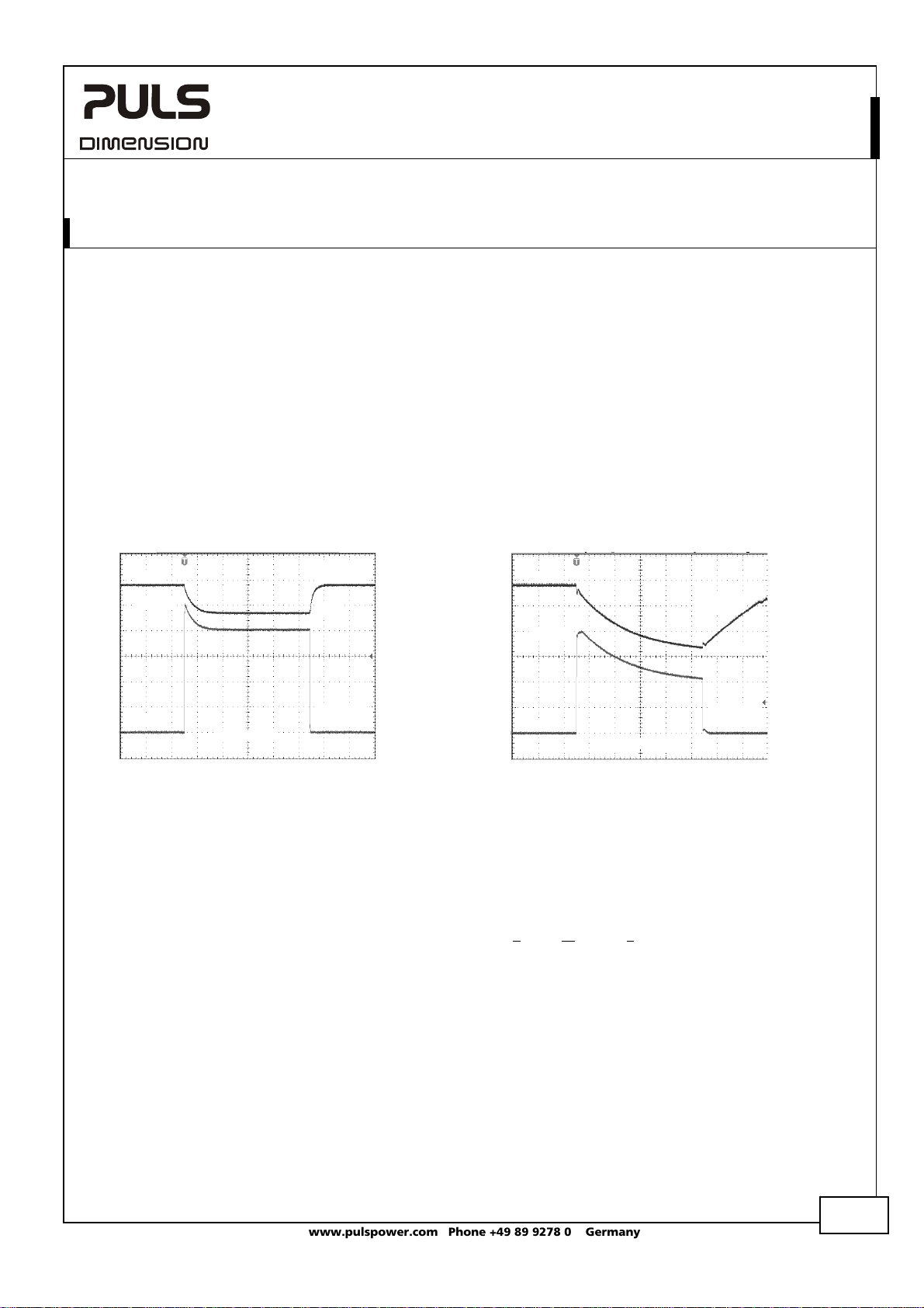
Assuming the input voltage is turned on before such an event, the built-in large sized output capacitors inside the
DC/DC converter can deliver extra current. Discharging this capacitor causes a voltage dip on the output. The following
two examples show typical voltage dips:
Fig. 22-1 Peak loading with 2x the nominal
24V
current for 50ms, typ.
10A
Output
Voltage
18V
Fig. 22-2 Peak loading with 4x the nominal
current for 5ms, typ.
24V
Output
Voltage
20A
11.5V
0A
Peak load 10A (resistive load) for 50ms
Output voltage dips from 24V to 18V.
10ms/DIV
Output
Current
0A
Peak load 20A (resistive load) for 5ms
Output voltage dips from 24V to 11.5V.
1ms/DIV
Output
Current
22.2. BACK-FEEDING LOADS
Loads such as decelerating motors and inductors can feed voltage back to the DC/DC converter. This feature is also
called return voltage immunity or resistance against Back- E.M.F. (E
This DC/DC converter is resistant and does not show malfunctioning when a load feeds back voltage to the DC/DC
converter. It does not matter, whether the DC/DC converter is on or off.
The maximum allowed feed-back-voltage is 30Vdc. The absorbing energy can be calculated according to the built-in
large sized output capacitance which is specified in chapter 5.
lectro Magnetic Force).
22.3. INDUCTIVE AND CAPACITIVE LOADS
The unit is designed to supply any kind of loads, including unlimited capacitive and inductive loads.
Oct 2009 / Rev. 1.3 DS-CD5.241-EN
All parameters are specified at 24V, 5A, 24Vdc input voltage, 25°C ambient and after a 5 minutes run-in time unless otherwise noted.
www.pulspower.com Phone +49 89 9278 0 Germany
17/21
CD5.241
CD-Series
DC/DC Converter 24V, 5A
22.4. CHARGING OF BATTERIES
The DC/DC converter can be used to charge lead-acid or maintenance free batteries. (Two 12V batteries in series)
Instructions for charging batteries:
a) Ensure that the ambient temperature of the DC/DC converter is below 45°C
b) Do not use DC/DC converters in mounting orientations other than the standard mounting orientation (input
terminals on the bottom and output terminals on top of the unit).
c) Set output voltage (measured at no load and at the battery end of the cable) very precisely to the end-of-charge
voltage.
End-of-charge voltage 27.8V 27.5V 27.15V 26.8V
Battery temperature 10°C 20°C 30°C 40°C
d) Use a 6A or 10A circuit breaker (or blocking diode) between the DC/DC converter and the battery.
e) Ensure that the output current of the DC/DC converter is below the allowed charging current of the battery.
f) Use only matched batteries when putting 12V types in series.
g) The return current to the DC/DC converter (battery discharge current) is typ. 26.4mA when the DC/DC converter is
switched off (except in case a blocking diode is utilized).
22.5. EXTERNAL INPUT PROTECTION
The unit is tested and approved for branch circuits up to 50A. An external protection is only required, if the supplying
branch has an ampacity greater than this. Check also local codes and local requirements. In some countries local
regulations might apply.
If an external fuse is necessary or utilized, minimum requirements need to be considered to avoid nuisance tripping of
the circuit breaker. A minimum value of 10A B- or 8A C-Characteristic breaker should be used.
22.6. REQUIREMENTS FOR THE SUPPLYING SOURCE
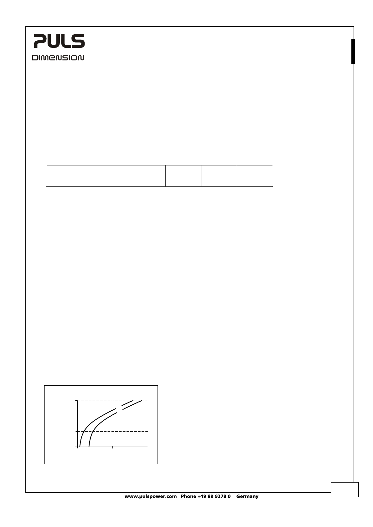
In certain circumstances, the input filter of the DC/DC converter can show a resonant effect which is caused by the
supplying network. Especially when additional external input filters are utilized, a superimposed AC voltage can be
generated on the input terminals of the DC/DC converter which might cause a malfunction of the unit. Therefore,
additional input filters are not recommended. To avoid the resonant effects, the minimal resistance of the supplying
network which depends on the inductance of the input network, shall be above the boundary curve in Fig. 22-3.
Fig. 22-3 External input filter requirements to
Resistance of the
supplying network
100 mOhm
10 mOhm
1 mOhm
avoid filter instabilities
1 Ohm
0.1mH 1mH 10mH
Inductance of the supplying network
a
)
(
b
(
)
(a) max.
(b) typ.
Oct 2009 / Rev. 1.3 DS-CD5.241-EN
All parameters are specified at 24V, 5A, 24Vdc input voltage, 25°C ambient and after a 5 minutes run-in time unless otherwise noted.
www.pulspower.com Phone +49 89 9278 0 Germany
18/21

CD5.241
CD-Series
22.7. PARALLEL USE TO INCREASE OUTPUT POWER
The DC/DC-converter can be paralleled to increase the output power. There are
no feature included which balances the load current between the DC/DCconverters. Therefore some restrictions and limitations apply. The DC/DCconverter with the higher adjusted output voltage draws current until it goes
into current limitation. This means no harm or switch-off to this DC/DC-converter
as long as the ambient temperature stays below 45°C. The CD5.241 can also be
paralleled with power supplies from the DIMENSION CT, QS or QT-series. For
other power supplies consult PULS. Set the “single use / parallel use” jumper to
“parallel use” if such an option is available.
The output voltages of all DC/DC-converters shall be adjusted to the same value
(±100mV) at full load. A fuse or diode on the output of each unit is only required if more than three units are
connected in parallel. This avoid that more than 2 times of the nominal output current can flow backwards into the
DC/DC converter in case the output stage of the DC/DC converter has a defect. If a fuse (or circuit breaker) is used,
choose one with approximately 150% of the rated output current of one DC/DC-converter. Keep an installation
clearance of 15mm (left / right) between two DC/DC-converters and avoid installing the DC/DC-converters on top of
each other. Do not use DC/DC-converters in parallel in mounting orientations other than the standard mounting
orientation (input terminals on the bo
ttom and output terminals on top of the unit).
DC/DC Converter 24V, 5A
Unit A
Input
Unit B
Input
Output
Output
+
-
+
-
Load
+
-
22.8. PARALLEL USE FOR REDUNDANCY
The DC/DC converters can be paralleled for 1+1 redundancy to gain higher system availability. Redundant systems
require a certain amount of extra power to support the load in case one DC/DC converter fails. The simplest way is to
put two DC/DC converters in parallel. This is called a 1+1 redundancy. In case one DC/DC converter fails, the other one
is automatically able to support the load current without any interruption. Redundant systems for a higher power
demand are usually built in an N+1 method. E.g. five DC/DC converters, each rated for 5A are paralleled to build a 20A
redundant system.
Furthermore, 1+1 redundant systems can be built by using a DC/DC converter powered from a battery and a power
supply with AC input.
Please note: This simple way to build a redundant system does not cover failures such as an internal short circuit in
the secondary side of the DC/DC-converter. In such a case, the defect unit becomes a load for the other DC/DCconverters and the output voltage can not be maintained any more. This can only be avoided by utilizing decoupling
diodes which are included in the decoupling module YRM2.DIODE.
Recommendations for building redundant power systems:
a) Use separate input fuses for each DC/DC-converter.
b) Monitor the individual DC/DC-converter units. A DC-ok lamp and a DC-ok contact is included in the redundancy
module YRM2.DIODE. This feature reports a faulty unit.
c) 1+1 Redundancy is allowed up to an ambient temperature of 60°C
N+1 Redundancy is allowed up to an ambient temperature of 45°C
d) It is desirable to set the output voltages of all units to the same value (± 100mV) or leave it at the factory setting.
Oct 2009 / Rev. 1.3 DS-CD5.241-EN
All parameters are specified at 24V, 5A, 24Vdc input voltage, 25°C ambient and after a 5 minutes run-in time unless otherwise noted.
www.pulspower.com Phone +49 89 9278 0 Germany
19/21

CD5.241
CD-Series
DC/DC Converter 24V, 5A
22.9. DAISY CHAINING OF OUTPUTS
Daisy chaining (jumping from one DC/DC-converter output to the next) is allowed as long as the average output
current through one terminal pin does not exceed 25A. If the current is higher, use a separate distribution terminal
block.
Fig. 22-4 Daisy chaining of outputs Fig. 22-5 Using distribution terminals
max 25A!
+
Load
-
Output
+ +
- -
DC/DC
Converter
Input
Output
+ +
- -
DC/DC
Converter
Input
+
Load
Distribution
Terminals
-
Output
+ +
- -
Output
+ +
- -
DC/DC
Converter
Input
DC/DC
Converter
Input
22.10. SERIES OPERATION
DC/DC converters of the exact same type can be connected in series for higher
output voltages. It is possible to connect as many units in series as needed,
providing the sum of the output voltage does not exceed 150Vdc. Voltages with
a potential above 60Vdc are not SELV any more and can be dangerous. Such
voltages must be installed with a protection against touching. Earthing of the
output is required when the sum of the output voltage is above 60Vdc. Avoid
return voltage (e.g. from a decelerating motor or battery) which is applied to the
output terminals. Keep an installation clearance of 15mm (left / right) between
two DC/DC-converters and avoid installing the DC/DC-converters on top of each
Unit A
Input
Unit B
Input
Output
Output
+
-
+
Load
+
-
-
other. Do not use DC/DC-converters in series in mounting orientations other than
the standard mounting orientation (input terminals on the bottom and output terminals on top of the unit).
22.11. USE IN A TIGHTLY SEALED ENCLOSURE
When the DC/DC-converter is installed in a tightly sealed enclosure, the temperature inside the enclosure will be
higher than outside. In such situations, the inside temperature defines the ambient temperature for the DC/DC
converter.
The following measurement results can be used as a reference to estimate the temperature rise inside the enclosure.
The DC/DC-converter is placed in the middle of the box, no other heat producing items are inside the box
Enclosure: Rittal Typ IP66 Box PK 9516 100, plastic, 110x180x165mm
Load: 24V, 4A; (=80%) load is placed outside the box
Input: 24Vdc
Temperature inside enclosure: 42.8°C (in the middle of the right side of the DC/DC converter with a distance of 2cm)
Temperature outside enclosure: 24.0°C
Temperature rise: 18.8K
Oct 2009 / Rev. 1.3 DS-CD5.241-EN
All parameters are specified at 24V, 5A, 24Vdc input voltage, 25°C ambient and after a 5 minutes run-in time unless otherwise noted.
www.pulspower.com Phone +49 89 9278 0 Germany
20/21

C
C
C
C
C
CD5.241
CD-Series
DC/DC Converter 24V, 5A
22.12. MOUNTING ORIENTATIONS
Mounting orientations other than input terminals on the bottom and output on the top require a reduction in
continuous output power or a limitation in the max. allowed ambient temperature. The amount of reduction
influences the lifetime expectancy of the DC/DC converter. Therefore, two different derating curves for continuous
operation can be found below:
Curve A1 Recommended output current.
Curve A2 Max allowed output current (results in approximately half the lifetime expectancy of A1).
Fig. 22-6
Mounting
Orientation A
(Standard
orientation)
Fig. 22-7
Mounting
Orientation B
(Upside down)
Fig. 22-8
Mounting
Orientation C
(Table-top
mounting)
OUTPUT
DC/DC
Converter
INPUT
INPUT
Converter
DC/DC
OUTPUT
Fig. 22-9
Mounting
Orientation D
(Horizontal cw)
INPUT
Converter
DC/DC
OUTPUT
Fig. 22-10
Mounting
Orientation E
(Horizontal ccw)
DC/DC
OUTPUT
INPUT
Converter
Output Current
6A
5
4
3
2
1
0
10 20 30
Output Current
6A
5
4
3
2
1
0
10 20 30
Output Current
6A
5
4
3
2
1
0
10 20 30
Output Current
6A
5
4
3
2
1
0
10 20 30
Output Current
6A
5
4
3
2
1
0
10 20 30
Ambient Temperature
40
Ambient Temperature
40
A
2
A
1
Ambient Temperature
40
A
2
A
1
Ambient Temperature
40
Ambient Temperature
40
50
50
50
50
50
A
1
60°
A
2
A
1
60°
60°
60°
A
2
A
1
60°
Oct 2009 / Rev. 1.3 DS-CD5.241-EN
All parameters are specified at 24V, 5A, 24Vdc input voltage, 25°C ambient and after a 5 minutes run-in time unless otherwise noted.
www.pulspower.com Phone +49 89 9278 0 Germany
21/21
 Loading...