

Page 1
CD5.241
CD-Series
DC/DC Converter 24V, 5A
3. INPUT VOLTAGE
Input voltage nom. DC 24V
Input voltage range 18.0-32.4Vdc full specified
14.4-18.0Vdc maximal 60 seconds or with de-rating see Fig. 5 2
max. 36.0Vdc absolute maximum continuous input voltage with no
damage to the DC/DC converter
Allowed voltage between input
and earth
Allowed input ripple voltage
Turn-on voltage typ. 17.5Vdc steady-state value, see Fig. 3-1
Shut-down voltage typ. 14.0Vdc steady-state value, see Fig. 3-1
typ. 35.0Vdc steady-state value, see Fig. 3-1
Input current typ. 5.5A at 24Vdc input and output 24V, 5A, see Fig. 5 4
Start-up delay typ. 650ms see Fig. 5 3
Rise time typ. 80ms 0mF, 24V, constant current load 5A, see Fig. 5 3
typ. 150ms 5mF, 24V, constant current load 5A, see Fig. 5 3
Turn-on overshoot max. 500mV see Fig. 5 3
Input capacitance typ. 3 000μF external capacitors on the input voltage bus are allowed
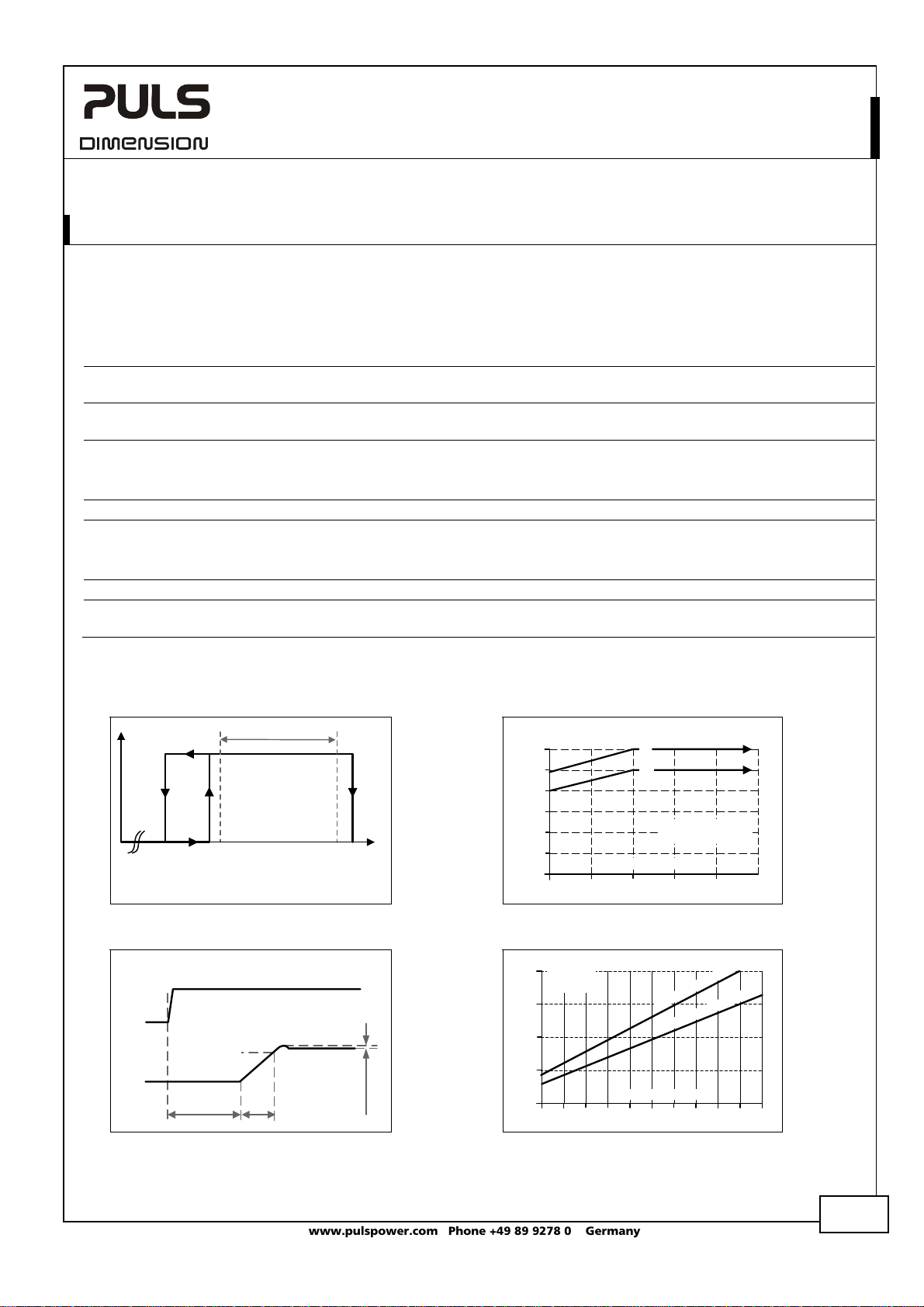
Fig. 3-1 Input voltage range
P
OUT
Shut-down
0Vdc
14.
Rated input range
Turn-on
0Vdc
17.5Vdc
18.
Fig. 3-3 Turn-on behavior, definitions Fig. 3-4 Input current vs. output load
Input
Voltage
Output
Voltage
- 5%
Start-up
delay
Rise
Time
max. 60Vdc or
in case the output voltage is not grounded.
42.2Vac
max. 5Vpp 47Hz-40kHz, the momentary input voltage must always
be within the specified limits.
without any limitations.
Fig. 3-2 Allowable output current below 18V
Output Current
6A
5
4
3
2
1
0
14 16 18 20 24Vdc
Input
8A
Current,
typ.
6
4
2
0
1
input voltage
Input Voltage
Output Current
2.5
1.5 2 3
(
a
)
)
(
b
(a) Ambient < 45°C
(b) Ambient < 60°C
t
u
p
n
I
p
n
I
3.5
4
4.5
22
c
d
V
8
1
:
c
Vd
4
2
:
t
u
5.5
5
6A
4Vdc
32.
V
35.0Vdc
ershoot
Ov
IN
Oct 2009 / Rev. 1.3 DS-CD5.241-EN
All parameters are specified at 24V, 5A, 24Vdc input voltage, 25°C ambient and after a 5 minutes run-in time unless otherwise noted.
www.pulspower.com Phone +49 89 9278 0 Germany
4/21
Page 2
CD5.241
CD-Series
DC/DC Converter 24V, 5A
4. SOFT-START AND INPUT INRUSH CURRENT SURGE
Inrush current limitation
An active inrush limitation circuit (inrush limiting resistor which is bypassed by a relay contact) limits the input inrush
current after turn-on of the input voltage.
The charging current into EMI suppression capacitors is disregarded in the first microseconds after switch-on.
Inrush current max. 1.6A
typ. 1.2A
Inrush energy typ. negligible -25°C to +70°C, input: 24Vdc
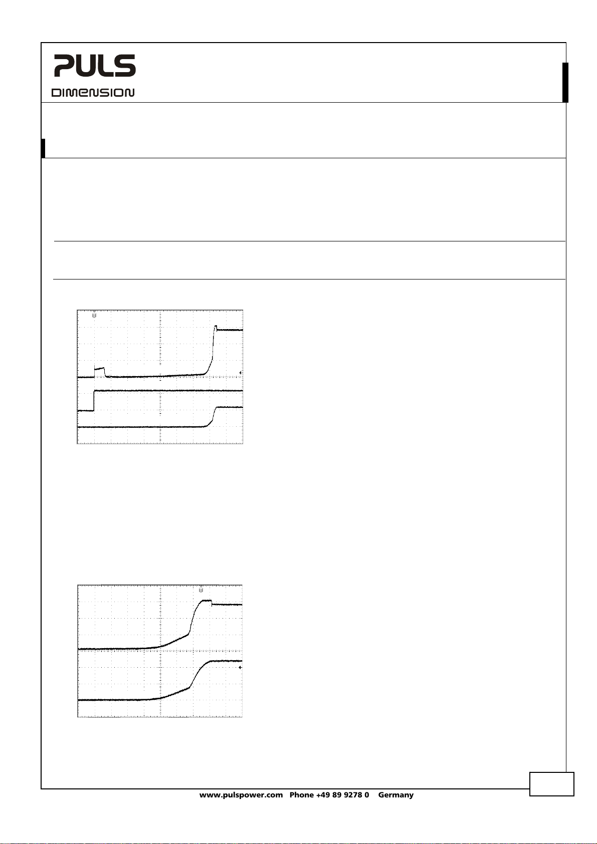
Fig. 4-1 Input inrush current, typical behavior
Input Current
Input Voltage
Output Voltage
-25°C to +70°C, input: 24Vdc
peak
-25°C to +70°C, input: 24Vdc
peak
Input: 24Vdc
Output: 24V, 5A, constant current load
Ambient: 25°C
Upper curve: Input current 2A / DIV
Middle curve: Input voltage 20V / DIV
Lower curve: Output voltage 20V / DIV
Time basis: 100ms / DIV
Soft-start function:
After the DC/DC converter is turned on, the internal output current rises slowly to its nominal value. This method
charges the output capacitors (internal and external capacitors) slowly and avoids high input currents during turn-on.
High input currents can produce a high voltage drop on the input wiring (especially with long and thin cables) which
reduces the terminal voltage on the DC/DC converter. If the terminal voltage is below the shut-down voltage, the
DC/DC converter will turn-off and will make a new start-up attempt. This effect is avoided with the integrated softstart function. Please note, that this function increases the rise time of the output voltage by a small amount.
Fig. 4-2 Soft-start behavior
Input Current
Output Voltage
Input: 24Vdc
Output: 24V, 5A, constant current load
Ambient: 25°C
No additional external output capacitors
Upper curve: Input current 2A / DIV
Lower curve: Output voltage 10V / DIV
Time basis: 20ms / DIV
Oct 2009 / Rev. 1.3 DS-CD5.241-EN
All parameters are specified at 24V, 5A, 24Vdc input voltage, 25°C ambient and after a 5 minutes run-in time unless otherwise noted.
www.pulspower.com Phone +49 89 9278 0 Germany
5/21
Page 3
A
c
CD5.241
CD-Series
DC/DC Converter 24V, 5A
5. OUTPUT
Output voltage nom. 24V
Adjustment range min. 23-28V guaranteed
max. 30V at clockwise end position of potentiometer
Factory setting 24.1V ±0.2%, at full load, cold unit
Line regulation max. 25mV Input voltage variations between 18 to 32.4Vdc
Load regulation max. 100mV static value, 0A Æ 5A
Ripple and noise voltage max. 50mVpp 20Hz to 20MHz, 50Ohm
Output capacitance typ. 2 200μF
Output current nom. 6A at 24V, ambient < 45°C, see Fig. 5-1
nom. 5A at 24V, ambient < 60°C, see Fig. 5-1
nom. 5.2A at 28V, ambient < 45°C, see Fig. 5-1
nom. 4.3A at 28V, ambient < 60°C, see Fig. 5-1
Output power nom. 144W for ambient temperatures < 45°C
nom. 120W for ambient temperatures < 60°C
Short-circuit current min. 7A continuous current, short circuit impedance 200mOhm
max. 10A continuous current, short circuit impedance 200mOhm
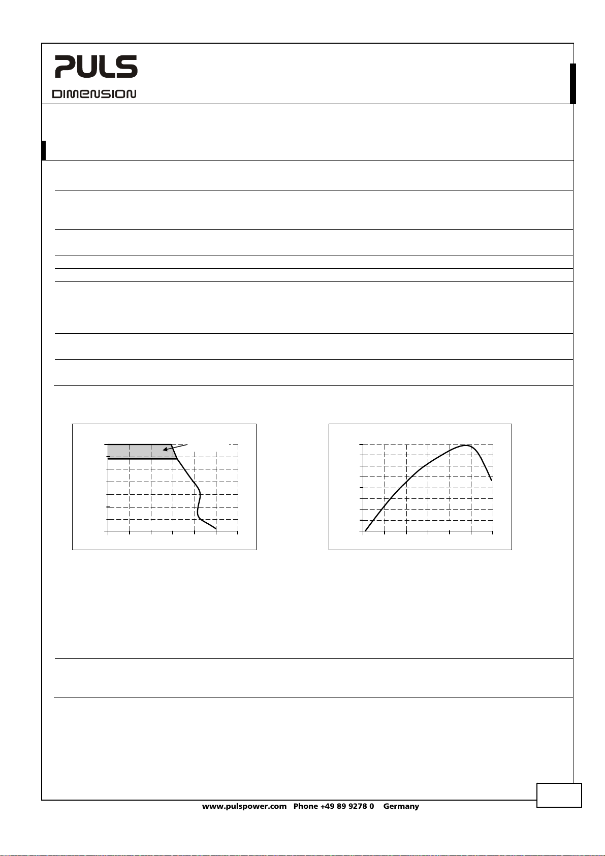
Fig. 5-1 Output voltage vs. output current at
Output Voltage
24Vdc input voltage, typ.
28V
24
20
16
12
8
4
0
Output Current
048
Adjustment
Range
12
1062
Fig. 5-2 Current limitation vs. input voltage,
(23V constant voltage load), typ.
Output Current
6.6A
6.5
6.4
6.3
6.2
6.1
6.0
5.9
5.8
15 21 27
Input Voltage
Peak current capability (up to several milliseconds)
The DC/DC converter can deliver a peak current, which is higher than the specified short term current. This helps to
start current demanding loads or to safely operate subsequent circuit breakers.
The extra current is supplied by the output capacitors inside the DC/DC converter. During this event, the capacitors will
be discharged and causes a voltage dip on the output. Detailed curves can be found in chapter 22.1.
Peak current voltage dips typ. from 24V to 18V at 10A for 50ms, resistive load
typ. from 24V to 15V at 20A for 2ms, resistive load
typ. from 24V to 11.5V at 20A for 5ms, resistive load
302418 33Vd
Oct 2009 / Rev. 1.3 DS-CD5.241-EN
All parameters are specified at 24V, 5A, 24Vdc input voltage, 25°C ambient and after a 5 minutes run-in time unless otherwise noted.
www.pulspower.com Phone +49 89 9278 0 Germany
6/21
Page 4

CD5.241
CD-Series
DC/DC Converter 24V, 5A
6. HOLD-UP TIME
The input side of the DC/DC converter is equipped with a bulk capacitor which keeps the output voltage alive for a
certain period of time when the input voltage dips or is removed. The bulk capacitor can be discharged by loading the
DC/DC converter on the output side or through a load which is parallel to the input. There is no protection in the
DC/DC converter which prevents current from flowing back to the input terminals. If prevention is needed, an external
diode should be used.
Hold-up Time typ. 11.8ms input 24Vdc, output: 24Vdc, 2.5A, see Fig. 6-1
typ. 6ms input 24Vdc, output: 24Vdc, 5A, see Fig. 6-1
Fig. 6-1 Hold-up time vs. input voltage
Hold-up Time
12ms
10
8
6
4
2
0
Input Voltage
18 20 22 24 28Vdc
a
)
(
(
)
b
(
)
c
)
(
d
(a) 24V, 2.5A, typ.
(b) 24V, 2.5A, min.
(c) 24V, 5A, typ.
(d) 24V, 5A, min.
26
Fig. 6-2 Shut-down test setup Fig. 6-3 Shut-down behavior, definitions
Intput
DC/DC
S1
DC
Source
+
-
Converter
Input
CD5
Output
+
+
Load
-
-
Voltage
Output
Voltage
S1 opens
- 5%
Hold-up Time
Note: At no load, the hold-up time can be up to several seconds. The green DC-ok lamp is also on during this time.
Oct 2009 / Rev. 1.3 DS-CD5.241-EN
All parameters are specified at 24V, 5A, 24Vdc input voltage, 25°C ambient and after a 5 minutes run-in time unless otherwise noted.
www.pulspower.com Phone +49 89 9278 0 Germany
7/21
Page 5

A
A
c
c
CD5.241
CD-Series
7. EFFICIENCY AND POWER LOSSES
Input 24Vdc
Efficiency typ. 90.3% at 24V, 5A
Power losses typ. 0.7W at no output load
typ. 6.2W at 24V, 2.5A
typ. 12.9W at 24V, 5A
typ. 16.3W at 24V, 6A
Fig. 7-1 Efficiency vs. output current at 24V
Efficiency
91%
90
89
88
87
86
85
1
output and 24Vdc input voltage, typ.
Output Current
245
3
6
Fig. 7-3 Efficiency vs. input voltage at 24V,
Efficiency
91%
90.5
90.0
89.5
89.0
88.5
88.0
5A, typ.
Input Voltage
18 20 22 26 28 32Vd
24 30
Fig. 7-2 Losses vs. output current at 24V
output and 24Vdc input voltage, typ.
Power Losses
18W
15
12
9
6
3
0
012 456
Fig. 7-4 Losses vs. input voltage at 24V, 5A,
typ.
Power Losses
18W
15
12
9
6
3
0
18 20 24 26 28 32Vd
DC/DC Converter 24V, 5A
Output Current
3
Input Voltage
22 30
Oct 2009 / Rev. 1.3 DS-CD5.241-EN
All parameters are specified at 24V, 5A, 24Vdc input voltage, 25°C ambient and after a 5 minutes run-in time unless otherwise noted.
www.pulspower.com Phone +49 89 9278 0 Germany
8/21
Page 6

CD5.241
CD-Series
DC/DC Converter 24V, 5A
10. TERMINALS AND WIRING
Type screw terminals screw terminals
Solid wire 0.5-6mm2 0.5-6mm2
Stranded wire 0.5-4mm2 0.5-4mm2
American Wire Gauge 20-10 AWG 20-10 AWG
Wire stripping length 7mm / 0.275inch 7mm / 0.275inch
Screwdriver 3.5mm slotted or
Recommended tightening torque 1Nm, 9lb.in 1Nm, 9lb.in
Instructions:
a) Use appropriate copper cables that are designed for an operating temperature of:
60°C for ambient up to 45°C and
75°C for ambient up to 60°C minimum.
b) Follow national installation codes and installation regulations!
c) Ensure that all strands of a stranded wire enter the terminal connection!
d) Up to two stranded wires with the same cross section are permitted in one connection point.
e) Do not load the terminals with more than 25A! See section 22.9
f) Screws of unused terminal compartments should be securely tightened.
g) Ferrules are allowed, but not required
Input Output
Pozidrive No 2
3.5mm slotted or
Pozidrive No 2
11. RELIABILITY
Input 24Vdc
Lifetime expectancy
65 000h at 24V, 5A and 40°C
37 000h at 24V, 6A and 40°C
185 000h at 24V, 5A and 25°C
MTBF
**) SN 29500, IEC 61709 1 178 000h at 24V, 5A and 40°C
1 932 000h at 24V, 5A and 25°C
MTBF
**) MIL HDBK 217F 625 000h at 24V, 5A and 40°C; Ground Benign GB40
838 000h at 24V, 5A and 25°C; Ground Benign GB25
*) The Lifetime expectancy shown in the table indicates the minimum operating hours (service life) and is determined by the lifetime
expectancy of the built-in electrolytic capacitors. Lifetime expectancy is specified in operational hours and is calculated according to the
capacitor’s manufacturer specification. The prediction model allows only a calculation of up to 15 years from date of shipment.
**) MTBF stands for Mean Time Between Failure, which is calculated according to statistical device failures, and indicates reliability of a
device. It is the statistical representation of the likelihood of a unit to fail and does not necessarily represent the life of a product.
*) 183 000h at 24V, 2.5A and 40°C
Oct 2009 / Rev. 1.3 DS-CD5.241-EN
All parameters are specified at 24V, 5A, 24Vdc input voltage, 25°C ambient and after a 5 minutes run-in time unless otherwise noted.
www.pulspower.com Phone +49 89 9278 0 Germany
10/21
Page 7

CD5.241
CD-Series
DC/DC Converter 24V, 5A
12. EMC
The DC/DC converter is suitable for applications in industrial environment as well as in residential, commercial and
light industry environment without any restrictions. The CE mark indicates conformance with EMC guideline
89/336/EEC, 93/68/EEC and 2004/108/EC and the low-voltage directive (LVD) 73/23/EWG and 2006/95/EC. A detailed EMC
report is available on request.
EMC Immunity
Electrostatic discharge EN 61000-4-2 Contact discharge
Electromagnetic RF field EN 61000-4-3 80MHz-2.7GHz 10V/m Criterion A
Fast transients (Burst) EN 61000-4-4 Input lines
Surge voltage on input EN 61000-4-5 + Æ - 1kV Criterion A
Surge voltage on output EN 61000-4-5 + Æ -
Conducted disturbance EN 61000-4-6 0.15-80MHz 10V Criterion A
Criterions:
A: DC/DC converter shows normal operation behavior within the defined limits.
C: Temporary loss of function is possible. DC/DC converter may shut-down and restarts by itself. No damage or hazards for the DC/DC
converter will occur.
EMC Emission
Conducted emission
Radiated emission EN 55011, EN 55022 Class B
This device complies with FCC Part 15 rules.
Operation is subjected to following two conditions: (1) this device may not cause harmful interference, and (2) this
device must accept any interference received, including interference that may cause undesired operation.
Switching frequency
Generic standards: EN 61000-6-1 and EN 61000-6-2
8kV
Air discharge
Output lines
+/- Æ chassis ground
+ / - Æ chassis ground
Generic standards: EN 61000-6-3 and EN 61000-6-4
IEC/CISPR 16-1-2, IEC/CISPR 16-2-1
Variable between 90kHz and 135kHz depending on load and input voltage
(output current > 0.5A)
15kV
4kV
2kV
2kV Criterion A
500V
500V
Class B, input lines
(Limits for DC power ports)
Criterion A
Criterion A
Criterion A
Criterion A
Criterion A
Criterion A
Oct 2009 / Rev. 1.3 DS-CD5.241-EN
All parameters are specified at 24V, 5A, 24Vdc input voltage, 25°C ambient and after a 5 minutes run-in time unless otherwise noted.
www.pulspower.com Phone +49 89 9278 0 Germany
11/21
Page 8

C
CD5.241
CD-Series
DC/DC Converter 24V, 5A
13. ENVIRONMENT
Operational temperature
Storage temperature -40 to +85°C (-40°F to 185°F) for storage and transportation
Output de-rating 1.6W/°C 45-60°C (113°F to 140°F)
3W/°C 60-70°C (140°F to 158°F)
Humidity
**) 5 to 95% r.H. IEC 60068-2-30
Vibration sinusoidal 2-17.8Hz: ±1.6mm; 17.8-500Hz: 2g
Shock 30g 6ms, 20g 11ms
Altitude 0 to 6000m (0 to 20 000ft) reduce output power or ambient temperature
Altitude de-rating 7.5W/1000m or 5°C/1000m above 2000m (6500ft), see Fig. 13-2
Over-voltage category III IEC 62103, EN 50178, altitudes up to 2000m
II altitudes from 2000m to 6000m
Degree of pollution 2 IEC 62103, EN 50178, not conductive
*) Operational temperature is the same as the ambient temperature and is defined as the air temperature 2cm below the unit.
**) Do not energize while condensation is present
Fig. 13-1 Output current vs. ambient temp. Fig. 13-2 Output current vs. altitude at 24V
Allowable Output
Current at 24V
6A
5
4
3
2
1
0
-25 0 20 40
Ambient Temperature
*) -25°C to +70°C (-13°F to 158°F) reduce output power according Fig. 13-1
IEC 60068-2-6
2 hours / axis
IEC 60068-2-27
3 bumps / direction, 18 bumps in total
above 2000m sea level.
s
h
o
r
t
t
e
r
m
c
o
n
t
i
n
u
o
u
s
70°
60
Allowable Output
Current at 24V
6A
5
4
3
2
A
.
.
.
m
a
T
b
<
6
.
B
.
.
m
a
T
<
b
5
1
C
.
0
0 2000 4000
.
.
m
a
T
<
b
4
B
0
°
C
0
°
C
0
°
C
s
h
o
C
A
Altitude
r
t
t
6000m
e
r
m
14. PROTECTION FEATURES
Output protection Electronically protected against overload, no-load and short-circuits
Output over-voltage protection typ. 31Vdc
max. 32Vdc
in case of an internal power supply defect, a redundant
circuit limits the maximum output voltage. The output
shuts down and automatically attempts to restart.
Reverse input polarity protection Included unit does not start when input voltage is reversed
Output over-current protection electronically limited *) see Fig. 5-1
Degree of protection IP 20 EN/IEC 60529
Penetration protection > 3.5mm e.g. screws, small parts
Over-temperature protection yes output shut-down with automatic restart
Input transient protection MOV Metal Oxide Varistor
Internal input fuse T10A H.B.C. not user replaceable
*) In case of a protection event, audible noise may occur.
Oct 2009 / Rev. 1.3 DS-CD5.241-EN
All parameters are specified at 24V, 5A, 24Vdc input voltage, 25°C ambient and after a 5 minutes run-in time unless otherwise noted.
www.pulspower.com Phone +49 89 9278 0 Germany
*)
12/21
Page 9
CD5.241
CD-Series
DC/DC Converter 24V, 5A
15. SAFETY FEATURES
Input / output separation
PELV IEC/EN 60204-1, EN 50178, IEC 62103, IEC 60364-4-41
Class of protection III PE (Protective Earth) connection not required. A
Isolation resistance > 5MOhm input to output, 500Vdc
PE resistance < 0.1Ohm between housing and Chassis Ground terminal
Touch current (leakage current) The leakage current which is produced by the DC/DC converter itself depends on the
*) Double or reinforced insulation
*) SELV IEC/EN 60950-1
connection of the “Chassis Ground” pin to earth is
recommended for best EMI performance
input voltage ripple and need to be investigated in the final application.
For a smooth DC input voltage, the produced leakage current is less than 100μA.
16. DIELECTRIC STRENGTH
The output voltage is floating and has no ohmic connection to the ground.
Type and factory tests are conducted by the manufacturer. Field tests may be conducted in the field using the
appropriate test equipment which applies the voltage with a slow ramp (2s up and 2s down). Connect all phaseterminals together as well as all output poles before conducting the test. When testing, set the cut-off current settings
to the value in the table below.
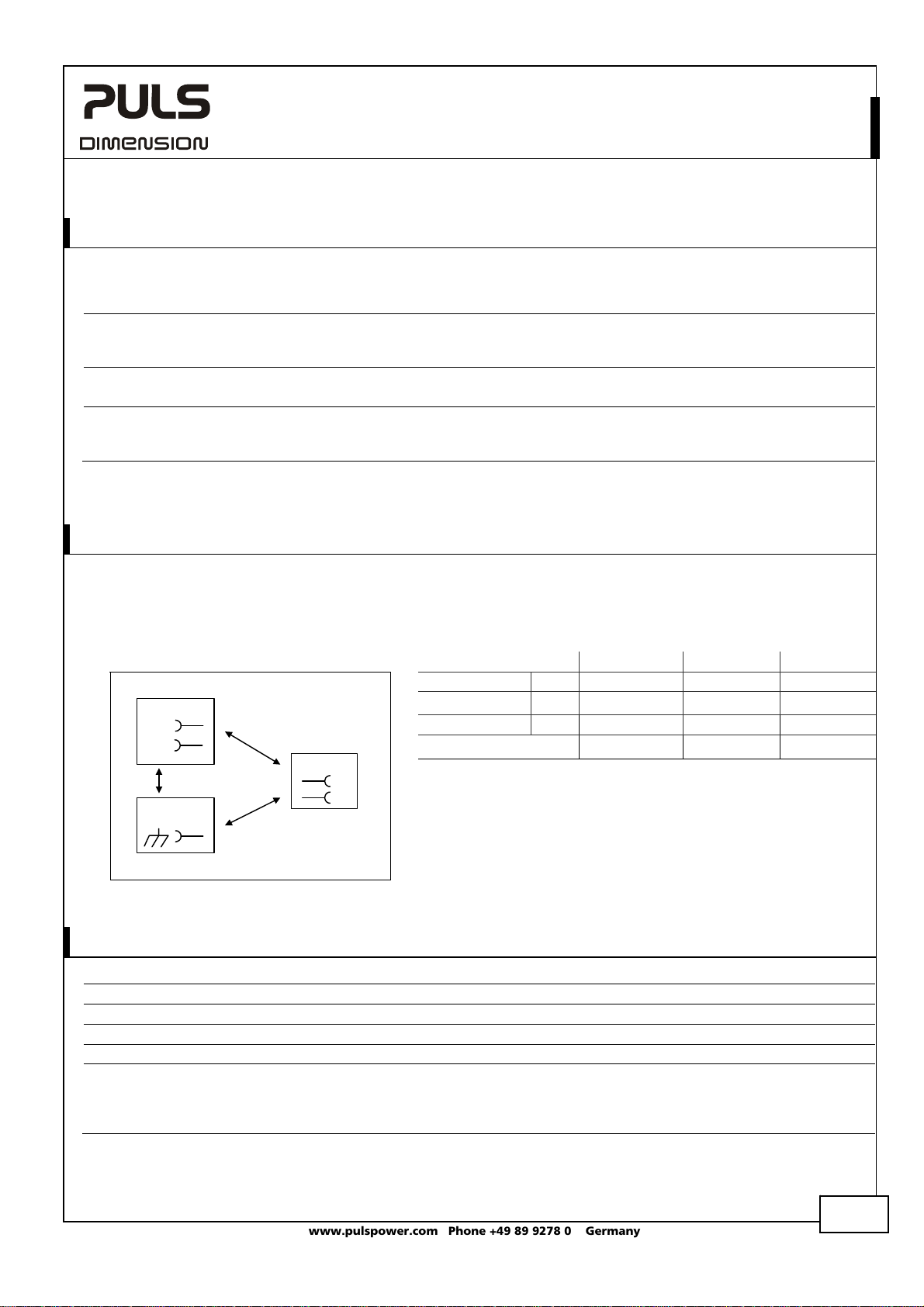
Fig. 16-1 Dielectric strength
Input
+
-
A
Chassis
ground
B
Output
+
C
-
Type test 60s 1500Vac 1500Vac 500Vac
Factory test 5s 1500Vac 1500Vac 500Vac
Field test 5s 1000Vac 1000Vac 500Vac
Cut-off current setting > 30mA > 30mA > 12mA
To fulfill the PELV requirements according to EN60204-1 § 6.4.1, we
recommend that either the + pole, the – pole or any other part of
the output circuit shall be connected to the protective earth
system. This helps to avoid situations in which a load starts
unexpectedly or can not be switched off when unnoticed earth
faults occur.
A B C
17. USED SUBSTANCES
The unit does not release any silicone and is suitable for the use in paint shops.
The unit conforms to the RoHS directive 2002/96/EC
Electrolytic capacitors included in this unit do not use electrolytes such as Quaternary Ammonium Salt Systems.
Plastic housings and other molded plastic materials are free of halogens, wires and cables are not PVC insulated.
The production material within our production does not include following toxic chemicals:
Polychlorized Biphenyl (PCB), Polychlorized Terphenyl (PCT), Pentachlorophenol (PCP), Polychlorinated naphthalene
(PCN), Polybrom Biphenyll (PBB), Polybrom Bipheny-oxyd (PBO), Polybrominated Diphenylether (PBDE), Polychlorinated
Diphenylether (PCDE), Polydibromphenyl Oxyd (PBDO), Cadmium, Asbest, Mercury, Silicia
Oct 2009 / Rev. 1.3 DS-CD5.241-EN
All parameters are specified at 24V, 5A, 24Vdc input voltage, 25°C ambient and after a 5 minutes run-in time unless otherwise noted.
www.pulspower.com Phone +49 89 9278 0 Germany
13/21
Page 10

CD5.241
CD-Series
DC/DC Converter 24V, 5A
18. APPROVALS
IEC 60950-1
IEC 61010-1
UL 508
IND. CONT. EQ.
ANSI / ISA 12.12.01-2007
IND. CONT. EQ.
UL 60950-1
UL 61010-1
ANSI / ISA 12.12.01-2007
The unit is suitable for use in Class I Division 2 Groups A, B, C, D locations
Substitution of components may impair suitability for Class I Division 2 environment.
Do not disconnect equipment unless power has been switched off. Wiring must be
in accordance with Class I, Division 2 wiring methods of the National Electrical Code,
NFPA 70, and in accordance with other local or national codes.
CSA 22.2 No107.1-01
ATEX
II 3G Ex nAC II T4
Marine
CB Scheme,
Information Technology Equipment
CB Scheme,
Electrical Equipment for Measurement, Control and
Laboratory Use
LISTED for use in U.S.A. (UL 508) and
Canada (C22.2 No. 107-1-01) E-File: E198865
Industrial Control Equipment
RECOGNIZED E327416 recognized for use in U.S.A. (ANSI /
ISA 12.12.01-2007) and Canada (C22.2 No. 213-M1987)
Hazardous Location Class I Div 2 T4 Groups A,B,C,D
RECOGNIZED for the use in U.S.A. (UL 60950-1) and Canada
(C22.2 No. 60950-1)
E-File: E137006
Information Technology Equipment, Level 3
E-File: E326782
Electrical Equipment for Measurement, Control and
Laboratory Use
RECOGNIZED E246877 recognized for use in U.S.A. (ANSI /
ISA 12.12.01-2007) and Canada (C22.2 No. 213-M1987)
Hazardous Location Class I Div 2 T4 Groups A,B,C,D
CSA approval for Canada
CAN/CSA C22.2 No 107-1; CAN/ CSA 60950-1-03; UL60950-1
Suitable for use in Class 1 Zone 2 Groups IIa, IIb and IIc
locations. Number of ATEX certificate: EPS 08 ATEX 1 142 X.
DC/DC converter must be built-in in an IP54 enclosure.
GL (Germanischer Lloyd) classified and
ABS (American Bureau for Shipping) PDA
Environmental category: C, EMC2
Marine and offshore applications
19. FULFILLED STANDARDS
EN 61558-2-17 Safety of Power Transformers
EN/IEC 60204-1 Safety of Electrical Equipment of Machines
EN/IEC 61131-2 Programmable Controllers
EN 50178, IEC 62103 Electronic Equipment in Power Installations
Oct 2009 / Rev. 1.3 DS-CD5.241-EN
All parameters are specified at 24V, 5A, 24Vdc input voltage, 25°C ambient and after a 5 minutes run-in time unless otherwise noted.
www.pulspower.com Phone +49 89 9278 0 Germany
14/21
 Loading...