

Page 1
AP486
4 Outputs
◆
19" Power Supply, 130 Watt
◆ High efficiency: 83%
◆ ACin wide range: 88...265V AC
◆ DCin wide range: 100...300V DC
◆ 12 HP plug in width
◆ H15 standard pinout
◆ Power rail sharing
◆ Over Temperature Protection (OTP)
◆ Meets EMC standards: VDE 0160/2, EN 61000-4
NAMUR, EN 50081-1 (EN 55022/B) and EN 50082-2
248
EN 60 950
EN 60 601-1
Power Supply AP486
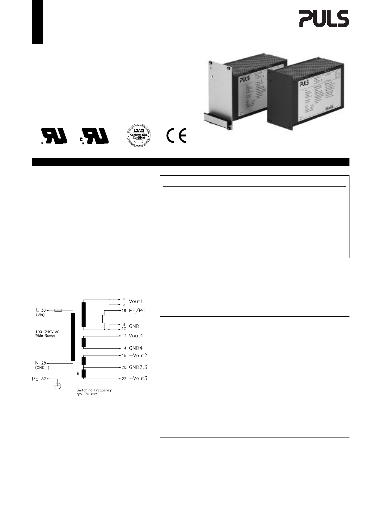
This 4-output power supply u ses a two-step wide-rang
e converter. It operates over a wide range (88 - 265V
AC) without any switch over. Hold-up tim e is 210 m s at
230V AC and load distribution is flexible.
EMC compatibility is a major feature. It has low spurious noise, and noise suppression meets VDE 0871
class B.
Noise immunity meets EN 61000-4 and VDE 0160 class
2, even at full load. Over-voltage and over-temperature protection avoid problems in extreme wo rking environments.
Schematic:
www.puls-power.de
See the web for current data sheet version:
Vout [DC] Iout Pout Features Order-No.
Vout1
Max. total power: 130W
Vout1
Max. total power: 130W
"F" appended to Order No. means front panel 12HP included and fitted.
Accessories: H15 connector, 6.3mm flat contacts:
Warranty: 2 years from date of delivery.
5.15V 10A
2
+12V 4A
3
–12V 4A
4
24V 5A
5.15V 10A
2
+15V 4A
3
–15V 4A
4
24V 5A
H15 connector with soldering pins:
51.5W PF, OVP, OTP
48W
48W
120W
51.5W PF, OVP, OTP
60W
60W
120W
AP486.112
AP486.122
ZP100
ZP120
Output
Voltage Vout1,2,3,4 Fixed.
Accuracy Vout1 max. ± 2% Includes: production-adjustment,
Vout2/3 max. ± 2% (.112: + 4%) line regulation,
Vout4 max. ± 2% and load regulation.
Sense lines None Not available.
Minimum load 0.5A To reach the specified values.
Output power Pout max. 130W Total power.
Noise, Ripple Vout1/2/3/4 max. 20mVpp 20Hz...200kHz.
incl. spikes max. 30mVpp 20Hz...20MHz.
Over-voltage protection typ. 6.2V Threshold accuracy ± 8%.
Derating 3 W/K +55° to +70°C Ta.
Operating indicator 4 green LED On the front, Vout1,2,3,4.
Isolation Vout to Vin SELV EN 60 950, VDE 0805.
All outputs are protected against open-circuit, short-circuit, and overload.
Mechanical: 12HP/3U board (DIN 41494),
Al/Mg alloy cover for component side,
plastic cover for bottom side,
LxWxH = 171.93 x 60.96 x 100mm,
the length includes the connector, see page 4.
Weight: App. 800g
Connector: H15 (DIN 41612), coding option,
Input
Line input AC 100...240V AC Wide-range converter.
Range 88...265V AC Full spec.
⋅
Line input DC 275V DC Wide-range converter.
Range 100...300V DC Full spec.
⋅
Line frequency 47...63Hz DC or 400Hz, see page 2.
Input current rms. max. 2.6A / 1.4A @ 115 / 230V AC.
Noise suppression EN 55 022/B 10kHz...30MHz.
Specifications are valid at 230V AC, unless otherwise stated. They are subject to change without prior
notice.
Page 2

AP486 ◆ 4 Outputs ◆ 19" Power Supply ◆ 130 Watt
Output
(continued)
5.15V ±12V 24V 5.15V ±15V 24V
Voltage regulation:
AP486.112 AP486.122
Line regulation max. % 0.3 4 (0.2) 1 0.3 4 (0.2) 1
⋅
Load regulation stat. ∆ U
⋅
Load regulation dyn. ∆ U
⋅
Response time t
Temperature coefficient typ. %/K 0.015 0.015
⋅
max. % ±1 −0.5 −3 ±1 −0.5 −3
stat
max. % ±7 ±1 ±1.5 ±7 ±1 ±1.5
dyn
max. ms 1 0.3 1 1 0.3 1
s
Ripple max. mVpp 15 3 30 15 3 30
max. mVpp 25 120 (3) 90 25 120 (3) 90
incl. spikes max. mVpp 35 10 35 35 10 35
⋅
max. mVpp 35 120 (10) 90 35 120 (10) 90
Current limitation
Threshold Vout1 typ. A 14 14
⋅
Threshold Vout1/2/3/4 typ. W 145 145
⋅
Current at overload max. A 18 14 7 18 11 7
⋅
Minimum load Vout1 max. A 0.5 0.5
Start delay t
Vout rise-up time t
typ. ms 750 750
Delay
typ. ms 10 1 0
Rise
On and off characteristic
Input (continued)
AC input range V AC 88...265
DC-input range V DC 100...300
Derated AC range V AC 70...88
Derated DC range V DC 85...100
V DC 300...380
Frequency range Hz 47...63
Derated frequency range Hz 63...400
In-rush current max. A 70
Hold-up time min. ms 15
min. ms 130
Power factor λ typ. 0.65
Internal fuse 5x20mm T4A/250V
Input range selection Wide range
(IEC127/2-5)
88...265V AC, minimum load at Vout1,
Iout = 100% (60%).
Iout = 50%, ∆ Iout = ±50%, min imum load
at Vout1, @ 230 V AC.
10%...90%...10% load change,
rise time dt = typ. 20µs.
Till ∆Vout is within < 0,5%of final value.
20Hz...200kHz, 230V AC, Iout = 100%.
20Hz..200kHz, 88V AC, Iout = 100% (60%).
20Hz...20MHz, 230V AC, Iout = 100%.
20Hz..20MHz, 88V AC, Iout = 100% (60%).
Fixed.
Fixed, total power, exceeding leads to switch
off with periodic restart.
Dependent on current at Vout2,3,4 and Vin.
After switch on.
Without C-Load.
Approximately monotonic.
Full spec.
Full spec.
Diff. values for hold-up time, input current,
ripple and Pout; for details contact supplier,
(no start below 100V).
Full spec, but air- and leakage distances not
longer than stated in VDE 0805.
Full spec.
Increased leakage current.
Wait min. 30s before switching on again,
(cold-start).
@ 88V AC, Iout = 100%.
@ 196V AC, Iout = 100%, see page 3.
@ 98V AC, Iout = 100%.
To replace, see page 4.
95%
t
0
t
DelaytRise
Vout
Logic Functions
Power Fail signal PF Power fail + Vout1 watch
PF low 5ms before Vout1 < 4.75V
⋅
PF high, if ACin > 75V AC and Vout1 > 4.7V
⋅
Hold-up time
from power failure to PF-signal min. ms 7
⋅
from PF-signal min. ms 5
⋅
Electromagnetic Compatibility
Emissions according to 50081-1
Radio interference, EN 55 011,
⋅
EN 55 022
Immunity according to 50082-2
Electrostatic discharge ESD, EN 61000-4-2
⋅
Radiated fields, EN 61000-4-3
⋅
Fast transients, EN 61000-4-4
⋅
Surge transients, EN 61000-4-5
⋅
Transient voltage, IEC 255
⋅
NAMUR-prescriptions
⋅
Over-voltage resistance (PULS standard)
⋅
Class B
8kV direct discharge (level 4)
15kV air discharge (level 4)
10V / m (level 3)
4kV (level 4)
2kV (level 3)
2kV (level 4) cap coupling
4kV (isolation class 4)
2kV (isolation class 4)
5kV
Satisfied
300V AC / 0.5s
Open-collector signal (I
See diagram on page 3, Iout = 100%.
@ 88V ACin.
EN 50081-2 is also satisfied
Conducted 10kHz...30MHz.
EN 50082-1 is also satisfied
ACin, Vout and signal lines: length = 1m.
Coupled to ACin line.
Coupled to DCout line.
Coupled to Vout and signal lines.
Common mode, unit on.
Differential mode, unit on.
Common mode, unit off.
= 5mA), see pg. 3
max
Page 3

4 Outputs ◆ 19" Power Supply ◆ 130 Watt ◆ AP486
PF-Signal and Hold-Up Time
Min. Hold-Up Time
1000
100
Hold-Up Time [ms]
10
80 110 140 170 200 230 260 290
Input Voltage [Vac]
Typ. Derating over Temperature
130W
100W
70W
50W
30W
Protection
Unit protection
Overload Yes Total-power limit.
⋅
Short-circuit proof Yes Auto restart.
⋅
Open-circuit proof Yes
⋅
Over-temp. (OTP) typ. +105° C Transformer temp, switch off,
⋅
typ. +1 00 ° C Transformer temp, switch on,
(automatically).
Reverse battery prot. Yes
⋅
ACin range selection Wide range
⋅
Load protection
Over-voltage (OVP) Yes
⋅
Threshold typ. 6.2V Valid for Vout 1.
Accuracy max.± 8%
Method By thyristor.
Safety
Electrical safety
Test voltage (each unit) 3kV AC Primary / secondary.
⋅
according to EN 60 950 2.5kV AC Primary / PE.
t = 2sec 500V AC Secondary / PE.
Air- and leakage distance 6.4 / 8mm Primary / secondary.
⋅
3.2 / 4mm Primary / PE .
Isolation resistance min. 5M
⋅
Protection class
⋅
PE resistance < 0.1
⋅
Protection system IP20 DIN 40050, IEC 529.
⋅
Leakage current max. 0.45mA EN 60 950 (47-63 Hz line) .
⋅
Safe low voltage SELV EN 60 950, VDE 0805, VDE 0160.
⋅
Over-voltage class
⋅
Touch safety Finger test VDE 0100 §6, EN 60 950, VBG4.
Penetration protection
Ω
Ι
Ω
ΙΙ
> ∅
3mm e.g. screws, small parts etc.
VDE 0551.
VDE 0106 part 1, IEC 536 .
VDE 0805.
VDE 0110 part 1, IEC 664.
140
120
100
80
60
40
Output Power Pout [W]
20
0
45 50 55 60 65 70 75
Typ. Efficiency
84
82
80
78
76
74
Efficiency [%]
72
70
68
20 40 60 80 100
130 Watt
Temperatu re [+ °C]
Output Power [%]
Operation and Ambient Area
Application class KSF DIN 40040.
Operation temperature max. 0° ... +70°C Ta (meassured at 1cm distance).
Derating range +55° ... +70°C Derating, see diagram.
⋅
Storage temperature typ. –20° ... +100°C Ta.
Humidity max. 95% Non-condensing.
Mechanical usage Vertical See page 4.
Lateral spacing 1 HP Both sides of the unit.
⋅
Cooling Normal convection Do not obstruct air flow.
Dirt protection level max. 2 VDE 0110 part 1.
Vibration 0.075mm IEC 68-2-6 (10-60Hz).
Shock 11ms / 15g IEC 68-2-27 (3 shocks).
Operation Height max. 2,000m Above sea level.
Efficiency and Power Loss
AP486.112 typ. 83% / 27W @ 230V ACin, Iout = 100%.
AP486.122 typ. 83% / 27W As above.
Reliability and Lifetime
MTBF according to Siemens
standard SN29500 typ. 200,000h 230VAC, Iout = 100%, +40°C Ta.
Only long life (>2,000h @ 105° C) electrolytic capacitors are used.
Function test
In-circuit test
Run-in (burn-in)
100% Test certificate enclosed.
Yes
24h Full load, Ta=+55° C, on/off cycle.
his technical information is valid for +25° C ambient
T
temperature and 5min. run in time, unless otherwise stated.
Page 4

AP486 ◆ 4 Outputs ◆ 19" Power Supply ◆ 130 Watt
PF / PG
F
I
L
T
E
R
Undervoltage lockout
Vout1
OVP/OTP
Controller
typ. 70kHz
P
O
W
E
R
Regulator
linear Reg.
linear Reg.
linear Reg.
UNIT
Synchron
Rectifier
Fuse
The PSU has electronic protection against external
short-circuits. In case of an internal defect, a fuse
disconnects the unit. It can only be replaced by
opening the unit which should be done by the
supplier.
Installation for Operating
The unit is constructed for 19" systems:
Ensure that pin 4 of H15 connector is on top. For
other installation considerations consult your
representative. Ensure free air flow.
Dimensions and Connections
19" board, with Al/Mg alloy c over on co mpon ent side,
and a plastic cover on the b ottom side. 12HP plug in
width. See figure below for dimensions.
Caution:
1) Do not remove any screws on box, as internal safety
connections could be disconnected!
2) For medical use, install according to EN 60 601-1!
This means for example:
- do ub le-po le-pro tectio n,
- PE-resistance to case < 0.2Ω.
Schematic
Do not
obstruct
air flow!
Pin4
z
d
4
6
8
10
12
14
16
18
20
22
24
26
28
30
32
H15 pinout (DIN 41612)
NC = No Connection - Do not use!
Modifications (contact supplier)
Other output voltages.
Lower cost versions.
3.0
2.5
3.5
3.0 (2x)
2.5
(4x)
Accessory ZP510
Installation set for mounting on DIN rail.
LED green(Vout1)
LED green (Vout2)
LED green (Vout3)
LED green (Vout4)
 Loading...