

Page 1
AP377
3 Outputs
◆
19" Power Supply, 120 Watt
High efficiency: 86%
◆
ACin autoselect: 115/230V AC
◆
8 HP plug in widt
◆
Al
/Mg alloy cassette fully enclosed
H15 standard pinout
◆
Over-Temperature Protection (OTP)
◆
Meets EMC standards: VDE 0160/2, EN 61000-4,
◆
NAMUR, EN 150081-1 (EN 55022/B), EN 50082-
h
391
EN 60 9 50
2
Power Supply AP377
This triple-output power supply is highly efficient over
the total input and output range. With low heat creation, it is small (8HP wide), light (770g) and convection
cooled.
The two forward converters automatically select between 115 and 230V AC ranges, avoiding faulty configuration. The converters have a fixed phase relationship, so Vout1 is independent of Vout2/3. The DP377
can thus provide a 5V DC output completely independent of, and isolated from, a 24V (2x12V) or 30V
(2x15V) DC output.
EMC compatibility is a major feature. It has low spurious noise, and noise suppression meets VDE 0871
class B. Noise immunity meets IEC 1000-4-4 (IEC 801-
4) level 4 and VDE 0160 VDE 0160 class 2, even at full
load. Over-voltage and over-temperature protection
www.puls-power.de
avoid problems even in extreme working environments. It is highly immune to overvoltage and transients, withstanding 300V AC input for 0.5s. IEC 1000-4
See the web for current data sheet version:
(IEC 801) and VDE 0160 class 2 are satisfied even at
full load.
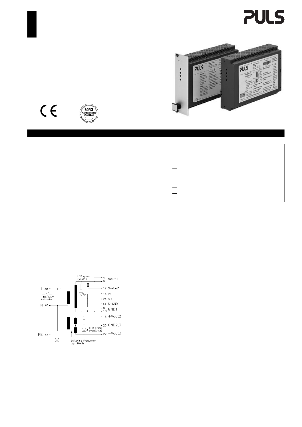
Schematic:
Vout [DC] Iout Pout Features Order-No.
Vout1
Max. total power: 120W
Vout1
Max. total power: 120W
"F" appended to Order No. means front panel 8 HP included and fitted.
Accessories: H15 connector, 6.3mm flat contacts:
Warranty: 2 years from date of delivery.
5V 14A
+12V 5A
2
–12V 5A
3
5V 14A
+15V 4A
2
–15V 4A
3
H15 connector with soldering pins:
70W ACin autoselect,
70W max.
70W ACin autoselect,
70W max.
AP377.111
PF, SD, OTP, OVP
AP377.121
PF, SD, OTP, OVP
ZP100
ZP120
Output
Voltage Vout1 adjustable min. ± 5% Trimmer1 on front panel.
Σ Vout2/3 adjustable min. ± 2% Trimmer2 on front panel.
Accuracy Vout1 max. ± 0.5% Includes production-adjustment,
Vout2/3 max. ± 3% line regulation, and load reg.
Sense lines Vout1 max. 0.25V Voltage compensation per line.
Vout2/3 None Not available.
Minimum load Vout1 None Not necessary.
Vout2 (12V/15V) max. 0.4A / 0.3A Function of current of Vout3.
Vout3 (12V/15V) max. 0.4A / 0.3A Function of current of Vout2.
Output power Pout max. 120W Total power.
Noise, Ripple Vout1, 2/3 max. 30mVpp, 50mVpp 20Hz...200kHz.
including spikes max. 50mVpp, 80mVpp 20Hz...20MHz.
Over-voltage protection typ. 6.3V Vout1, threshold accur. ± 3.5%.
Derating 3W/K +55° to +70°C Ta.
Operating indicator 2 green LED’s On the front, Vout1, Vout2+3.
Isolation Vout to Vin SELV EN 60 950, VDE 0805.
Vout1 to Vout2/3 200V AC
All outputs are protected against open-circuit, short-circuit, and overload.
Mechanical: 8HP / 3U board (DIN 41494) with totally
enclosed Al/Mg alloy cassette,
LxWxH = 171.93 x 40.64 x 112mm,
the length includes the connector, see page 4.
Weight: App. 770g
Connector: H15 (DIN 41612), coding option,
max. load per pin 11A @ 70° C.
Input
Line input AC 1 110...120V AC 115/230V autoselect.
Range 98...132V AC Full spec.
⋅
80...132V AC Derated, see page 2.
Line input AC 2 220...240V AC 115/230V autoselect.
Range 196...264V AC Full spec.
⋅
160...300V AC Derated, see page 2.
Line frequency 47...63Hz 400Hz, see page 2.
Input current rms max. 3.5Aeff. / 1.4Aeff. @ 115/230V AC.
Noise suppression EN 55 022/B 10kHz...30MHz, conducted.
Specifications are valid at 230V AC, unless otherwise stated. They are subject to change without prior
notice.
Page 2

AP377 ◆ 3 Outputs ◆ 19" Power Supply ◆ 120 Watt
AP377.111 AP377.121
Output
Voltage regulation
⋅
⋅
⋅
⋅
Ripple max. mVpp 30 50 30 50
⋅
Current limitation
⋅
⋅
⋅
⋅
Minimum load
⋅
⋅
Start delay t
Vout rise up time t
On and off characteristic
Input
AC input range 1 / 2 V AC 98...132 / 196...264
DC-input range V DC
Derated AC range 1 / 2 V AC 80...98 / 160...196, 300 for 0.5s
Frequency range Hz 47...63
Derated frequency range Hz 63...440
In-rush current max. A 25
Hold-up time min. ms 22
Power factor λ typ. 0.57
Internal fuse 5x20mm T5A/250V (IEC127/2-5)
Input range selection ACin autoselect
(continued)
5V ±12V 5V ±15V
Line regulation max. % ± 0.1 ± 0.3 ± 0.1 ± 0.3
Load regulation stat. ∆ U
Load regulation dyn. ∆ U
Response time t
max. % ±0.1 ± 3 ± 0.1 ± 3
stat
max. % ±10 ± 3 ± 10 ± 3
dyn
max. µs 500 500 500 500
s
Temperature coefficient typ. %/K ± 0.01 ± 0.01
incl. spikes max. mVpp 50 80 50 80
Threshold Vout1 min/max. A 105% ... 120% of Iout1
Threshold Vout2/3 min/max. W 73.5 ... 84 73.5 ... 84
Characteristics
Short-circuit Vout1 max. A 1.4 x Iout 1.4 x Iout
Short-circuit Vout2/3 max. A 1.8 x Iout 1.8 x Iout
Vout2 A — 0...0.4 — 0...0.3
Vout3 A — 0...0.4 — 0...0.3
Delay
Rise
typ. ms 400 400
typ. ms 10 10
(continued)
min. ms 24
98...132V AC / 196...264V AC, Iout = 100%.
Iout = 50%, ∆ Iout = ±50%, sense lines connected.
t
0
90%
10%
t
DelaytRise
100Hz
10%...90%...10% load change,
rise time dt = typ. 20µs.
Till ∆Vout is within < 0.5% of final value.
20Hz...200kHz, @ AC nom., Iout = 100%.
20Hz...20MHz, @ AC nom., Iout = 100%.
Fixed.
Fixed, total power.
Approximately constant current.
See graph on page 3.
Dependent on current at Vout3.
Dependent on current at Vout2.
After switch on.
Approximately monotonic.
Full spec.
Not admissible
Full spec.
Increased leakage currents.
No wait time for switch on / off.
NAMUR standard met.
@ 98V AC, Iout = 100%.
@ 196V AC, Iout = 100%, see graph on page 3.
@ 98V AC, Iout = 100%.
To replace, see page 4.
95%
Vout
Logic Functions
PF/PG-signal Power fail + Vout1 watch
PF/PG low 5ms before Vout1 < 4,75V
⋅
PF/PG high if ACin > 89/173V AC and Vout1 > 4,5V
⋅
Hold-up time
from power failure to PF-signal min. ms 16
⋅
from PF-signal min. ms 5
⋅
SD remote switch off Low-switch off
Vout adjustable min. % ± 5 ± 2 (Σ) ± 5 ± 2 (Σ)
Electromagnetic Compatibility
Emissions according to EN 80081-1
Radio interference, EN 55011, EN 55022
⋅
Immunity according to 50082-2
Electrostatic discharge ESD, EN 61000-4-2
⋅
Radiated fields, EN 61000-4-3
⋅
Fast transients, EN 61000-4-4
⋅
Surge transients, EN 61000-4-5
⋅
Transient voltage, IEC 255
⋅
NAMUR-prescription
⋅
Transient resistance, VDE 0160 §5.3.1.1.2
⋅
Over-voltage resistance (PULS standard)
⋅
Class B
8kV direct discharge (level 4)
15kV air discharge (level 4)
10V/m (level 3)
4kV (level 4)
2kV (level 3)
2kV (level 4) cap. coupling
4kV (isolation class 4)
2kV (isolation class 4)
5kV
Satisfied
750V / 1.3ms (class 2) 300V
AC / 0.5s
Open-collector (I
See graph on page 3, Iout = 100%.
@ 196V ACin.
See drawing on page 4.
Position for trimmer see on page 4.
EN 50081-2 is also satisfied
Conducted 10kHz...30MHz.
EN 50082-1 is also satisfied
To ACin, Vout and signal lines: length = 1m.
Coupled to ACin line.
Coupled to DCout line.
Coupled to Vout and signal lines.
Common mode, unit on.
Differential mode, unit on.
Common mode, unit off.
Valid for total load range.
= 5mA).
max
Page 3

p
3 Outputs ◆ 19" Power Supply ◆ 120 Watt ◆ AP377
Min. Hold-Up Time
170
150
130
110
90
70
Hold-Up Time [ms]
50
30
10
180 190 200 210 220 230 240 250 260 270
40% Load
60% Load
80% Load
100% Load
Outp ut Voltage Range 2 [Vac]
Typ. Voltage Deviation Full Load
3
2
1
0
Vout2,3 [%]
-1
-2
-3
0.2 0.4 0.6 0.8
0 0,2 0,4 0,6 0,8 1
less load
more l oad
Iout2,3/Iout3,2
Protection
Unit protection
Overload Yes See current limit.
⋅
Short-circuit proof Yes Auto voltage return.
⋅
Open-circuit proof Yes
⋅
Over-temp. (OTP) typ. +120° C Switch off.
⋅
on heatsink typ. +110° C Switch on (automatically).
Reverse battery prot. Yes
⋅
ACin range selection Auto select
⋅
Load protection
Over-voltage (OVP) Yes Switch off.
⋅
Threshold typ. 6.3V Valid for Vout 1.
Accuracy max. ± 3.5%
Method 15V Z-Diodes Vout 2/3, AP377.111.
18V Z-Diodes Vout 2/3, AP377.121.
Safety
Electrical safety
Test voltage (each unit) 3kV AC Primary / secondary.
⋅
according to EN 60 950 2.5kV AC Primary / PE.
for t = 2sec 500V AC Secondary / PE.
Air- and leakage distance 6.4 / 8mm Primary / secondary.
⋅
4mm Primary / PE.
Isolation resistance min. 5MΩ VDE 0551.
⋅
Protection class Ι VDE 0106 part 1, IEC 536.
⋅
PE resistance < 0.1Ω VDE 0805.
⋅
Protection system IP20 DIN 40050, IEC 529.
⋅
Leakage current max. 0.75mA EN 60 950 (47...63Hz line) .
⋅
Safe low voltage SELV EN 60 950, VDE 0805, VDE 0160.
⋅
Over voltage class ΙΙ VDE 0110 part 1, IEC 664.
⋅
Touch safety Finger test VDE 0100 §6, EN 60 950, VBG4.
Penetration protection > ∅ 3mm e.g. screws, small parts etc.
⋅
Typ. Derating over Temperature
130
120
110
100
90
80
70
60
50
40
Output Power Pout [W]
30
20
10
50 55 60 65 70 75
120 Wa t t
Temper atur e [ + ° C]
Typ. Efficiency
88
86
84
82
80
Efficiency [%]
78
76
74
20 40 60 80 100
Output Power [%]
230Vac
196Vac
Operation and Ambient Area
Application class KSF DIN 40040.
Operation temperature max. 0° ... +70°C Ta (measured at 1cm distance).
Derating range +55° ... +70°C Derating, see diagram.
⋅
Storage temperature typ. –20° ... +100°CTa.
Humidity max. 95% Non-condensing.
Mechanical usage Vertical See page 4.
Lateral spacing 1 HP To reach the specified values.
⋅
Cooling Normal convection Don’t obstruct air flow.
Dirt protection level max. 2 VDE 0110 part 1.
Vibration 0.075mm IEC 68-2-6 (10...60Hz).
Shock 11ms / 15g IEC 68-2-27 (3 shocks).
Operation Height max. 2,000m Above sea level.
Efficiency and Power Loss
AP377.111 and .121 typ. 86% / 20W @ 230V ACin, Iout = 100%.
Reliability and Lifetime
MTBF according to Siemens
standard SN29500 typ. 200,000h 230VAC, Iout = 100%, +40°C Ta.
Only long life (2,000h @ 105° C) electrolytic capacitors are used.
Function test
In-circuit test
Run-in (burn-in)
100% Test certificate enclosed.
Yes
24h Full load, Ta = +55° C,
on/off cycle.
T
his technical information is valid for +25° C ambient
erature and 5 minutes run in time, unless otherwise stated.
tem
Page 4

REGULATOR
Forward
concerter 5V
typ. 90 kHz
Controller
OVP
PF
Forward
converter
Vout2/3
typ. 90 kHz
Controller
A
B
A
B
VDE-Fade-out/
In-rush current limitation
Shutdown
115 / 230
REGULATO R
AP377 ◆ 3 Outputs ◆ 19" Power Supply ◆ 120 Watt
Do not
obstruct
air flow!
LED1 (Vout1)
LED2 (Vout2,3)
Trimmer 1 (Vout1)
Trimmer 2 (Vout2,3)
2)
1)
1)
3.0
2.5
4.0
(4x)
2.5
(2x)
3.0
Fuse
The PSU has electronic protection against external
short-circuits. In case of an internal defect, a fuse
disconnects the unit. It can only be replaced by
opening the unit which should be done by the
supplier.
Installation for Operating
The unit is constructed for 19" systems:
Ensure that pin 4 of H15 connector is on top. For
other installation considerations consult your
representative. Ensure free air flow.
Dimensions and Connections
19" board, with totally enclosed Al/Mg alloy cassette.
8HP plug in width. See figure below for dimensions.
1) Do not remove any screws on box, as internal safety
connections could be disconnected!
2) Vout1 adjustable at trimmer1 (min. ± 5%),
Σ
out2/3 adjustable at trimmer 2 (min. ± 2%).
V
Schematic
d
z
4
6
8
10
12
14
16
18
20
22
24
26
28
30
32
H15 pinout (DIN 41312)
NC = No Connection - Do not use!
Modifications (contact supplier)
Without ACin autoselect (230V range only).
Other output ranges.
Lower cost versions.
 Loading...