

Page 1
AP155
1 Output
◆
19" Power Supply, 96 to 120 Watt
◆ High efficiency: 88% (@ 24V)
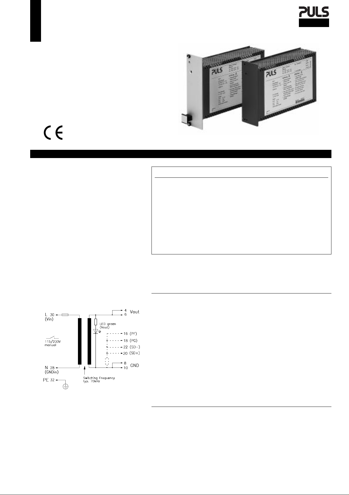
◆ ACin 115/230V manual switch
◆ 8 HP plug in width
◆ H15 standard pinout
◆ Parallel mode automatic load
sharing (@ AP155.133)
◆ Meets EMC standards
EN 50081-1 (EN 55022/B), EN 50082-2,
EN 61000-4, VDE 0160/2 and NAMUR
Data Sheet
AP155
This power supply is designed to m eet a wide ra nge of
applications. Output voltage is stab le with ripple and
noise below 60mVpp over the total range of up to
120W. The high-efficiency flyback converter provides
for greater reliability and economy.
Multiple supplies can be used in parallel to increase system power without extra control wiring, as the current is automatically shared between units (AP1 55.133
only).
The design ensures immunity to disturbances according to EN 61000-4, and VDE 0160 pulses (class 2 for
total range!). The unit is also protected against overvoltage and short-circuits. Construction and design
meet all relevant safety standards such as EN 60 950,
VDE 805 and VBG 804.
48V and 60V versions are available for telecommunica-
www.puls-power.de
tions and motor control applications.
See the web for current data sheet version:
Schematic:
Vout Iout Pout Features Order-No.
12V 8A
12V 8A
15V 7A
15V 7A
24V 5A
24V 5A
24V 5A
27.6V 4A
48V 2.5A
60V 2A
"F" appended to Order-No. means: 8HP front panel included and fitted.
Accessories: H15 connector, 6.3mm flat contacts:
Warranty: 2 years from date of delivery.
96W OVP
96W OVP, PF, PG, SD
105W OVP
105W OVP, PF, PG, SD
120W OVP
120W OVP, PF, PG, SD
120W OVP, parallel mode
110W OVP, Vout adjustable
120W OVP
120W OVP
H15 connector with soldering pins:
AP155.111
AP155.112
AP155.121
AP155.122
AP155.131
AP155.132
AP155.133
AP155.141
AP155.151
AP155.161
ZP100
ZP120
Output
Voltage Vout fixed All except AP155.141.
Vout adjustable min. ± 5% AP155.141.
Accuracy max. ± 2% Includes: production-adjustment,
AP155.133 max. ± 5% line regulation,
AP155.141 max. ± 0.5% and load regulation.
Sense lines None Not available.
Minimum load None Not necessary.
Output power Pout max. 120W Mounting side by side possible.
AP155.133 max. 96W Per unit @ parallel operation.
Noise, Ripple max. 60mVpp 20Hz...200kHz (@ 24V DC).
including spikes max. 80mVpp 20Hz...20MHz (@ 24V DC).
Over-voltage protection typ. 1.2 x Vout Threshold accuracy ± 4%.
Derating 2W/K +55°C to +70°C Ta.
Operating indicator 1 green LED On the front.
Isolation Vout to Vin SELV EN 60 950, VDE 0805.
The output is protected against open-circuit, short-circuit, and overload.
Mechanical: 8HP/3U board (DIN 41494),
Weight: App. 510g
Connector: H15 (DIN 41612), coding opti on,
PULS Munich
Tel.: +49 (0)89 / 92 78-2 44
/ AP155_
Page 1
Al/Mg alloy cover for component side,
plastic cover for bottom side,
LxWxH = 171.93 x 40.64 x 110mm (100),
the length includes the connector, see page 4.
max. load per pin 11A @70° C.
Arabellastraße 15
D- 81925 München
10.Mar.99
Fax: +49 (0)89 / 92 78-1 99
Input
Line input AC 1 100...120V AC Switch position 115V.
Range 88...132V AC Full spec.
⋅
80...150V AC Derated, see page 2.
Line input AC 2 220...240V AC Switch position 230V.
Range 187...264V AC Full spec.
⋅
150...300V AC Derated, see page 2.
Line frequency 47...63Hz DC or 400Hz, see page 2.
Input current rms. max. 3.0Aeff. / 1.4Aeff. @ 115/230V AC.
Noise suppression EN 55 022/B 10kHz...30MHz, conducted.
Specifications are valid at 230V AC, unless otherwise stated. They are subject to change without prior
notice.
Page 2

AP155
1 Output ◆ 19" Power Supply ◆ 96 to 120 Watt
.111 .131 .151
Output (continued) AP155. .122 .132 .133 .141 .161
Voltage regulation:
Line regulation max. %
⋅
Load regulation stat.
⋅
Load regulation dyn.
⋅
Response time t
Temperature coefficient typ. %/K
⋅
Ripple max. mVpp 25 25 25 25 60
incl. spikes max. mVpp 30 50 50 50 80
⋅
Current limitation
Threshold min/max. A 105% ... 120% of Iout
⋅
Characteristic See graph on page 3
⋅
Short-circuit max. A 220% of Iout
⋅
Start delay t
Vout rise-up time t
On and off characteristic
Power back immunity U
∆
U
max. %
stat
∆
U
max. %
dyn
max.
s
typ. ms 100
Delay
typ. ms 30
Rise
max. V 1.2 x Vout
Back
to
±
0.2± 0.2 ± 0.2 ± 0.2± 0.2
±
0.75± 0.75± 4.0± 0.75± 0.75
±
0.5± 0.5± 2.5 ± 0.5± 0.5
µ
s 800 800 1500 800 800
±
0.01± 0.01± 0.01± 0.01± 0.01
Input (continued)
AC input range 1 / 2 V AC 88...132 / 187...264
DC input range V DC 250...300
Derated AC range 1 / 2 V AC 80...88 / 150...187, 150 / 300 for 0.5s
Derated DC range V DC 176...250
V DC 300...370
Frequency range Hz 47...63
Derated frequency range Hz 63...400
In-rush current max. A 16
Hold-up time min. ms 23 20 20 22 20
min. ms 31 27 27 30 27
Power factor
Internal fuse 5x20mm T5A/250V
Input range selection Manual (230V AC set at factory)
λ
typ. 0.63
(IEC127/2-5)
88...132V AC / 187...264V AC, Iout = 100%.
Iout = 50%, ∆ Iout = ± 50%.
∆
Iout = 10%...90%...10%,
rise time dt = typ. 20µs.
Till ∆Vout is within < 0.5% of final value.
20Hz...200kHz, @ACnom, Iout = 100%.
20Hz...20MHz, @ACnom, Iout = 100%.
Fixed.
After switch on.
Approximately monotonic.
Unit off/on.
AP155.151 and .161 are not power back immune!
Full spec.
Full spec. (Voltage selector at ’230V’!)
Power loss typ. 10% (no start below 196V).
Full spec, but air- and leakage distances not longer than
stated in VDE 0805.
Full spec.
Increase leakage currents.
Wait min. 30s before switching on again (cold-start).
@88V AC, Iout = 100%.
@187V AC, Iout = 100%.
@88V AC, Iout = 100%.
To replace, see page 4.
115/230V AC switch, position see page 4.
95%
t
0
90%
10%
t
DelaytRise
100Hz
Vout
Logic Functions
Power Fail signal PF Power fail
PF high if ACin > 74/155V AC
⋅
Hold-up time
from Power failure to PF-signal min. ms 21 17 17 20 17
⋅
from PF-signal min. ms 5 5 5 5 5
⋅
PG-signal Output voltage within tolerance
PG high if 0.95 x Vnom
⋅
SD remote switch off Unit off
Parallel operation for AP155.133 units — —
Current distribution — —
⋅
Connection No additional wiring needed.
⋅
Vout adjustment for AP155.141 min. % — — —
Unilmited
Equal
——
——
±
5—
Electromagnetic Compatibility
Emissions according to EN 50081-1
Radio interference, EN 55011, EN 55022 Class B
⋅
Immunity according to EN 50082-2
Electrostatic discharge ESD, EN 61000-4-2 8kV direct discharge (level 4)
⋅
15kV air discharge (level 4)
Radiated fields, EN 61000-4-3 10V/m (level 3)
⋅
Fast transients, EN 61000-4-4 4kV (level 4)
⋅
2kV (level 3)
2kV (level 4) cap. coupling
Surge transients, EN 61000-4-5 4kV (Isolation class 4)
⋅
2kV (Isolation class 4)
Transient voltage, IEC 255 5kV
⋅
NAMUR-prescription Satisfied
⋅
Transient resistance, VDE 0160 §5.3.1.1.2 750V / 1.3ms (class 2)
⋅
Over-voltage resistance (PULS standard) 150/300V AC / 0.5s
⋅
PULS Munich
Tel.: +49 (0)89 / 92 78-2 44
/ AP155_
Page 2
10.Mar.99
Open-collector signal (I
@187V ACin, Iout = 100%, Vout ≥ 0.95 x Vrated.
SD+ and SD- connected.
No limit of number of AP155.133.
Characteristics see page 3.
Use equal-length output cables.
Position of trimmer see page 4.
EN 50081-2 is also satisfied
Conducted 10kHz...30MHz.
EN 50082-1 is also satisfied
To ACin, Vout and signal lines: length = 1m.
Coupled to ACin line.
Coupled to DCout line.
Coupled to Vout and signal lines.
Common mode, unit on.
Differential mode, unit on.
Common mode, unit off.
Valid for total load range.
Switch position 115 / 230V AC.
= 5mA), see figure page 3.
max
Page 3

1 Output ◆ 19" Power Supply ◆ 96 to 120 Watt
AP155
PF-Signal, PG-Signal and Hold-Up Time
Typ. Output Characteristics
125
100
75
50
Output Voltage Vout [%]
25
0
0 50 100 150
AP155
AP155.133
Output Current Iout [ %]
Typ. Derating over Temperature
130
120
110
100
90
80
70
60
50
Output Power Pout [W]
40
30
20
10
50 55 60 65 70 75
96 Watt
105 Watt
110 Watt
120 Watt
Temperature [+ °C]
Typ. Efficiency
88
86
Protection
Unit protection
Overload Yes See current limit.
⋅
Short-circuit proof Yes Auto restart.
⋅
Open-circuit proof Yes
⋅
Over-temperature (OTP) —
⋅
Reverse battery protect. Yes
⋅
ACin range selection Manual Switch for 115/2 30 V AC.
⋅
Load protection
Over-voltage (OVP) Yes
⋅
Threshold typ. 15.0V AP155.111, 112.
typ. 18.0V AP155.121, 122.
typ. 29.0V AP155.131, 132, 133.
typ. 32.0V AP155.141.
typ. 58.0V AP155.151.
typ. 70.0V AP155.161.
Accuracy max.± 4%
Restart After line disconnection; wait
time 1min.
Safety
Electrical safety
Test voltage 3kV AC Primary / secondary.
⋅
according to EN 60 950 2.5kV AC Primary / PE.
for t = 2sec 500V AC Secondary / PE.
Air- and leakage distance 6.4 / 8mm Primary / secondary.
⋅
4mm Primary / PE.
Isolation resistance min. 5M
⋅
Protection class
⋅
PE resistance < 0.1
⋅
Protection system IP20 DIN 40050, IEC 529.
⋅
Leakage current max. 0.75mA EN 60 950 (47...63Hz line) .
⋅
Safe low voltage SELV EN 60 950, VDE 0805, VDE 0160.
⋅
Over-voltage class
⋅
Ω
Ι
Ω
ΙΙ
VDE 0551.
VDE 0106 part 1, IEC 536 .
VDE 0805.
VDE 0110 part 1, IEC 664.
Touch safety Finger test VDE 0100 §6, EN 60 950, VBG4.
Penetration protection
⋅
> ∅
3mm e.g. screws, small parts etc.
Operation and Ambient Area
Application class KSF DIN 40040.
Operation temperature max. 0° ... +70°C Ta (measured at 1cm distance).
Derating range +55° ... +70°C Derating, see diagram.
⋅
Storage temperature typ. –20° ... +100°C Ta.
Humidity max. 95% Non-condensing.
Mechanical usage Vertical See page 4.
Lateral spacing None No gap needed.
⋅
Cooling Normal convection Don’t obstruct air flow.
Dirt protection level max. 2 VDE 0110 part 1.
Vibration 0.075mm IEC 68-2-6 (10...60Hz).
Shock 11ms / 15g IEC 68-2-27 (3 shocks).
Operation height max. 2,000m Above sea level.
Efficiency and Power Loss
AP155.111 and .112 typ. 86% / 15.6W @230V ACin, Iout = 100%.
AP155.121 and .122 typ. 86% / 17.0W As above.
AP155.131 to .133 typ. 88% / 16.4W As above.
AP155.141 typ. 88% / 15.1W As above.
AP155.151, 161 typ. 89% / 14.8W As above.
Efficiency [%]
84
82
20 40 60 80 100
Output Power [ %]
230Vac
110Vac
Reliability and Lifetime
MTBF according to Siemens
standard SN29500 typ. 300,000h 230VAC, Iout = 100%, +40°C Ta.
Only long life (>2,000h @105° C) electrolytic capacitors are used.
Function test 100% Test certificate enclosed.
In-circuit test Yes
Run-in (burn-in) 24h Full load, Ta = +55° C,
PULS Munich
Tel.: +49 (0)89 / 92 78-2 44
/ AP155_
Page 3
10.Mar.99
This technical information is valid for+25° C ambient
temperature and 5 min. run in time, unless otherwise stated.
on/off cycle.
Page 4

1)
Do not
obstruct
air flow!
2)
115/230V
Switch
Pin 4
LED green
(Vout)
3.5
2.5
(2x)
2.5
3.0
3.0
Additional module:
Powerfail
Powergood
Shutdown
Flyback
converter
typ.
70kHz
OVP
Regulator
F
I
L
T
E
R
AP155
1 Output ◆ 19" Power Supply ◆ 96 to 120 Watt
Fuse
The PSU has electronic protection against external
short-circuits. In case of an internal defect, a fuse
disconnects the unit. It can only be replaced by
opening the unit which should be done by the
supplier.
Installation for Operating
The unit is constructed for 19" systems:
Ensure that pin 4 of H15 connector is on top. For
other installation considerations consult your
representative. Ensure free air flow.
Important:
Use non-conductive (plastic) guide rails
only; conductive rails would inadmissibly reduce
leakage distance.
Dimensions and Connections
19" board, with Al/Mg alloy c over on co mpon ent side,
and a plastic cover on the bottom side. 8HP plug in
width. See figure below for dimensions.
1) Do not remove any screws on box, as internal safety
connections could be disconnected!
2) Vout adjustable at trimmer on AP155.141
(min. ± 5%).
Schematic
z
d
4
6
8
10
12
14
16
18
20
22
24
26
28
30
32
H15 pinout (DIN 41612)
NC = No Connection - Do not use!
Modifications (contact supplier)
Other output voltages.
Other DC input voltages.
Lower cost versions.
Important: With DCin, voltage selector must be in ’230V’ position!
Accessory ZP510
Installation set for mounting on DIN rail.
PULS Munich
Tel.: +49 (0)89 / 92 78-2 44
/ AP155_
Page 4
10.Mar.99
Arabellastraße 15
D- 81925 München
Fax: +49 (0)89 / 92 78-1 99
 Loading...