


Revision History
Revision Level Revision Date
Rev. A, ECO 539 May 1999
Rev. B, ECO 740 January 2000
Rev. C, ECO 818 August 2000
Rev. D, ECO 1149 May 2001
Rev. E, ECO 1532 May 2002
Rev. F, ECO 1983 April 2003
Rev. G, ECO 2374 September 2003
Rev. H, ECO 3580 November 2005
Rev. J, ECO 5019 December 2007
Rev. K, ECO 5407 July 2008
Contact Information
Pulmonetic Systems, Inc.
17400 Medina Rd., Suite 100
Minneapolis, Minnesota 55447-1341
Phone: (763) 398-8500
Office Fax: (763) 398-8400
Customer Care Center Phone: (800) 754-1914
Customer Care Center Fax: (763) 398-8403
Sales/Marketing E-mail: info@pulmonetic.com
Customer Care Center E-mail: service@pulmonetic.com
Pulmonetic Systems Website: http://www.pulmonetic.com
®
1000, LTV® 950, LTV® 900, LTV® 800 and LTV® are trademarks belonging to
LTV
Pulmonetic Systems, Inc.
©
Copyright
2008 Pulmonetic Systems, Inc., Minneapolis, Minnesota.
p/n 10665, Rev. K LTV® Series Ventilator Service Manual Page i

User/Owner Responsibility
This manual is intended for use only by service personnel who have been trained and
authorized by Pulmonetic Systems. Pulmonetic Systems does not condone or approve of
service activity on its products by untrained and unauthorized personnel. Pulmonetic
Systems is not responsible for any unauthorized repairs or any repairs made by
unauthorized procedures.
Use of an incorrect part or failure to exercise due care in the installation, removal, servicing,
checkout or calibration of parts and equipment may result in damage or malfunction of the
equipment. This may also result in damage to property and injury including death.
The purchaser and installer of these parts shall bear full responsibility and liability for the
above. All maintenance performed within the applicable warranty period must be authorized
in advance by a Pulmonetic Systems’ Service representative in order to retain the warranty
status of the subject unit.
Warranty
Pulmonetic Systems warrants that the LTV® Series ventilator is free from defects in material
and workmanship for a period of one (1) year from the date of shipment, or 8,800 hours as
measured on the usage meter, whichever comes first, with the following limitations:
Patient circuit components, including tubes, exhalation manifold, and other associated
parts are warranted for sixty (60) days from date of shipment.
The internal battery is warranted for ninety (90) days from date of shipment.
Pulmonetic Systems will, at its option, either repair, replace, or issue credit for products that
prove to be defective during the warranty period.
For warranty service or repair, the product must be returned to Pulmonetic Systems or a
service facility designated by Pulmonetic Systems, shipping prepaid by the Buyer.
LIMITATION OF WARRANTY
Ordinary maintenance, as specified in the LTV
®
Series or LTV® 800 Ventilator Operator’s
and Service Manuals, is not covered under the foregoing warranty
The foregoing warranty does not apply to defects resulting from:
1) Improper or inadequate maintenance of the unit;
2) Improper use or misuse of the unit;
3) Unauthorized modifications or repair to the unit;
4) Use of the unit with unauthorized accessories, e.g. external battery or AC adapter.
5) Operation of the unit outside the specified environment.
NO IMPLIED WARRANTIES
This warranty is exclusive. There are no other warranties expressed or implied.
LIMITATION OF LIABILITY
Pulmonetic Systems shall not be liable for loss of profits, loss of use consequential
damages, or any other claim based on breach of warranty. Pulmonetic Systems, Inc.’s
liability for damages of any kind shall be limited to the purchase price of the defective unit.
Page ii LTV® Series Ventilator Service Manual p/n 10665, Rev. K

Notices
The LTV® Series ventilator complies with limitations as specified in IEC 601-1-2 for Medical
Products. It does however, use and radiate radio frequency energy.
The function of this machine may be adversely affected by the operation of other nearby
equipment, such as high frequency surgical diathermy equipment, short-wave therapy
equipment, defibrillators or MRI equipment.
Notice to Users
Unsafe Operation - Servicing the LTV® Series ventilator without a complete and thorough
understanding of its attributes may result in unsafe operating conditions. It is important that
this manual be read and understood in its entirety before servicing the ventilator.
Warnings and Cautions Section - Read the section on Warnings and Cautions carefully
before attempting to service or operate the LTV® Series ventilators. General warnings and
cautions which apply any time you use the ventilator are listed in the front of this manual.
General and specific warnings and cautions also appear throughout the text where they are
most meaningful.
Use and Maintenance - Any questions regarding installing, setting up, operating, or
maintaining the LTV® Series ventilators, should be directed to a service technician who has
been trained and certified by Pulmonetic Systems or Pulmonetic Systems, Inc. using the
contact information at the front of this manual.
p/n 10665, Rev. K LTV® Series Ventilator Service Manual Page iii

Contents
Notices .........................................................................................................................................iii
Chapter 1 - Introduction.................................................................................. 1-1
Getting Assistance ....................................................................................................................1-1
Operator’s Safety Information ...................................................................................................1-2
Warnings ...................................................................................................................................1-3
Cautions ....................................................................................................................................1-4
Symbols.....................................................................................................................................1-6
Chapter 2 - Ventilator Checkout Tests .......................................................... 2-1
Alarm Test ................................................................................................................................. 2-4
Display Test...............................................................................................................................2-5
Control Test............................................................................................................................... 2-7
Leak Test...................................................................................................................................2-9
Vent Inop Alarm Test ..............................................................................................................2-11
Exit ..........................................................................................................................................2-12
Chapter 3 - Real Time Transducer Data ........................................................ 3-1
Chapter 4 - Cleaning and Sterilization........................................................... 4-1
Cleaning the Ventilator..............................................................................................................4-1
Cleaning the Exhalation Valve and Reusable Patient Circuit ...................................................4-2
Cleaning the Inlet Filter .............................................................................................................4-7
Cleaning the Fan Filter..............................................................................................................4-8
Chapter 5 - Preventative Maintenance........................................................... 5-1
Recommended Maintenance Schedule .................................................................................... 5-1
Before Initial Use.......................................................................................................................5-2
Storage Maintenance ................................................................................................................ 5-2
Daily Maintenance..................................................................................................................... 5-2
Monthly Maintenance ................................................................................................................ 5-2
10,000 Hour / 2 Year Maintenance ........................................................................................... 5-3
30,000 Hour Maintenance / 6 Year Maintenance .....................................................................5-3
Chapter 6 - Maintenance & Calibration.......................................................... 6-1
Operating Theory ......................................................................................................................6-1
Pneumatic Schematic Detail .................................................................................................6-3
Vent Maintenance .....................................................................................................................6-4
Vent Maintenance Entry........................................................................................................6-5
Vent Maintenance Entry Alarm .............................................................................................6-5
Calibration .................................................................................................................................6-6
Airway Pressure Calibration..................................................................................................6-7
Calibrate the Airway Pressure Transducers .........................................................................6-9
Flow Differential Calibration ................................................................................................6-11
Valve Differential Calibration............................................................................................... 6-14
O
Inlet Pressure Calibration............................................................................................... 6-17
2
Motor Drive Calibration .......................................................................................................6-19
Measure Turbine Speed (T/S).............................................................................................6-21
Vent Maintenance Exit ........................................................................................................6-23
Calibration Worksheet.........................................................................................................6-24
Flow Valve Calibration ............................................................................................................6-25
Flow Valve Calibration Worksheet ......................................................................................6-29
Servo ....................................................................................................................................... 6-30
Solenoid ..................................................................................................................................6-32
Step Test .................................................................................................................................6-33
Watchdog Test ........................................................................................................................6-34
Page iv LTV® Series Ventilator Service Manual p/n 10665, Rev. K

Configuration .......................................................................................................................... 6-35
Model Selection ...................................................................................................................... 6-36
Flow Valve Home Position...................................................................................................... 6-37
Temperature Compensation................................................................................................... 6-39
Analog Board Setting.............................................................................................................. 6-40
O
Blender .............................................................................................................................. 6-42
2
Configuration Menu Exit .........................................................................................................6-43
CLEAR.................................................................................................................................... 6-44
Vent Maintenance Menu Exit.................................................................................................. 6-45
Chapter 7 - Troubleshooting...........................................................................7-1
Displays and Buttons................................................................................................................ 7-2
Ventilator Performance............................................................................................................. 7-6
Advanced Vte Diagnostic Procedures .................................................................................... 7-22
Advanced FiO
Diagnostic Procedures .................................................................................. 7-26
2
Power and Battery Operation ................................................................................................. 7-28
Alarms..................................................................................................................................... 7-31
Checkout Test Failures........................................................................................................... 7-37
Test Lung Operation............................................................................................................... 7-41
Chapter 8 - Component Removal and Replacement.....................................8-1
Training and Authorization........................................................................................................ 8-1
Service Record ......................................................................................................................... 8-1
Tools ......................................................................................................................................... 8-2
Calling for Assistance ............................................................................................................... 8-2
Before removing the back panel............................................................................................... 8-3
Before replacing the back panel............................................................................................... 8-3
After performing any maintenance ........................................................................................... 8-3
Boots, Protective....................................................................................................................... 8-4
Boots, Temporary Removal.................................................................................................. 8-5
Boots, Permanent Removal.................................................................................................. 8-7
Boots, Reinstallation...........................................................................................................8-10
Boots, New Installation ....................................................................................................... 8-13
LTM/LTV mounting assembly installation and removal.......................................................... 8-16
LTM mounting assembly temporary removal (current LTMs) ............................................ 8-17
LTM mounting assembly permanent removal (current LTMs) ........................................... 8-18
LTM mounting assembly re-installation (current LTMs) .............................................. 8-18
LTM mounting assembly re-installation (current LTMs) .............................................. 8-19
LTM mounting assembly installation (current LTMs)................................................... 8-21
LTM/ LTV
LTM/LTV mounting bracket temporary removal (earlier model LTMs)............................... 8-25
LTM/LTV mounting bracket permanent removal (earlier model LTMs).............................. 8-26
LTM/LTV
LTM/LTV
Back Panel.............................................................................................................................. 8-31
Back Panel, Removal ......................................................................................................... 8-31
Dovetail Mounting Bracket, Replacement .......................................................................... 8-32
Back Panel, Reinstallation.................................................................................................. 8-35
Internal Flexible Tube Routing Configurations ....................................................................... 8-39
LTV
LTV
LTV
LTV
Alarm Sounder Assembly ....................................................................................................... 8-45
Analog Board Assembly ......................................................................................................... 8-48
External Inlet Filter.................................................................................................................. 8-51
Fan Assembly ......................................................................................................................... 8-52
Cleaning the Fan Filter ....................................................................................................... 8-54
®
mounting bracket (earlier model LTMs) ........................................................... 8-24
®
mounting bracket, reinstallation (for earlier model LTMs) ................................ 8-27
®
mounting bracket installation (earlier model LTM)............................................ 8-29
®
900, 950 and 1000 Current Version Tube Routing Diagrams................................... 8-40
®
900, 950 and 1000 Earlier Version Tube Routing Diagrams .................................... 8-42
®
800 Current and Earlier Tube Routing Diagram ....................................................... 8-43
®
800 Current and Earlier Tube Routing Diagram ....................................................... 8-44
p/n 10665, Rev. K LTV® Series Ventilator Service Manual Page v

Flow Valve Assembly and Cleaning Instructions ....................................................................8-55
Front Panel.............................................................................................................................. 8-64
Internal Battery Pack...............................................................................................................8-69
Internal Inlet Filter ...................................................................................................................8-72
Main Board Assembly .............................................................................................................8-73
Memory Board......................................................................................................................... 8-77
Checking the O2 Blender when upgrading software ..........................................................8-79
Motor Board Assembly............................................................................................................8-80
O2 Blender Assembly / O
O
Blender Filter......................................................................................................................8-89
2
O2 Blender Cap (LTV 1000 Only)........................................................................................... 8-90
O2 Port Cap (Low Pressure)...................................................................................................8-91
Power Board Assembly...........................................................................................................8-92
Right and Left Soft Side Panels ............................................................................................8-102
Rotary Switch (Set Value Knob) Assembly...........................................................................8-103
Solenoid Manifold Assembly................................................................................................. 8-105
Thermo Conductive Motor Board Heatsink Pad ...................................................................8-107
Thermo Conductive Turbine Pad ..........................................................................................8-108
Turbine Manifold ...................................................................................................................8-109
Inlet Block .....................................................................................8-82
2
Chapter 9 - Final Checkout Test..................................................................... 9-1
Checkout Test Selection ...........................................................................................................9-1
General Checkout .....................................................................................................................9-2
General Checkout Worksheet ............................................................................................... 9-8
Power Checkout......................................................................................................................9-12
Power Checkout Worksheet................................................................................................9-14
Performance Checkout ...........................................................................................................9-16
Performance Checkout Worksheet .....................................................................................9-25
24 Hour Burn-in.......................................................................................................................9-30
24 Hour Burn-in Worksheet.................................................................................................9-31
Appendix A - Ventilator Specifications .........................................................A-1
Appendix B - Glossary....................................................................................B-1
Appendix C - Service Record Form ...............................................................C-1
Appendix D - Event Trace...............................................................................D-1
Event Codes............................................................................................................................. D-3
Event Codes by Code # ....................................................................................................... D-3
Event Codes by Event Name ............................................................................................... D-6
Event Trace Data Definitions ............................................................................................... D-9
Appendix E - Reference Information .............................................................E-1
Conversion Factors .................................................................................................................. E-1
Extended Features Map...........................................................................................................E-2
Extended Features Map (continued)........................................................................................ E-3
External Accessories Screw Location, Type and Length......................................................... E-4
Input O
Parts, Replacement.................................................................................................................. E-8
Settings, Dip Switch ............................................................................................................... E-12
Settings, Front Panel Controls and Extended Features ........................................................ E-13
Tools, Required...................................................................................................................... E-14
Transducer Calibration, Acceptable A/D Counts ................................................................... E-15
Torque Values........................................................................................................................ E-16
Flow Chart.................................................................................................................. E-6
2
Appendix F - Index .......................................................................................... F-1
Page vi LTV® Series Ventilator Service Manual p/n 10665, Rev. K

Chapter 1 - I
This manual describes how to perform routine maintenance, troubleshooting, and repairs on
the LTV
trained and authorized by Pulmonetic Systems. Do not perform any of the procedures in
this manual unless you are trained and authorized for service on the LTV
®
Series ventilator. It is designed for use by service personnel who have been
NTRODUCTION
®
Series
ventilators.
This manual contains what you need to know to:
1) Perform preventative maintenance.
2) Calibrate the ventilator.
3) Perform routine troubleshooting.
4) Remove and replace major components of the ventilator.
®
See the LTV
Series or LTV® 800 Ventilator Operator's Manual for more information on
setting up and operating the ventilator.
Getting Assistance
If a problem occurs while maintaining the LTV® Series ventilator or if you require additional
information, contact a service technician who has been trained and certified by Pulmonetic
Systems or Pulmonetic Systems, Inc. at:
Pulmonetic Systems, Inc.
17400 Medina Rd., Suite 100
Minneapolis, Minnesota 55447-1341
Phone: (763) 398-8500
Office Fax: (763) 398-8400
Customer Care Center Phone: (800) 754-1914
Customer Care Center Fax: (763) 398-8403
Sales/Marketing E-mail: info@pulmonetic.com
Customer Care Center E-mail: service@pulmonetic.com
Pulmonetic Systems Website: http://www.pulmonetic.com
p/n 10665, Rev. K LTV® Series Ventilator Service Manual Page 1-1

Operator’s Safety Information
All Operators are to read and understand the following information about Warning, Caution
and Note statements before operating the LTV
®
Series ventilator.
General warnings and cautions which apply any time you use the ventilator are listed here.
General and specific warnings and cautions also appear throughout this manual where they
are most meaningful.
WARNING
“Warning” statements contain information about circumstances or practices that may cause
serious and undesirable results, or expose the patient or operator to danger.
CAUTION
“Caution” statements contain information about circumstances or practices that may result
in equipment damage.
Note
“Note” statements contain additional information to assist in the proper operation of the
LTV® Series ventilators.
Page 1-2 LTV® Series Ventilator Service Manual p/n 10665, Rev. K

Warnings
WARNING
WARNING
Ventilator Service and Repair - Only service technicians who have been trained and
certified by Pulmonetic Systems, Inc. are authorized to perform repairs or maintenance on
the LTV® series ventilators. Do not attempt to repair or replace any part of the ventilator
unless you are trained and certified to do so by Pulmonetic Systems. Personal injury could
result.
Fire or Explosion - Operation of the LTV® Series ventilators in the presence of flammable
gases could cause a fire or explosion. Under no circumstances is the ventilator to be
operated when explosive gases are present. The presence of nitrous oxide or flammable
anesthetics presents a danger to the patient and operator.
Untrained Personnel – Only properly trained personnel should operate the ventilator. The
LTV® Series ventilator is a restricted medical device designed for use by Respiratory
Therapists or other properly trained and qualified personnel under the direction of a
physician and in accordance with applicable state laws and regulations.
Unauthorized Parts or Accessories – Serious harm to the patient may result from the use
of unauthorized parts or accessories. Only items expressly approved by Pulmonetic
Systems may be used in conjunction with the LTV® Series ventilators.
Ventilator Checkout Tests – Be aware that gas is not delivered to the patient during these
tests. Disconnect the patient from the ventilator and ventilate the patient using an alternative
method before running the Ventilator Checkout tests.
Ventilator Checkout and Maintenance Modes - The LTV® Series ventilator does not
deliver gas during the Ventilator Checkout mode (VENT CHECK) or Ventilator Maintenance
mode (VENT MTNCE) and should not be used to ventilate a patient during these tests.
Mounting Screw Use – Internal damage to the ventilator may result if wrong length
mounting screws are used to secure parts or accessories. Refer to the information
contained in Replacement Screws Kit, P/N 11149, to determine the appropriate accessories
mounting screws or accessories replacement screws to use when removing or exchanging
external accessories on an LTV® Series ventilator.
Patient Circuits – Pulmonetic Systems Patient Circuits, Exhalation Valve Assemblies and
Water Traps are shipped clean, not sterile.
Ultra Violet Light Sensitivity – The material used in the tubing of the “Reusable” Patient
Circuits is not UV stable. Avoid exposure of tubing to UV light.
PEEP Valve Rotation – Attempting to adjust the PEEP valve counterclockwise past zero (0)
may damage the PEEP valve assembly and cause circuit leaks.
To avoid damaging the PEEP valve, always depress the yellow lock button on top of the
valve when making adjustments.
p/n 10665, Rev. K LTV® Series Ventilator Service Manual Page 1-3

Cautions
CAUTION
Electrical Grounding – In the event of a loss of electrical protective ground, touching the
ventilator could result in electrical shock. To ensure grounding and avoid this danger, use
only the unmodified power cord originally supplied with the LTV® Series ventilators,
maintained in good condition and connected to a properly wired and grounded electrical
power outlet.
Fuse Fire Hazard – Replacement of existing fuses with fuses with different voltage or
electrical current ratings may cause a fire.
Storage Temperature - Storing the LTV® Series ventilator at temperatures above 60°C
(140°F) for long periods can damage the internal battery and cause expected battery
duration to degrade.
Patient Assist Call Connector – Do not apply more than 25V rms or 32VDC to the Patient
Assist Call connector.
CLEAR Function Cautions - The CLEAR function should be used with great care as once
a section of the memory is cleared, all data in that section of memory is lost and it cannot be
automatically restored.
Electronic and Mechanical Parts - The LTV® Series ventilator contains delicate electronic
and mechanical parts that must be handled properly to avoid damage. Follow the
instructions given in this manual carefully and make sure to observe all instructions.
Opening the ventilator - Always turn the ventilator OFF and remove the external power
before opening the ventilator case or attempting to service the ventilator.
Anti-static Precautions - Always wear a grounded anti-static wrist strap when handling the
ventilator with the case open. Electrostatic discharge can damage the internal electronics.
Verification of Operation - After opening the ventilator and performing any maintenance,
verify proper operation of the ventilator by performing the checks and calibrations
recommended in Chapter 9 - Final Checkout Test.
Ventilator Sterilization – To avoid irreparable damage to the LTV® Series ventilator, do not
attempt to sterilize it.
Cleaning Agents – To avoid damaging the ventilator’s plastic components and Front Panel,
do not use cleaning agents containing ammonium chloride, other chloride compounds, more
than 2% glutaraldehyde, phenols, or abrasive cleaners.
Page 1-4 LTV® Series Ventilator Service Manual p/n 10665, Rev. K

CAUTION
Ventilator Immersion - Do not immerse the ventilator in liquids.
High pressure air nozzle – Only a low-pressure air nozzle with flow less than 10 liters per
minute should be used around the ventilator. High pressure can damage the ventilator, in
particular the differential pressure ports.
Exhalation Valve - Do not pour or spray liquids into the exhalation valve.
Patient Wye Installation – Always install the patient wye in the patient circuit so the
proximal sense lines are oriented up while operating.
Front Panel – Do not pour or spray liquids onto the Front Panel.
Care of Bacterial Filters – If bacterial filters are used in conjunction with the LTV® Series
ventilator, comply with all recommended care procedures as specified by the filter
manufacturer.
Wet or Damp Filters - Do not install any wet or damp filters into the LTV® Series ventilators.
This could damage the ventilator.
Proximal Sense Lines - Do not remove the proximal sense lines from the patient wye.
Software Caution – Never install a version of software lower than the version originally
installed in the ventilator. Erroneous operation may result from the installation of an
incompatible software version. Generally, LTV® ventilator software is designed to be
backwards-compatible with this exception.
p/n 10665, Rev. K LTV® Series Ventilator Service Manual Page 1-5
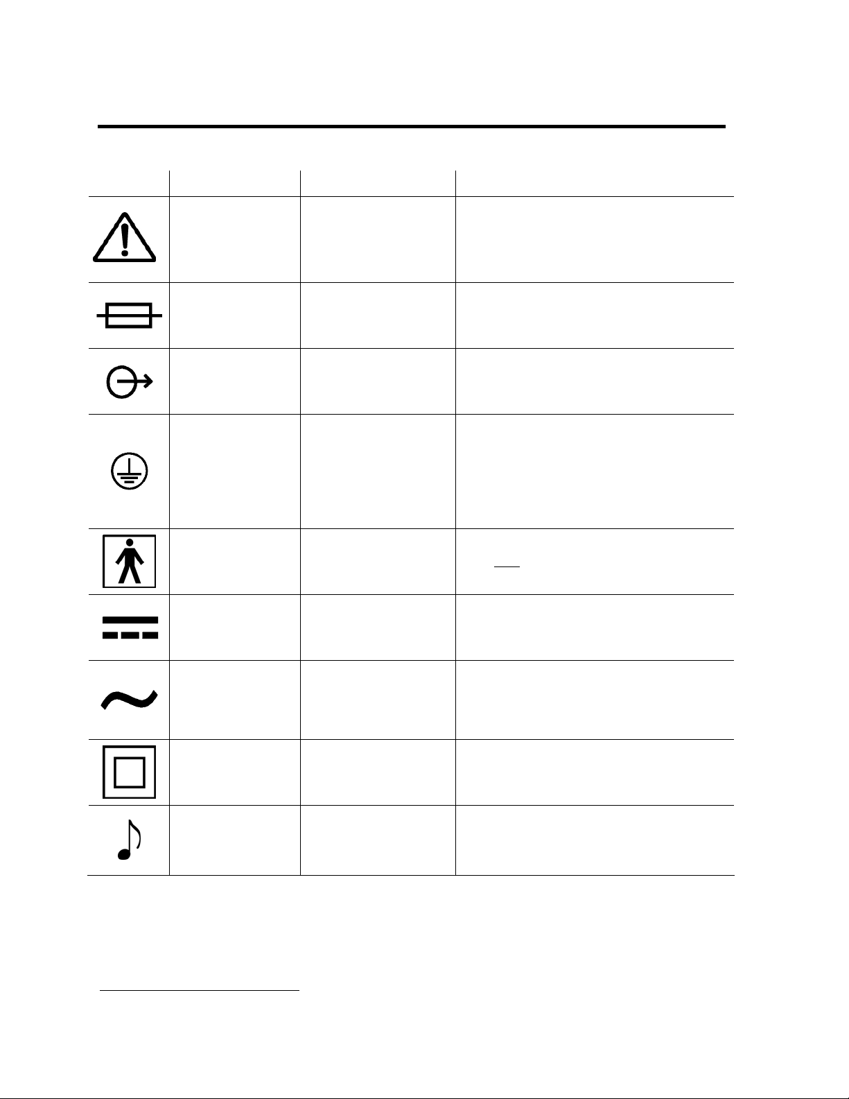
Symbols
Symbol
Compliance
ISO 3864
(Prev. IEC 348)
Symbol No.
B.3.1
1
Caution (refer to
accompanying
documents)
Title Application
Direct the user to the instruction
manual where it is necessary to follow
certain specified instructions where
safety is involved.
IEC 417
Symbol No. 417-
IEC-5016
IEC 417
Symbol No. 417-
IEC-5035
IEC 417
Symbol No. 417-
IEC-5019
IEC 417
Symbol No. 417-
IEC-5333
IEC 417
Symbol No. 417-
IEC-5031
IEC 417
Symbol No. 417-
IEC-5032
Fuse Indicates the location of fuses.
Output Identifies an output terminal when it is
necessary to distinguish between
inputs and outputs.
Protective earth
(ground)
To identify any terminal which is
intended for connection to an external
protective conductor for protection
against electric shock in case of a fault
or the terminal of a protective earth
(ground) electrode.
Type BF equipment. To mark type BF equipment complying
with IEC
Publication 601.
Direct Current Indicates on the rating plate that the
equipment is suitable for direct current
only; to identify relevant terminals.
Alternating current Indicates on the rating plate that the
equipment is suitable for alternating
current only; identifies relevant
terminals.
Class II equipment To identify equipment meeting safety
requirements specified for Class II
equipment.
Sound; audio Identifies controls or terminals related
to audio signals.
Symbol No. 417-
IEC-5172
IEC 60417
Symbol No.
IEC 417
5182
1
Reference IEC Medical Electrical Equipment, 2nd. Edition 1988
Page 1-6 LTV® Series Ventilator Service Manual p/n 10665, Rev. K

Chapter 2 - V
This chapter details five test procedures that are initiated through the Vent Check menu and
used to verify the proper operation of the LTV
ENTILATOR CHECKOUT TESTS
®
Series ventilator. These Checkout Tests are
to be performed before using the ventilator on a patient and in accordance with
recommended periodic maintenance and testing of the ventilator. See Chapter 5 -
Preventative Maintenance.
The five test procedures are:
Test Test used to:
Alarm Test Verify that the audible alarm is working correctly.
Display Test Verify that the ventilator displays are working correctly.
Control Test Verify that the ventilator buttons and the Set Value knob are
working correctly.
Leak Test Test the patient circuit for leaks.
Vent Inop Alarm Test Verify that the Inop alarm is working correctly.
The Vent Check Menu is set up as follows:
VENT CHECK
ALARM
DISPLAY
CONTROL
LEAK
EXIT
WARNING
Ventilator Checkout and Maintenance Modes - The LTV® Series ventilator does not
deliver gas during the Ventilator Checkout mode (VENT CHECK) or Ventilator Maintenance
mode (VENT MTNCE) and should not be used to ventilate a patient during these tests.
p/n 10665, Rev. K LTV® Series Ventilator Service Manual Page 2-1
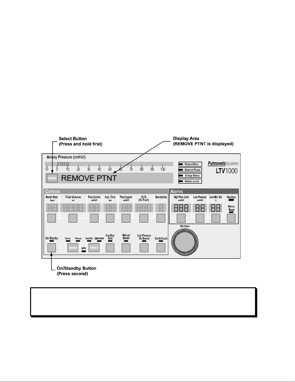
To enable the Ventilator Checkout menu:
To enter the Ventilator Checkout (VENT CHECK) menu, a special power on sequence is
required.
1) Disconnect the patient from the ventilator and ventilate using an alternative method.
2) With the ventilator off, connect the AC Adapter to the ventilator and plug it in to a valid
AC power source. Verify that the External Power and Charge Status LEDs are
illuminated or flashing.
3) Press and hold down the Select button. While holding the Select button, press the
On/Standby button to turn the ventilator on.
• REMOVE PTNT is displayed; if it does not display, repeat steps 2 through 4.
• An audible alarm (alternating on/off tone) will sound while REMOVE PTNT is
displayed.
Note
Although the LTV® 1000 Front Panel is shown, the test is applicable to all LTV® Series
ventilators.
Page 2-2 LTV® Series Ventilator Service Manual p/n 10665, Rev. K

4) Clear the alarm by pressing the Silence/Reset button.
• The audible alarm silences, and the display changes from REMOVE PTNT to
VENT CHECK.
To enter the Ventilator Checkout menu:
1) Push the Select button.
2) The first Ventilator Checkout Test, ALARM is displayed.
Note
Although the LTV® 1000 Front Panel is shown, the test is applicable to all LTV® Series
ventilators.
p/n 10665, Rev. K LTV® Series Ventilator Service Manual Page 2-3

Alarm Test
The alarm test verifies that the audible alarm is working correctly.
To run the alarm test:
1) Press the Select button while ALARM is displayed.
2) Verify that the audible alarm is sounded.
3) When the alarm has sounded for at least 2 seconds, push the Select button again.
• The audible alarm is silenced and the next menu item is displayed.
4) Verify a confirming audible chirp occurs after the alarm is silenced.
Note
Although the LTV® 1000 Front Panel is shown, the test is applicable to all LTV® Series
ventilators.
If the ventilator fails the alarm test, see Chapter 7 - Troubleshooting for more information.
Page 2-4 LTV® Series Ventilator Service Manual p/n 10665, Rev. K

Display Test
At the end of the Alarm test, DISPLAY shows in the LED display window. The display test
verifies that the ventilator displays are working correctly.
To run the Display Test:
1) Press the Select button while DISPLAY is showing.
2) All segments of the 7-segment control displays; all dots of the dot-matrix window
displays and all LEDs are illuminated.
Note
Although the LTV® 1000 Front Panel is shown, the test is applicable to all LTV® Series
ventilators.
3) To end the display test, press the Select button again and the next menu item is
displayed.
Note
The displays for the External Power, Vent Inop, and Charge Status LEDs are not tested
by the Display Test.
• The External Power and Charge Status LEDs are tested when the AC adapter is
connected to the ventilator (see page 2-2).
• The Vent Inop LED is tested during the Vent Inop alarm test (see page 2-2).
p/n 10665, Rev. K LTV® Series Ventilator Service Manual Page 2-5

Displays will be illuminated in the following colors:
Display Color Display Color
Airway Pressure Display Green
Pressure Mode LED
Display Window Red Assist/Control Mode LED Green
Breath Rate Green SIMV/CPAP Mode LED Green
Tidal Volume Green NPPV Mode LED Green
Pressure Control2 Green
Inspiratory / Expiratory Hold LED
Inspiratory Time Green Manual Breath LED Green
Pressure Support Green
Low Pressure O
Source LED3
2
O2 %3 Green Control Lock LED Green
Sensitivity Green Patient Effort LED Green
High Pressure Limit alarm Red External Power LED Not tested
Low Pressure alarm Red Charge Status LED Not tested
Low Minute Volume alarm Red Battery Level LED Amber
On/Standby LED Green Vent Inop LED Not tested
Volume Mode LED3
Green Silence Reset LED Red
2
3
Green
Green
Green
If the ventilator fails the Display Test, see Chapter 7 - Troubleshooting for more information.
2
Not applicable to the LTV® 900 or 800
3
Applicable to the LTV® 1000 only
Page 2-6 LTV® Series Ventilator Service Manual p/n 10665, Rev. K

Control Test
At the end of the Display test, CONTROL shows in the LED display window. The Control
Test is used to verify that the ventilator buttons and the Set Values knob are working
correctly.
To run the Control Test:
1) Press the Select button while CONTROL is displayed.
2) SELECT is displayed in the display window.
p/n 10665, Rev. K LTV® Series Ventilator Service Manual Page 2-7

Note
Although the LTV® 1000 Front Panel is shown, the test is applicable to all LTV® Series
ventilators.
3) Test each control by pressing every button, one at a time. When each one is pressed,
verify that the name of the button is displayed in the display window.
Control names are as shown in the table below:
Control Display
Display Select
Breath Rate
Tidal Volume
Pressure Control4
Inspiratory Time
Pressure Support
O2 %5
Sensitivity
High Pressure Alarm
Low Peak Pressure
Low Minute Volume
Silence / Reset
On/Standby
Volume & Pressure4
Assist/Control & SIMV/CPAP
Inspiratory / Expiratory Hold5
Manual Breath
SELECT
BREATH RATE
TIDAL VOLUME
PRES CONTROL
INSP TIME
PRES SUPPORT
O2%
SENSITIVITY
HIGH PRES
LOW PRES
LOW MIN VOL
SILENCE
ON / STNDBY
MODE VOL/PRS
MODE A/C S/C
IE HOLD
MANUAL BRTH
Low Pressure O2 Source5
Control Lock
Set Value Knob rotate Left
Set Value Knob rotate Right
LOW PRES O2
CONTROL LOCK
ROTATE LEFT
ROTATE RIGHT
4) Test the Set Value knob by turning it clockwise and counterclockwise. Verify that the
direction of rotation is displayed in the display window.
5) To exit the control test, press the Select button again and the next menu item is
displayed.
If the ventilator fails the Control Test, see Chapter 7 - Troubleshooting for more information.
4
Not applicable to the LTV® 800 and 900
5
LTV 1000 only
Page 2-8 LTV® Series Ventilator Service Manual p/n 10665, Rev. K

Leak Test
The Leak test is used to test the patient circuit for leaks.
To run the Leak Test:
1) At the end of the Control test, LEAK shows in the LED Display window.
2) Attach all patient circuit accessories (such as water traps, heated circuits and humidifiers
to the patient circuit.
®
3) Connect the patient circuit to the LTV
4) With a clean, gloved hand or 4”X4” gauze pad, occlude the proximal end of the patient
circuit.
Series ventilator.
5) Press the Select button while
LEAK is displayed.
Note
The Leak Test cannot be run until the ventilator has been running for 60 seconds. If you
attempt to run the leak test before the warm-up period has completed, a WAITING message
will be displayed. When the warm-up period is complete, the Leak Test menu item is
redisplayed.
p/n 10665, Rev. K LTV® Series Ventilator Service Manual Page 2-9

6) To perform the Leak Test, the ventilator does the following:
a) Closes the exhalation valve and sets the flow valve to a near-closed state. The
display briefly shows HOMING VALVE.
b) Elevates the turbine motor speed. The display shows SET TURBINE.
c) Elevates the circuit pressure. The display shows PRES xx.x cmH
the real-time airway pressure.
d) Sets the flow valve to a near closed position. The display shows FLOW xx.x Lpm
where xx.x is the flow through the flow valve.
e) After several seconds, the display shows
indicating the Leak Test results.
7) The Leak Test will fail if the flow through the flow valve is equal to or greater than 1.0
Lpm.
8) To exit the Leak Test, press the Select button again and the next menu item is
displayed.
LEAK xx.xx PASS or LEAK xx.xx FAIL
O where xx.x is
2
Note
Although the LTV® 1000 Front Panel is shown, the test is applicable to all LTV® Series
ventilators.
If the ventilator fails the Leak Test, see Chapter 7 - Troubleshooting for more information.
Page 2-10 LTV® Series Ventilator Service Manual p/n 10665, Rev. K

Vent Inop Alarm Test
The Vent Inop alarm test is used to verify that the Inop alarm is working correctly.
To run the Vent Inop alarm test:
1) To run the Vent Inop alarm test, the ventilator must be on (running) for at least 60
seconds.
2) Turn the ventilator off by pressing and holding the On/Standby button for a minimum of
3 seconds. DO
NOT press the Silence/Reset button.
3) Observe the ventilator for 15 seconds and verify that both
• The alarm tone sounds continuously for a full 15 seconds.
• The Vent Inop LED illuminates continuously for a full 15 seconds.
of the following occur;
4) Silence the alarm by pressing the Silence/Reset button.
5) Verify a confirming audible chirp occurs after the alarm is silenced.
Note
Although the LTV® 1000 Front Panel is shown, the test is applicable to all LTV® Series
ventilators.
If the ventilator fails the Vent Inop alarm test, see Chapter 7 - Troubleshooting for more
information.
p/n 10665, Rev. K LTV® Series Ventilator Service Manual Page 2-11

Exit
To exit VENT CHECK and enter normal ventilation mode:
1) Turn the Set Value Knob to scroll through the main menu entries (VENT OP, ALARM
OP, VENT CHECK, etc.) until EXIT is displayed.
2) Push the Select button while EXIT is displayed.
3) Alternatively, push the Control Lock button until normal ventilation mode is restored.
POST will be performed and the ventilator will begin ventilation using the previously stored
settings.
Page 2-12 LTV® Series Ventilator Service Manual p/n 10665, Rev. K

Chapter 3 - R
EAL TIME TRANSDUCER DATA
The Real Time Transducer data allows you to view the real time activity in the ventilator. The
real time transducer menu is set up as follows:
RT XDCR DATA
AP xx.xx
FDb xx.xx
FDw xx.xx
FDn xx.xx
FTw or FTn
xx.xx Lpm
FTb x.xx Lpm
LEAK xx.xx Lpm
FVd xx.xx
c
c
c
c
c
H20
m
H20
m
H20
m
H20
m
H20
m
(Not on LTV
(Not on LTV
(Not on LTV
®
800)
®
800)
®
800)
(Not on LTV® 800)
(Not on LTV
(Not on LTV
®
800)
®
800)
FV xx.xx Lpm
®
FVt xxx.x °F
Optional (Not on LTV
800)
STEP xxxx
TS xxxx rpm
®
(LTV
O2 xx.xx PSIG
1000 only)
BV xx.xx VOLTS
EV xx.xx VOLTS
RT EXIT
Each item displays real time activity in the displayed units. For some items, transducer
counts can also be displayed. Pressing Select while the item is displayed, displays
additional transducer data.
Display Real Time Data
AP xx.xx
c
H20
m
Airway pressure as measured at the patient wye using the high
side proximal sense line.
FDb xx.xx
(Not on LTV
FDw xx.xx
(Not on LTV
c
c
H20
m
m
®
800)
H20
®
800)
p/n 10665, Rev. K LTV® Series Ventilator Service Manual Page 3-1
Flow differential pressure as measured at the patient wye using
the bi-directional transducer. Differential pressure is measured
between the high and low side proximal sense lines.
Flow differential pressure as measured at the patient wye using
the wide scale transducer. Differential pressure is measured
between the high and low side proximal sense lines.

Display Real Time Data
FDn xx.xx
(Not on LTV
c
m
H20
®
800)
Flow differential pressure as measured at the patient wye using
the narrow scale transducer. Differential pressure is measured
between the high and low side proximal sense lines. The
narrow scale transducer is only used for differential pressures
between -0.35 cmH
Lpm to 15 Lpm).
O and 0.35 cmH2O (approximately -15
2
FTw xx.xx Lpm
or
FTn xx.xx Lpm
(Not on LTV
®
800)
FTb x.xx Lpm
®
(Not on LTV
800)
LEAK xx.xx Lpm
c
m
®
800)
H20
(Not on LTV
FVd xx.xx
FV xx.xx Lpm
FVt xxx.x °F
(Not on LTV
®
800)
Flow in Lpm calculated from the differential pressure measured
at the patient wye. When the value is calculated using the wide
scale differential pressure, FTw is displayed. When the value is
calculated using the narrow scale differential pressure, FTn is
displayed.
When Leak Compensation is on, FTw xx.xx and FTn xx.xx
Lpm values are offset by the value of LEAK xx.xx Lpm.
Transducer count display is not available for this item.
Flow in Lpm calculated from the differential pressure measured
at the patient wye using the bi-directional transducer.
Transducer count display is not available for this item.
Leak flow calculated from the differential pressure transducer,
measured at the patient wye during exhalation.
Differential pressure as measured across the flow valve.
Flow valve flow in Lpm calculated from the differential pressure
measured across the flow valve.
Transducer count display is not available for this item.
Flow valve temperature. Only available on the LTV 900, 950
and 1000 with FVt capability. Not available on the LTV 800.
STEP xxxx
Commanded flow valve motor step position.
Transducer count display is not available for this item.
TS xxxx rpm
O2 xx.xx PSIG
®
(LTV
1000 only)
BV xx.xx VOLTS
EV xx.xx VOLTS
Monitored turbine speed in rpms.
Oxygen inlet pressure in PSIG as measured at the inlet
pressure transducer.
Internal battery voltage.
External power voltage.
Page 3-2 LTV® Series Ventilator Service Manual p/n 10665, Rev. K

Chapter 4 - C
LEANING AND STERILIZATION
Cleaning the Ventilator
All ventilator external surfaces should be cleaned before and after each patient use, and as
may be required.
To clean the ventilator:
1) Wipe the exterior surfaces of the ventilator with a clean, damp cloth. The use of an anti-
bacterial cleaning solution is recommended. Be sure to wipe away any residual cleaner.
CAUTION
Ventilator Sterilization – To avoid irreparable damage to the LTV® Series ventilator, do not
attempt to sterilize it.
Cleaning Agents – To avoid damaging the ventilator’s plastic components and Front Panel,
do not use cleaning agents containing ammonium chloride, other chloride compounds, more
than 2% glutaraldehyde, phenols, or abrasive cleaners.
Ventilator Immersion - Do not immerse the ventilator in liquids.
Exhalation Valve Cleaning - Do not pour or spray liquid cleaners into the exhalation valve.
Front Panel Cleaning – Do not pour or spray liquid cleaners onto the Front Panel.
p/n 10665, Rev. K LTV® Series Ventilator Service Manual Page 4-1

Cleaning the Exhalation Valve and Reusable Patient Circuit
WARNING
Patient Circuits – Pulmonetic Systems Patient Circuits, Exhalation Valve Assemblies and
Water Traps are shipped clean, not sterile.
Ultra Violet Light Sensitivity – The material used in the tubing of the “Reusable” Patient
Circuits is not UV stable. Avoid exposure of tubing to UV light.
PEEP Valve Rotation – Attempting to adjust the PEEP valve counterclockwise past zero (0)
may damage the PEEP valve assembly or cause circuit leaks. To avoid damaging the PEEP
valve, always depress the yellow lock button on top of the valve when making adjustments.
CAUTION
Proximal Sense Lines - Do not remove the proximal sense lines from the patient wye.
Care of the Exhalation Valve - The exhalation valve is a delicate assembly and may be
damaged if;
• Care is not exercised when handling or cleaning it.
• Cleaning instruments or foreign bodies are inserted into it.
• High-pressure gas nozzles are used to dry it.
Care of Bacterial Filters – If bacterial filters are used in conjunction with the LTV® Series
ventilator, comply with all cleaning procedures as specified by the filter manufacturer.
To clean the exhalation valve, wye, sense line(s) and reusable patient circuit:
For purposes of cleaning, the patient circuit with exhalation valve and all accessories must
be detached from the ventilator.
1) Disassemble the exhalation valve as shown (on following pages) and remove the
diaphragm and compression spring. If using a patient circuit with a PEEP valve; remove
the exhalation valve retainer collar (rotate) and pull the PEEP valve assembly off the
exhalation valve body. USE CAUTION: The diaphragm and spring may become
dislodged.
2) Remove exhalation valve diaphragm and compression spring.
Page 4-2 LTV® Series Ventilator Service Manual p/n 10665, Rev. K

LTV® 900, 950 and 1000 Reusable Patient Circuits:
p/n 10665, Rev. K LTV® Series Ventilator Service Manual Page 4-3

LTV® 800 Reusable Patient Circuits:
Page 4-4 LTV® Series Ventilator Service Manual p/n 10665, Rev. K
 Loading...