


OWNER’S MANUAL
#2700 (16K) Industry Standard
SuperGlide
Gross Trailer Weight (Maximum) 16,000 lbs.
Vertical Load Weight (Max. Pin Weight) 4,000 lbs.
#2300 (24K) Industry Standard
Gross Trailer Weight (Maximum) 24,000 lbs.
Vertical Load Weight (Max. Pin Weight) 6,000 lbs.
#2900 (18K) Industry Standard
SuperGlide
Gross Trailer Weight (Maximum) 18,000 lbs.
Vertical Load Weight (Max. Pin Weight) 4,500 lbs.
SuperGlide
The following instructions provide valuable information regarding the function and proper
use of the SuperGlide Fifth Wheel Towing System.
YOU MUST COMPLETELY READ THE INSTRUCTIONS WITHIN THIS MANUAL, PRIOR TO OPERATING THE HITCH
TO PREVENT UNNECESSARY DAMAGE TO THE HITCH, VEHICLE, OR TRAILER.
For more information, please call PullRite at (800) 443-2307.
1.3.17:revD3a

TABLE OF CONTENTS
SYSTEM WEIGHT RATING vs. COMPONENT WEIGHT RATING .....................................................................................1
HOW DOES THE SUPERGLIDE WORK? .............................................................................................................................2
CAUTION ...............................................................................................................................................................................3
TESTING CLEARANCE ......................................................................................................................................................... 3
BASE RAIL FOOT ASSEMBLY ..............................................................................................................................................4
INSTALLING THE BASE RAIL FEET ............................................................................................................................. 4
LUBRICATION ........................................................................................................................................................................ 6
MAINTENANCE .............................................................................................................................................................6
HITCH LUBRICATION....................................................................................................................................................6
FIFTH WHEEL PLATE & KING PIN ...............................................................................................................................7
FIFTH WHEEL PLATE OPERATION ......................................................................................................................................8
HITCHING ............................................................................................................................................................................10
SAFETY CHECKS ................................................................................................................................................................ 11
UNHITCHING ....................................................................................................................................................................... 11
ADJUSTING THE TURNTABLE CAM ARM ASSEMBLY .....................................................................................................12
CHALLENGE VS. SOLUTION..............................................................................................................................................13
FREQUENTLY ASKED QUESTIONS ..................................................................................................................................14
#2300 PARTS SECTION ......................................................................................................................................................16
ILLUSTRATION — #2300 EXPLODED VIEW .............................................................................................................16
#2300 PARTS LIST ......................................................................................................................................................17
#2900 PARTS SECTION ......................................................................................................................................................18
ILLUSTRATION — #2900 EXPLODED VIEW .............................................................................................................18
#2900 PARTS LIST ......................................................................................................................................................19
#2700 PARTS SECTION ......................................................................................................................................................20
ILLUSTRATION — #2700 EXPLODED VIEW ............................................................................................................20
#2700 PARTS LIST ......................................................................................................................................................21

SYSTEM WEIGHT RATING vs. COMPONENT WEIGHT RATING
A towing system includes each vehicle and component involved in towing. Each item in your towing system has a capacity
or weight rating. You trailer has a Gross Vehicle Weight Rating, or GVWR. Your truck has a tow capacity, payload
capacity, and possibly more. In addition, your fth wheel hitch has a weight rating. This weight rating must be at, or
above, the GVWR of your trailer for you to tow safely. In addition, if your truck can tow larger loads (has a larger capacity)
than the rating of your hitch, your system is only safe to tow loads at the lower rating, that of the hitch.
Your mounting kit also has a weight rating, just like your fth wheel hitch. Many times, these rating are designed to match.
But, this is not always the case. Your mounting kit may be higher rated then your fth wheel hitch, but it also could be
lower depending on the components involved. The lowest rating of any one component in the system becomes the
rating of the entire system. If your mounting kit is rated to 18,000 lbs., and your hitch is rated at 24,000 lbs., the weight
rating of the entire system will not be above 18,000 lbs. Other components in the system could lower the actual system
rating further.
It is the end users responsibility to ensure a safe towing experience. To this end, it is your responsibility to ensure that
the truck, trailer, hitching components, and all other items involved are rated or have a capacity sufcient for the loads
involved.
Page 1

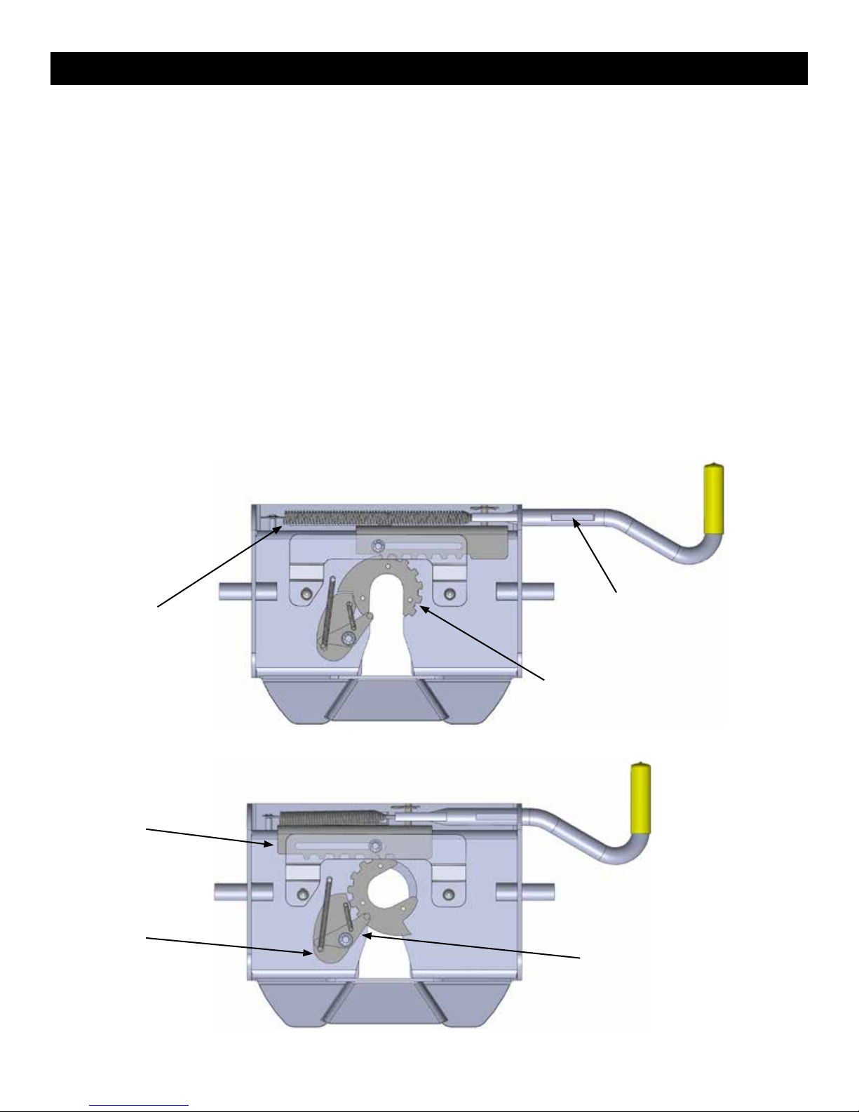
HOW DOES THE SUPERGLIDE WORK?
The SuperGlide is an automatically sliding Fifth wheel hitch based on a mechanical, cam action. Other sliding hitches
on the market today require you to get in and out of the vehicle multiple times before and after a turn, throwing levers to
allow it to move back and forth. The cam action of the SuperGlide hitch is truly automatic. When installed in your short
bed truck and used in conjunction with our Capture Plate, the SuperGlide “glides” along the Way Tubes with ease, making
turns automatically, without you having to ever get out of your vehicle. Here’s how it works:
Equipping your trailer’s king pin box with one of our
Capture Plates (required for the hitch to function properly
and sold separately), restricts the king pin on your trailer
from turning in the Fifth wheel plate on the SuperGlide
(#3601 pictured with a #3317 Capture Plate). Once the truck
begins to make a turn, the “captured” Fifth wheel plate
forces the large roller of the turntable cam arm assembly
to rotate and roll along the path of the cam slot to
begin the turn. This action pulls the plate and turntable
assembly, with trailer in tow, away from the cab of your
truck. The more you turn, the more it moves back.
wedge
It is important to note that the width of the trailer and
the location of the king pin in relation to the “nose”, or
Universal
Capture Plate
leading edge of the trailer, is critical in determining if
your truck and trailer are compatible to be used with a
SuperGlide. Short bed trucks have only so much room
from cab-to-axle; if your king pin is located too far under the nose of the trailer, the cam action of the SuperGlide may not
move the trailer back fast enough to allow the necessary clearance.
Another important point in the use and maintenance of your SuperGlide is the need to lubricate the moving parts.
SuperGlide hitches manufactured after November 2009 are equipped with Plastic Wear Plates and require a light oil
application to enhance the movement of the Turntable Cam Arm Assembly on the Way Tubes.
The #2700, #2900 and #2300 SuperGlides are equipped with Plastic Wear Plates on the Turntable/Cam Arm Assembly
to eliminate the need for constant lubrication between the metals of the Turntable and the Way Tubes. It is important
to protect the Plastic Wear Plates from possible
damage by keeping the Way Tubes free from rust
and corrosion by applying a coating of light oil on the
Tubes and the Turntable Shaft.
h wheel plate
way tubes
BEFORE OPERATING YOUR SUPERGLIDE
HITCH, YOU MUST READ THE “LUBRICATION”
SECTION. IF YOU HAVE ANY QUESTIONS
REGARDING LUBRICATION OR HOW THE
SUPERGLIDE FUNCTIONS, PLEASE CONTACT
OUR CUSTOMER SERVICE DEPARTMENT
AT (800) 443-2307 BEFORE USING YOUR
SUPERGLIDE.
Page 2
CUTAWAY VIEW (#2700 shown above)
roller
cam arm
turntable

CAUTION
• The width of the trailer and the location of the king pin in relation to
the “nose” (Dimension A), or leading edge of the trailer, is critical in
determining if your truck and trailer are compatible to be used with
a SuperGlide. If your king pin is located too far under the nose of
the trailer, the cam action of the SuperGlide may not move the trailer
back fast enough to allow the necessary clearance. Call PullRite
Customer Service at (800) 443-2307 with trailer width, make and year
of truck, and the distance of the king pin from the leading edge of the
trailer (Dimension A).
• Using a trailer that has a long rear slope to the king pin box hangar,
“B”, may cause damage to the king pin box or the inside edge of the
truck bed. Dimension “B” must be less than one half the width of the
inside top edges of the bed during turns for proper clearance.
• The SuperGlide hitch is equipped with a side-to-side pivot feature.
There should be a minimum of 6” between the truck bed rails
and the under side of the trailer for side tilt clearance. It is the
customers responsibility to adjust the trailer king pin box for the
appropriate amount of clearance depending on the terrain being
traveled (example: some State Parks are sloped and unpaved;
some driveways are steeply angled). If after-market bed covers are added, care must be taken to allow for additional
clearance.
A
B
• The SuperGlide hitch is designed to allow you to make a 90 degree turn. Please use extreme caution when turning
this far. In addition to putting stress on the wheels and axles of your trailer, if you make a turn greater than 90 degrees
the trailer will contact your truck and you WILL damage various parts of the hitch which will NOT be covered under the
Manufacturers Warranty.
• Position your brake-away cable so the slack in the cable will not be allowed to catch on the hitch during turns or lodge
in the cam mechanism. Failure to modify the length may cause the cable to catch on protruding parts of the hitch
which could activate the trailer brake, causing damage to the truck, trailer or hitch. Resulting damages will not be
covered by warranty.
• Position or coil any slack in your 7-way electrical cable out of the way of your moving hitch. It is preferred that the
plug and cabling remain isolated rearward of the hitch (nearest the tailgate) to prevent damage. Make slow test turns
while observing the 7-way cable until you are satised that it will not become caught in the hitch mechanism.
• FOREIGN DEBRIS: Anything carried in the bed of your truck during towing will need to be well secured. Remove
any foreign debris that might move around in the bed and contact the hitch. This will help to ensure that nothing
will get caught in or jam the movement of the cam which can cause damage to the hitch.
TESTING CLEARANCE
When you are assured your trailer is safely hooked up, pull forward and slowly start to turn. Make sure that someone is
outside watching the distance between the cab and the trailer. The distance between the cab and trailer should be greater
than two inches at all points of the turn. Specically watch the distance when the corner of the trailer is closest to the cab
and also when nearing a 90 degree turn. The minimum two inches of clearance is needed for normal driving conditions.
The practice of testing clearance will let you know how much clearance you actually have should you encounter adverse
road conditions.
Example: It is possible for the trailer to hit the cab when turning through a dip where the corner of the trailer
is closest to the cab or when nearing a 90 degree turn.
Page 3

BASE RAIL FOOT ASSEMBLY
The Industry Standard SuperGlides are equipped with base feet that must be attached to the base rails by the installer
prior to mounting the adjustable base unit.
There are two groups of holes on each side of the base assembly that will allow you to move the Base Rail Foot
Assemblies fore-to-aft, locating the trailer’s king pin over the axle.
It is the responsibility of the installer and SuperGlide owner to position the base so
the trailer does not come in contact with the cab during a turn.
Make certain that you have a minimum of two or more inches of clearance between the truck cab and trailer as they pass
each other. A reasonable range of vertical movement will insure that when the truck and trailer are passing through areas
of rough terrain and signicant dips in the road, there is room for the trailer to “ex” without contacting the cab.
INSTALLING THE BASE RAIL FEET
1. Determine which hole setting on the base unit will position your king pin over the axle (see illustration below).
2. Secure the Base Rail Foot Assemblies, to the hole settings you have chosen on the base, with the ½” bolts, ½” at
washers and ½” nuts, loosely tighten.
3. Install the SuperGlide on the base rails already installed in the truck bed, making certain the feet are seated
completely in the base rail slot.
4. Secure the Base Rail Foot Assemblies with the Hitch Pins and #9 Pin Clips provided in the SuperGlide package.
cab to axle
measurement
Page 4

BASE RAIL FOOT ASSEMBLY
5. To minimize any forward and aft movement when towing, secure the feet as far apart, fore-to-aft, as the slot opening
on the base rail will allow. If you still experience movement, consider loosening the base rail fasteners and tapping the
base rails toward each other to achieve optimal positioning.
6. Torque the bolts to 75 ft. pounds.
7. An aftermarket, ½” Locking Hitch Pin, may be used in place of one or more of the standard Hitch Pin and Clips to
prevent theft.
hitch pin
BASE RAIL FOOT ASSEMBLIES — EXPLODED VIEW
#2911 base rail feet
22”
# 9 pin clip
Page 5

LUBRICATION
DO NOT OPERATE HITCH UNTIL YOU READ THIS SECTION!
The SuperGlide hitch was designed to allow the Turntable Cam Arm Assembly to “glide” along two metal tubes, called
the Way Tubes. Since it’s release in 1998, we have made several advancements in the design, strength, and durability
of these components. November 2009 brings a new innovation from PullRite Towing Systems with the use of plastics.
The Turntable Cam Arm Assembly is now equipped with Plastic Wear Plates. It is imperative that you read each of the
following sections so you can learn how to care for your hitch properly.
MAINTENANCE
Inspect all mounting bracket and hitch hardware, that it is securely fastened. The Fifth Wheel Plate should be removed
and inspected, checking all moving parts for wear—clean as directed above. Inspect all mounting bolts periodically for
tightness and general condition, and re-torque if necessary. 1/2’ bolts to 75 ft. lbs., and 5/8” bolts to 150 ft. lbs.
#2300 and #2700 models utilize a castle nut and pin in the roller assembly. To re-torque, tighten roller bolt to a minimum
of 125 ft. lbs., then tighten more until next nut slot aligns with the stud cotter pin hole. Install cotter pin and bend one leg
upward.
When storing the SuperGlide hitch, you should be sure that the Fifth Wheel Plate parts and Way Tubes are lubricated with
WD-40 to retard the formation of rust. Cover the entire assembly to prevent accumulation of dirt, grime, or rust.
HITCH LUBRICATION
Plastic Wear Plates
The Plastic Wear Plates of the SuperGlide’s Turntable Cam Arm Assembly were designed to glide along the surfaces
without the need for heavy lubrication. To protect against rust and to enhance the ease of turning on the Way Tubes,
a light oil (WD-40 or a 3-in-1 oil) should be applied to the Way Tubes’ top and inward facing sides and between the
front and rear openings in the Plastic Wear Plates positioned around the Turntable/Cam Arm Shaft.
A light lubricant that is applied more frequently (each day of use) is preferred over the use of heavier lubricants.
Since any applied lubricant is going to be “wiped” off by the sliding action of the hitch, a light lubricant applied more
frequently will perform better (reduce the friction between the plastic and steel surfaces), and will be less messy, as
well as attract less dust and dirt. Heavy grease will be “wiped” off just as fast as light lubricant pushing the heavy
grease to areas that will not benet the wear surfaces - only making it appear that the hitch is still well lubricated.
You will nd with use, that the Plastic Wear Plate will wear the shiny zinc coating off the Way Tubes in areas, creating
“bare” areas of the metal, as well as light scoring marks in areas of repeated use. This is normal, but will be protected
as you apply WD-40 to the Way Tubes with each day’s use.
If your hitch is unused for more than a day or it is in storage, rust can form quickly in these areas. If rust does form,
simply use steel wool or lightly sand those areas. Never let your tubes become pitted with rust, as it may cause the
plastic to tear or catch on rough areas. The Plastic Wear Plate has a long life expectancy, but depending on how
often, and what terrains you are traveling, the plastic will eventually, wear down with time. If the 1/4” plastic plate
wears down to 3/16”, it should be replaced.
WARNING: Do not use any lubrication other than a light oil on the Way Tubes of your SuperGlide hitch. Using other
lubricants, such as those with a silicone base, will create a residue and may hinder the functionality of
the Turntable Cam Arm Assembly. Buildup of old oil and dirt can also create a residue over time and
needs to be kept clean.
Page 6

LUBRICATION
DO NOT OPERATE HITCH UNTIL YOU READ THIS SECTION!
1. WAY TUBES: Cover the tops and inside face of each Way Tube
2. TURNTABLE SHAFT: Using a directional straw attached to the spray nozzle, direct oil between the openings in
the Plastic Wear Plates at both the front and rear
3. PIVOT BOLT AND ROCKER ARM: Inspect and lubricate the Pivot Bolt monthly with axle grease when heavily
used, or annually with light use.
To remove the pivot bolt for
lubrication:
rocker arm
pivot bolt
• Remove the Fifth Wheel
Plate {A} from the Rocker
Arm.
• Remove the Hex Nut {C3}
and Lock Washer {C4} from
the Rocker Arm Pivot Bolt
{C1}.
• Place downward force,
compressing the Rocker
Arm Spring, enabling the
Pivot Bolt to be removed.
• Lube the Pivot Bolt
generously with a quality
axle grease and reinstall.
Tighten the Pivot Bolt to
the point where there is
resistance when you move
the Rocker Arm side-to-side.
4. HITCH PINS: A light coating of lubricant on the hitch pin and clips will help you install and reinstall them easily.
Passenger side Way Tube removed for illustrative purposes
3
2
The plate and it’s moving parts should be lubricated with
a light lubricant such as WD-40 or 3-in-1 oil, before each
trip or as needed. Be sure the plate is free of dirt and old
oil buildup. Pull the Release Handle repeatedly so that the
lubricant will spread among the moving parts that may not
have otherwise been covered sufciently.
Be sure the trailer’s king pin is clean and free from rust. A
light coating of WD-40 or other similar lubricant should be
used on the king pin.
FIFTH WHEEL PLATE & KING PIN
1901 plate
Page 7
FIFTH WHEEL PLATE OPERATION
A better understanding of the plates locking and un-locking operation can be obtained by viewing the working parts from
the underside of the plate (#3601 plate pictured below). The Fifth Wheel Plate {A} can be removed and turned over to
view the workings of the mechanism. When operating the Fifth Wheel Plate manually, please be aware that the Lock
Jaw Assembly has more movement capability when there is not a king pin present to center the assembly. Refer to the
illustrations below for part identication.
1. To open the locking mechanism, lift and pull the Release Handle out until the Lock Catch engages the Lock Jaw
Assembly (see illustrations on the opposite page).
2. As the trailer king pin moves into the plate, it will contact the Lock Lever, forcing the Lock Catch to disengage the Lock
Jaw Assembly, allowing the Lock Bar Spring to close the Lock Jaw Assembly behind the King Pin. The King Pin must
be fully engaged in the plate slot or the Lock Jaw Assembly will not seat properly, and the Handle Catch would not
then engage the inner side wall of the plate. To be certain that the Lock Jaw Assembly has closed fully, attempt to pull
the Release Handle without rst lifting it.
NOTE: Please note that when lifting the handle to clear the side wall of the plate with the handle catch, it will be
necessary to pull with some force to begin the Lock Jaw rotation. Merely lifting the Release Handle will
not cause the Handle to “pop” open and rotate the Lock Jaw to the open position.
3. To discourage theft or pranksters, place a padlock through the obround hole above the Release Handle (see
Illustration below; not available for #2900 and #2300 SuperGlide).
Lock Bar Spring
Lock Bar
Lock Catch
Handle Catch
Lock Jaw Assembly
OPEN -- UNLOCKED POSITION
Lock Lever
CLOSED -- LOCKED POSITION
Page 8

FIFTH WHEEL PLATE OPERATION
CAUTION: DO NOT ATTEMPT TO TRIP THE LOCK MECHANISM WITH YOUR HAND. USE A PROBE DEVICE
TO SIMULATE THE KING PIN ACTION
CLOSED
LIFT UPWARD
AND PULL
OUT WITH
FORCE UNTIL
LOCK CATCH
ENGAGES
OPEN
(feature available only on #2700 SuperGlide)
Page 9

HITCHING
WARNING: Never perform any of the following actions while any part of a person is between the vehicle and trailer.
1. Align your truck with the center of the trailer. The truck should be close to parallel to the centerline of the trailer.
Hitching can only be accomplished when the tow vehicle and the trailer are aligned within 10° of each other (see
below).
2. Block the trailer wheels so the trailer will not roll back.
3. Lower your tailgate and back up until there is about 6” of clearance between the SuperGlide hitch and the end of the
Capture Plate (sold separately and installed on your trailer’s king pin plate). Raise or lower the front of the trailer so
the bottom of the Capture Plate is aligned slightly above the beginning of the ramp area of the Fifth Wheel Plate. This
procedure will cause the front edge of the Capture Plate to “ride up” the ramp and atten or tilt the hitch plate into a
parallel position.
10
10
•
•
CAUTION: If this procedure is not followed, the king pin may bind in
the plate mechanism and not lock-in properly. Following the
procedure as outlined in Step 3 will ensure that you will not “high
hook” the king pin in the plate. “High hooking” occurs when
backing your hitch into a trailer that is set too high, resulting in
Ramp
the lower ange of the king pin to wedge itself against the metal
edge of the lower horseshoe piece or against the Lock Jaw
Assembly. Damage to the Lock Jaw Assembly may result and
not allow smooth operation of the closing mechanism.
SuperGlide
4. The Fifth Wheel Latch must be in the open position (see illustration on
Trailer Plate
pg. 10). Lift and pull out on the Release Handle to open the Lock Jaw
Assembly.
CAUTION: Damage will result should you attempt to hook up with the Lock
Jaw Assembly in the closed position.
5. Back up the truck in one uid motion, so the king pin enters the center of the Fifth Wheel Plate {A} opening.
6. Make sure the Lock Jaw Assembly is completely seated around the king pin.
7. Be sure that the Release Handle has fully returned to the closed position and proceed to “Safety Checks” on pg. 13.
Page 10

SAFETY CHECKS
1. Shine a light on the Fifth Wheel Plate Lock Jaw Assembly making sure it has closed around the king pin.
2. Pull the Release Handle towards you without lifting it up. If the Lock Jaw Assembly is completely closed the Handle
Catch will prevent you from being able to pull the Release Handle open.
3. Raise the trailer jack base plates just above the ground, lock your trailer brakes, then pull the tow vehicle slowly
forward putting a strain on the trailer.
4. When you are assured that the trailer is safely hooked up, raise your trailer jacks into their full retracted position.
FAILURE TO PERFORM THESE SAFETY CHECKS MAY RESULT IN DAMAGES TO TRUCK AND TRAILER.
UNHITCHING
WARNING: Never perform any of the following actions while any part of a person is between the vehicle and the trailer.
1. Once you have the trailer located and are ready to unhitch, (unhitching can only be accomplished when the truck and
trailer are aligned within 10 degrees of each other--see previous page), block the trailer wheels so it will not roll back
or forward. Back into the blocked trailer slightly and set the parking brake while you are still in gear. This action will
relieve pressure on the lock mechanism before attempting to release the latch mechanism.
2. Lower the trailer jacks to the point of just touching the ground but do not raise the trailer at this point.
3. Open the Lock Jaw Assembly by rst lifting, then pulling the Release Handle towards you (see pgs. 10 & 11).
4. Lower the trailer jacks until the bottom of the king pin box is almost free of the top of the Fifth Wheel Plate {A}. Make
certain that the bottom of the king pin is not so high that binding on the hitch Lock Catch would result.
5. After lowering the truck’s tail gate, disconnect the trailer electrical cord and break-away switch cable, then pull
forward.
6. As the king pin slides from the Fifth Wheel Plate, notice that the locking mechanism remains open once the king pin is
removed.
CAUTION: If it should be necessary to reposition your trailer, you must follow the hitching procedures to ensure the
hitch is latched before moving the trailer.
CAUTION: You may wish to keep the plate closed until you are ready to re-hitch to avoid injury or accidents to
children or adults who attempt to operate the plate mechanism. DO NOT ATTEMPT TO TRIP THE LOCK
MECHANISM WITH YOUR HAND, USE A PROBE TO SIMULATE THE KING PIN.
Page 11
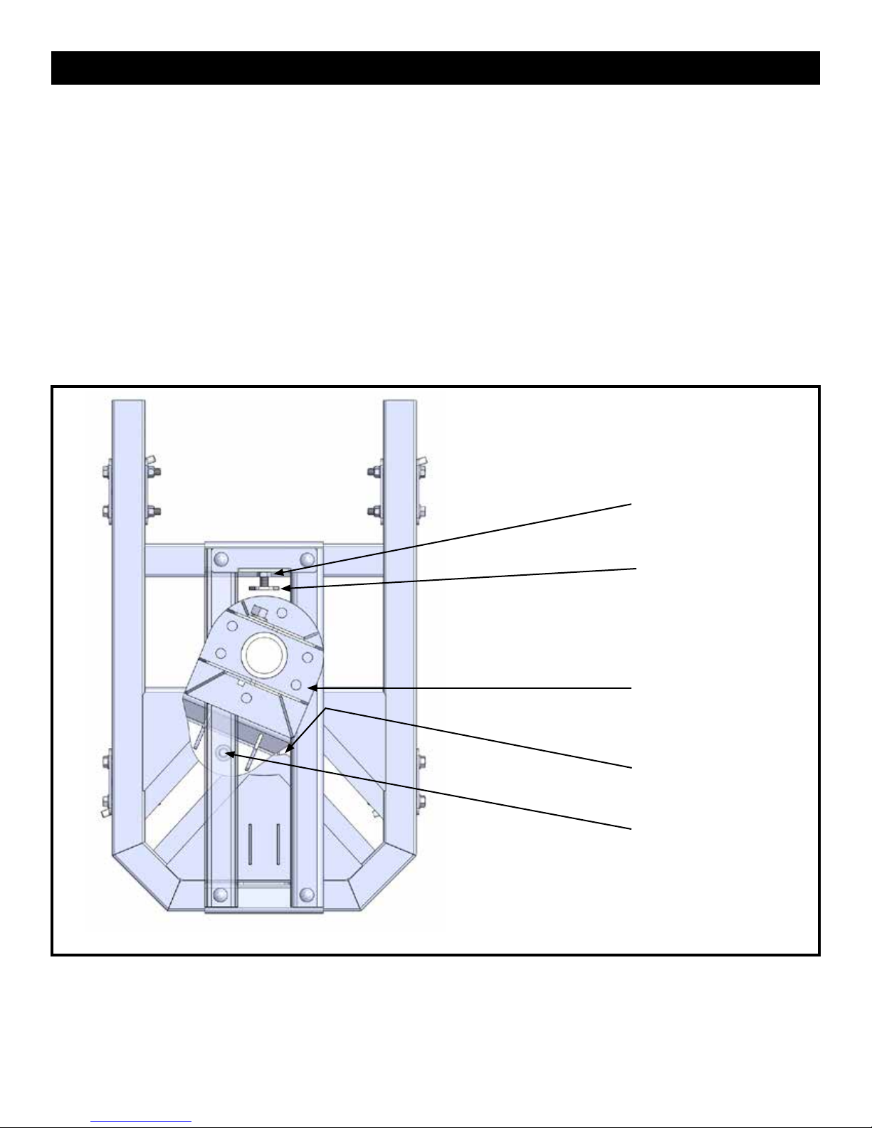
ADJUSTING THE TURNTABLE CAM ARM ASSEMBLY
This adjustment will need to be made periodically. If you are experiencing a bump or “clunk” when starting or stopping,
or if the hitch is sliding up and down the way tubes when you are not hooked up to the trailer you can perform this
adjustment to reduce the noise and keep the hitch in the forward towing position when not trailering.
1. The Turntable Cam Arm Roller {C2} needs to be kept snug against the rear edge of the of the Cam Slot (see below).
2. To adjust, loosen the Jam Nut located on the Threaded Stop Assembly {E1}, under the Fifth Wheel Plate {A} (on the
side facing the cab of your truck).
3. Adjusting the Threaded Stop Assembly’s hex-shaped plate, will remove excessive play from between the Cam Slot
and the Turntable Cam Arm Roller.
4. Turn the hex-shaped plate of the Threaded Stop Assembly by hand, adjusting incrementally, until it is difcult to pull
the Turntable/Cam Arm Assembly by hand, into the angled Cam Slot. While holding the hex-shaped plate in place,
tighten the Jam Nut with a wrench.
Threaded Stop
Assembly Jam Nut
Threaded
Stop Assembly {E1}
Turntable Cam Arm
Assembly {C}
Cam Slot (rearward)
Roller {C2}
Page 12
16K Base

CHALLENGE VS. SOLUTION
CHALLENGE SOLUTION
Cannot open the Release Handle. You may have too much rearward pressure against the lock
mechanism. Back your truck slightly to relieve pressure and
continue the unhitching procedures.
If you have positioned the trailer jacks too high, your king pin will
be pulled up against the bottom of the jaw, not allowing the jaw
to rotate open.
Plate seems dry – Can I use a Teon pad? No. The Trailer Plate does not allow for any extra space for a pad.
Since the turning action is no longer at the king pin, you will
have minimal friction. A light coating of WD-40 or a light oil is
sufcient.
Trailer overhang is hitting the truck bed rails when
the trailer and truck are at sharp angles.
The latch handle mechanism seems too stiff to
operate.
I have attempted to unhitch at an angle greater
than 10 degrees, truck to trailer, and the hitch
will not release the King Pin.
I need to have a professional evaluate my
SuperGlide.
Most trailer king pin boxes have height adjustment settings
available to achieve the necessary clearance between the
truck bed rails and the bottom of the trailer. Adjust accordingly.
Turn the plate upside-down and spray the locking mechanism with
WD-40. Work the handle until it slides freely. If the problem
persists, you may need to degrease and re-lube all working
parts.
Back into the King Pin, then using a probe, push the Lock Lever
forward until the Lock Catch allows the Lock Jaw Assembly
to rotate around the king pin. Retract the trailer jacks and
remove the wheel chocks. Maneuver the truck until it is lined
up within the 10 degree limit (see pg. 12). Perform unhitching
steps 1-6 on page 13.
Refer to #7 on page 17 for emergency situations during hooking
and unhooking your trailer.
Contact PullRite’s Customer Service Dept. at (800) 443-2307.
Your needs will be assessed and resolved by PullRite, or you
will be directed to an authorized PullRite Service Center.
Page 13

FREQUENTLY ASKED QUESTIONS
1. Can I pull other Fifth wheel trailers with my SuperGlide hitch?
Your SuperGlide hitch can only pull trailers equipped with the SuperGlide Capture Plate. If you hook up
to a trailer that does not have a Capture Plate installed, there is no control to keep the hitch in the forward
towing position and the weight of the trailer will cause the head to turn and slam or “free fall” to the rear
of the hitch’s angled cam slot, which may cause damage to the hitch, truck, and the king pin. We do not
recommend locking the hitch in any way to keep it in the forward position.
2. Will a standard hitch be able to tow my trailer with the Capture Plate installed?
The Capture Plate will need to be removed from the pin box before a standard fth wheel hitch can tow
your trailer. If the plate is not removed, the king pin will not rotate in the hitch and damage will result to
the Capture Plate and conventional hitch. Part # 3336 is a conversion adapter (see pg. i) that will allow
a standard fth wheel hitch to tow your trailer with the Capture Plate installed. The adapter is used in
conjunction with your Fifth Wheel Plate, or “head” of the SuperGlide {A}.
3. Is there a cover available for my SuperGlide hitch?
Yes. It is part #2912 and is available from your RV Dealer or by calling Customer Service (not available for
#2300 SuperGlide at this time).
4. Can I put a bed liner in my truck after the hitch is installed?
The industry standard base rails can be installed over a spray-in bed liner. All other liners will require an
opening to be cut through the liner, to allow the base rails to install against the metal of the bed.
5. How much does my SuperGlide weigh?
#2700 -- 194 lbs.
#2900 -- 224 lbs.
#2300 -- 270 lbs.
6. Can I leave the hitch attached to my trailer and use the trailer jacks to lift the hitch out of the truck?
Yes, you can use the trailer jacks to lift the hitch out of the truck. The hitch should not however be left
hanging from the king pin. Once you have the hitch lifted out of the truck you should have a stand available
to lower the hitch onto for storage.
Page 14

FREQUENTLY ASKED QUESTIONS
7. Can I hook up or unhook at a 90 degree angle?
Hooking up can only be accomplished when the truck and trailer are aligned within 10 degrees of each
other. See “Hitching” on page 16 for more information on hooking up. Unhooking by pulling the release
handle can only be accomplished when the truck and trailer are aligned within 10 degrees of each other.
In emergency situations you can pull the clevis pins and clips that attach the Fifth Wheel Plate or “head”
assembly to the Rocker Arm, lower your landing gear and raise the trailer up until the Fifth Wheel Plate is
free from the Rocker Arm. Pull forward from under the parked trailer. At that point you can pull the Release
Handle, remove the head from the king pin and reattach it to your hitch with the clevis pins and clips.
8. Can I use a Teon disc or lube plate on the king pin plate?
The king pin box and SuperGlide plate or “head” move together and since there is no friction, there is no
need for any grease or a lube plate. Use of a Teon disc or lube plate would cause the king pin to be too
short and problems hooking up will occur.
Page 15

A
ILLUSTRATION — #2300 EXPLODED VIEW
B1
B2
B3
B4
B5
B6
C1
D2
D1
D
B
C2
C3
C4
C
E1
E
G
H
G2
G3
F1
F2
F
G4
F3
G6
G9
G4
G5
G6 G7
Page 16
G8

#2300 PARTS LIST
ITEM DESCRIPTION PART NO. QTY. MATERIAL
A FIFTH WHEEL PLATE ASSEMBLY 2901 1
B ROCKER ARM 2302 1 (See assembly components below in hardware kit)
C TURNTABLE CAM ARM 2303 1
C4 CAM ARM SHAFT WEAR PLATES 44120003 2
D ROLLER ASSEMBLY 2304 1
D1 ROLLER SLOTTED NUT 98150121 1 1”-14 SLOTTED NUT,
D2 ROLLER COTTER PIN 98410567 1 1/4” X 2” COTTER PIN
E TURNTABLE WAY TUBES 23060001 2
F
F1 THREADED STOP ASSEMBLY 440501 1
F2 THREADED STOP HEX JAM NUT 98150141 1 5/8”-11 HEX JAM NUT
F3 THREADED STOP BOLT 98010232 1 5/8”-11 X 3.5” HHCS GRD 5
G HITCH BASE 2307 1
H WAY TUBE BRACKET ASSEMBLY 2305 1
B1 ROCKER ARM CLEVIS PIN 98410111 2 #3 COTTER PIN
B2 #3 PIN CLIP 98410127 2 1-2” X 2” CLEVIS PIN
B3 ROCKER ARM SPRING 35100001 1 16 GA SPRING STEEL
B4 ROCKER ARM SPRING FLAT WASHER 98250160 1 5/16” ZINC FLAT WASHER
B5 ROCKER ARM SPRING LOCK WASHER 98200159 1 5/16” ZINC SPLIT LOCK WASHER
B6 ROCKER ARM SPRING BOLT 98010242 1 5/16”-18 X 3/4” HHCS GRD 5
C1 ROCKER ARM PIVOT BOLT 98010147 1 3/4” -10 X 7” GRD 5
C2 PIVOT BOLT HEX NUT 98150131 1 3/4” - 10 ZINC HEX NUT
C3 PIVOT BOLT LOCK WASHER 98200124 1 3/4” ZINC PLATED SPLIT LOCK WASHER
E1
G2 WAY TUBE HOLDER BOLT 98010177 2 1/2”-13 X 1-1/4” HHCS GRD 5
G3 1/2” FLAT WASHER 98250145 10 1/2” FLAT WASHER
G4 5/8” FLANGE NUT 98150200 5 5/8”-11 SERRATED FLANGE NUT
G5 BASE RAIL FOOT BOLT 98010191 8 1/2”-13 X 4” HHCS GRD 5
G6 1/2” FLANGE NUT 98150201 10 1/2”-13 ZINC SERRATED FLANGE NUT
G7 HITCH PIN 27090001 4 1/2” ROUND
G8 #9 PIN CLIP 98410143 4 #9 COTTER PIN
G9
CAM ARM STOP ASSEMBLY
WAY TUBE BOLT
BASE FOOT ASSEMBLY 291101 4
2308 1
HARDWARE KIT
98050130 4 5/8”-11 X 8” CARRIAGE BOLT GRD 5
BASE RAILS ARE DIFFERENT FOR EACH APPLICATION AND ARE SOLD SEPARATELY. CALL (800) 443-2307 FOR MORE INFORMATION.
BASE RAIL KIT
Page 17

A
B1
B2
ILLUSTRATION — #2900 EXPLODED VIEW
B
B3
B4
B5
B6
C1
C2
D1
C
C3
C4
C5
E1
D2
D
F1
F2
G
E2
E3
E
F
F5
F3
F4
Page 18

#2900 PARTS LIST
ITEM DESCRIPTION PART NO. QTY. MATERIAL
A FIFTH WHEEL PLATE ASSEMBLY 2901 1
B ROCKER ARM 3302 1
C TURNTABLE CAM ARM 2903 1
C2 ROLLER 2904 1 ROLLER ASSEMBLY
C5 PLASTIC WEAR PLATE KIT 2910 1 MOLDED PLASTIC WEAR PLATES
D TURNTABLE WAY TUBES 2906 2
E CAM ARM STOP ASSEMBLY 2705 1
E1 STOP ASSEMBLY BOLT 98010219 1 5/8”-11 X 2-1/2” TAP BOLT GRD 5
E2 STOP ASSEMBLY JAM NUT 98150141 1 5/8”-11 HEX JAM NUT
E3 THREADED STOP ASSEMBLY 4405 1
F HITCH BASE 2907 1
HARDWARE KIT
B1 #3 PIN CLIP 98410127 2 #3 COTTER PIN
B2 ROCKER ARM CLEVIS PIN 98410111 2 1-2” X 2” CLEVIS PIN
B3 ROCKER ARM SPRING 35100001 1 16 GA SPRING STEEL
B4 ROCKER ARM SPRING FLAT WASHER 98250160 1 5/16” ZINC FLAT WASHER
B5 ROCKER ARM SPRING LOCK WASHER 98200159 1 5/16” ZINC SPLIT LOCK WASHER
B6 ROCKER ARM SPRING BOLT 98010244 1 5/16”-18 X 1” HHCS GRD 5
C1 ROCKER ARM PIVOT BOLT 98010147 1 3/4” -10 X 7” GRD 5
C3 PIVOT BOLT HEX NUT 98150131 1 3/4” - 10 ZINC HEX NUT
C4 PIVOT BOLT LOCK WASHER 98200124 1 3/4” ZINC PLATED SPLIT LOCK WASHER
D1 WAY TUBE BOLT 98050113 4 1/2”-13 X 3-1/2” HHCS GRD. 5 CARRIAGE BOLT
D2 STOP BRACKET BRACE 27050001 1
F1 BASE BOLT 98010191 8 1/2”-13 X 4” HHCS GRD 5
F2 BASE FLAT WASHER 98250145 8 1/2” ZINC FLAT WASHER
F3 HITCH PIN 27090001 4 1/2” ROUND
F4 #9 PIN CLIP 98410143 4 #9 COTTER PIN
F5 BASE FOOT ASSEMBLY 291101 4
G 1/2” FLANGE NUT 98150201 12 1/2”-13 ZINC SERRATED FLANGE NUT
BASE RAILS ARE DIFFERENT FOR EACH APPLICATION AND ARE SOLD SEPARATELY. CALL (800) 443-2307 FOR MORE INFORMATION.
BASE RAIL KIT
Page 19

A
B1
B2
ILLUSTRATION — #2700 EXPLODED VIEW
B
B3
B4
B5
B6
C7
C6
C1
C5
D1
C
C2
C3
C4
D2
D
F1
F2
G
Page 20
E1
E2
E3
E
F5
F3
F4

#2700 PARTS LIST
ITEM DESCRIPTION PART NO. QTY.
A FIFTH WHEEL PLATE ASSEMBLY 3601 1
B ROCKER ARM 3302 1
C TURNTABLE CAM ARM 2702 1
C4 PLASTIC WEAR PLATE KIT 2910 1 MOLDED PLASTIC WEAR PLATES
C5 ROLLER ASSEMBLY 2913 1
C6 ROLLER SLOTTED NUT 98150121 1 1” - 14 SLOTTED NUT
C7 ROLLER COTTER PIN 98410567 1 1/4” X 2” COTTER PIN ZINC PLATED
D TURNTABLE WAY TUBES 2706 2
E CAM ARM STOP ASSEMBLY 2705 1
E1 STOP ASSEMBLY BOLT 98010219 1 5/8”-11 X 2-1/2” TAP BOLT GRD 5
E2 STOP ASSEMBLY JAM NUT 98150141 1 5/8”-11 HEX JAM NUT
E3 THREADED STOP ASSEMBLY 4405 1
F HITCH BASE 2907 1
HARDWARE KIT
B1 #3 PIN CLIP 98410127 2 #3 COTTER PIN
B2 ROCKER ARM CLEVIS PIN 98410111 2 1-2” X 2” CLEVIS PIN
B3 ROCKER ARM SPRING 35100001 1 16 GA SPRING STEEL
B4 ROCKER ARM SPRING FLAT WASHER 98250160 1 5/16” ZINC FLAT WASHER
B5 ROCKER ARM SPRING LOCK WASHER 98200159 1 5/16” ZINC SPLIT LOCK WASHER
B6 ROCKER ARM SPRING BOLT 98010244 1 5/16”-18 X 1” HHCS GRD 5
C1 ROCKER ARM PIVOT BOLT 98010147 1 3/4” -10 X 7” GRD 5
C2 PIVOT BOLT HEX NUT 98150131 1 3/4” - 10 ZINC HEX NUT
C3 PIVOT BOLT LOCK WASHER 98200124 1 3/4” ZINC PLATED SPLIT LOCK WASHER
D1 FRONT WAY TUBE BOLT 98050114 2 1/2”-13 X 3-1/4” HHCS GRD. 5 CARRIAGE BOLT
D2 REAR WAY TUBE BOLT 98050113 2 1/2”-13 X 3-1/2” HHCS GRD. 5 CARRIAGE BOLT
F1 BASE BOLT 98010191 8 1/2”-13 X 4” HHCS GRD 5
F2 BASE FLAT WASHER 98250145 8 1/2” ZINC FLAT WASHER
F3 HITCH PIN 27090001 4 1/2” ROUND
F4 #9 PIN CLIP 98410143 4 #9 COTTER PIN
F5 BASE FOOT ASSEMBLY 291101 4
G 1/2” FLANGE NUT 98150201 12 1/2”-13 ZINC SERRATED FLANGE NUT
BASE RAILS ARE DIFFERENT FOR EACH APPLICATION AND ARE SOLD SEPARATELY. CALL (800) 443-2307 FOR MORE INFORMATION.
BASE RAIL KIT
Page 21

#3336 Conversion Adapter
When your trailer’s king pin box has been equipped with any welded Capture Plate or bolted-on Universal Capture Plate, this adapter will allow
your trailer to be pulled by a non-SuperGlide hitch when used in conjunction with the head of your SuperGlide (sold separately #3336).
NOTE: Most SuperGlide customers elect to use a custom, removable capture plate, rendering this adapter unnecessary.
1. Remove the SuperGlide Fifth Wheel
plate (part# 3601) from the SuperGlide
hitch by removing both 1/2” x 2” clevis
pins (part #98410111) and pin clips
(part #98410127).
2. Slide the SuperGlide Conversion Adapter
onto the 5th wheel plate of the “brand X”
hitch as seen in Step 1, making certain the
Conversion Adapter is securely locked into
place.
3. Insert the SuperGlide Fifth Wheel Plate (your
SuperGlide hitch head) into the Conversion
Adapter “cradles,” and secure with the
1/2” x 2” clevis pins and clips.
4. The Conversion Adapter allows the king pin
to turn in the conventional style hitch when
hooked up to the trailer equipped with a
SuperGlide Capture Plate.
3601 SuperGlide
Fi h wheel plate
pin clip
Conversion Adapter
Step 1
clevis pin
NOTE: Hook-up must be performed in a
straight line.
MANUFACTURED BY:
PULLIAM ENTERPRISES, INC.
13790 East Jefferson Blvd.
Mishawaka, IN 46545
(574) 259-1520 • (800) 443-2307
info@pullrite.com • www.pullrite.com
i
Step 2
SuperGlide
Trailer Plate
Step 3
#3336 SG Conversion Adapter Instructions (rev. 10.1.14)

5 YEAR LIMITED WARRANTY
PULLIAM ENTERPRISES, INC. hereinafter referred to as “PULLIAM”, warrants to the rst retail owner only, this PullRite towing system
to be free from defects in materials and workmanship for a period of ve (5) years or 31,068 miles (50,000 km) after the installation
on purchaser’s vehicle, whichever occurs rst.
To validate this warranty, the rst retail owner must mail the provided warranty card to PULLIAM, or register online at www.
pullrite.com, within ten (10) days after installation of said towing system on his vehicle.
The owner is responsible for all normal and preventative maintenance described in the Owner’s Manual.
If any defect occurs which the owner believes is covered by this warranty within said ve (5) year period, the owner shall contact
PULLIAM immediately, either in writing or by telephone call, Attention Customer Service Department. The owner will be
instructed to return the hitch at his expense either to an authorized PullRite dealer or to PULLIAM to repair or replace any parts
necessary to correct defects in material or workmanship.
Repair or replacement shall be at the sole option of PULLIAM and shall be completed by or on behalf of PULLIAM free of charge
for materials and labor.
This warranty gives you speci c legal rights, and you may also have other right’s which vary from state to state.
THIS WARRANTY SPECIFICALLY EXCLUDES EACH OF THE FOLLOWING:
1. Defects in the product resulting from misuse, neglect, accident, loading beyond the vehicle’s
capacity, failure to comply with instructions contained in the Owner’s Manual or unauthorized
repairs, replacements, alterations or modi cations. “Unauthorized repair, replacements,
alterations” are those made without PULLIAM’S prior knowledge and consent.
2. Any incidental or consequential damage including, but not limited to, loss of use of the vehicle,
towing charges, vehicle rental, loss of time, inconvenience, travel, gasoline, lodging and telephone
expenses, loss of revenue and damages on account of personal injury and property damage.
(Some states do not allow the exclusion or limitation of incidental or consequential damages, so
these limitations may not apply to you).
3. Repairs or replacements of defects in any PullRite towing system, or part thereof, installed on any
vehicle which has been rented, leased or used for any commercial purpose.
4. Any representation, warranty of undertaking made by any dealer or third party beyond the scope
of the warranty herein expressed.
5. Any problem resulting in normal deterioration due to wear or exposure.
TO THE EXTENT PERMITTED BY LAW, IMPLIED WARRANTIES OF MERCHANTABILITY AND FITNESS FOR A PARTICULAR PURPOSE ARE
LIMITED IN DURATION TO FIVE YEARS FROM THE DATE OF INSTALLATION ON THE FIRST OWNER’S VEHICLE. (SOME STATES, HOWEVER,
DO NOT ALLOW LIMITATIONS AS TO DURATION OF IMPLIED WARRANTY, SO THOSE LIMITATIONS MAY NOT APPLY TO YOU)
ii

Product Warranty Registration
As an owner of a PullRite product, you must register your product to be considered for
warranty coverage. See Owners Manual for further details.
Please note, that you can also register online at www.pullrite.com/warranty.htm.
Name: ________________________________________________________________________________
Address: ________________________________________________________________________________
City: ____________________________ State: ______________ Zip: _________________
Email Address: ____________________________________________________________
Phone
(op onal): ____________________________
Purchase Price: ____________________________ Date of Purchase: __________________________________
Dealer’s Name: ____________________________________________
Dealer’s Address: ____________________________________________
Dealer’s City: ____________________________ Dealer’s State: ______________ Dealer’s Zip: _________________
Dealer’s Phone: ____________________________
Model Purchased: ____________________________________________
Vehicle Make: ____________________________ Vehicle Model: ______________ Vehicle Year: _________________
Vehicle Year: ____________________________ Vehicle Cab Style: ______________ Vehicle Bed Length: _________________
Did you receive an Owners Manual from the Dealer? Yes / No
What infl uenced you to buy your hitch? _____________________________________________________________________
Comments:
Page iii

MANUFACTURED BY:
PULLIAM ENTERPRISES, INC.
13790 East Jefferson Blvd.
Mishawaka, IN 46545
(574) 259-1520 • (800) 443-2307
info@pullrite.com • www.pullrite.com
U.S. Pat. No’s. 6,308,977 and 8,220,818
 Loading...