

Pullin Evolution Solar PES190, PES300D, PES210D, PES190I, PES210I Installation And Servicing Instructions
...
1
1
UNVENTED MAINS PRESSURE SOLAR WATER HEATERS
100 TO 300 LITRE CAPACITY
DIRECT AND INDIRECT MODELS
INSTALLATION AND SERVICING INSTRUCTIONS
PACK CONTENTS
Pullin Evolution unvented solar water heater incorporating immersion heater(s) and thermal controls
Factory fitted temperature/pressure relief valve l Cold water combination valve assembly l Expansion vessel
and mounting bracket l Tundish l Motorised valve (indirect models only) l Compression nuts and olives
Immersion heater spanner l Installation instructions
IMPORTANT: PLEASE READ ALL THESE INSTRUCTIONS BEFORE
COMMENCING INSTALLATION
PLEASE LEAVE THIS MANUAL WITH THE CUSTOMER FOR
FUTURE REFERENCE
NOTE: Prior to installation the unit should be stored in
an upright position in an area free from excessive damp
or humidity.
INTRODUCTION
The Pullin Evolution Solar is a purpose designed
unvented solar water heater. The unit has a stainless
steel inner vessel, which ensures an excellent
standard of corrosion resistance. The outer casing is
a combination of resilient thermoplastic mouldings
and corrosion proofed steel sheet. All products are
insulated with CFC/HCFC free polyurethane foam to
meet the latest European heat loss requirements
(see Table 4).
The unit is supplied complete with all the necessary
safety and control devices needed to allow connection to the cold water mains. All these components
are preset and not adjustable.
This appliance complies with the requirements of the
CE marking directive and is Kiwa approved to show
compliance with Building Regulations (Section G3).
The following instructions are offered as a guide to
installation which must be carried out by a competent plumbing and electrical installer in accordance
with Building Regulation G3, The Building Standards
(Scotland) Regulations 1990, or The Building Regulations (Northern Ireland).

2
Table 1: Unit weights
IMPORTANT NOTE:
THE PULLIN EVOLUTION SOLAR MUST BE INCORPORATED INTO A FULLY PUMPED SOLAR PRIMARY
CIRCUIT. CONTROL OF THE SOLAR PRIMARY IS
ACHIEVED BY THE USE OF EXTERNAL CONTROLS
NOT SUPPLIED WITH THE UNIT. CONTROL MUST BE
VIA A PURPOSE DESIGNED SOLAR HYDRAULIC
STATION AND SOLAR DIFFERENTIAL TEMPERATURE CONTROLLER.
GENERAL REQUIREMENTS
SITING THE UNIT
The Pullin Evolution Solar must be installed vertically.
Although location is not critical, the following points
should be considered:
• The Pullin Evolution Solar should be sited to
ensure minimum dead leg distances, particularly
to the point of most frequent use.
• Avoid siting where extreme cold temperatures
will be experienced. All exposed pipework should
be insulated.
• The discharge pipework from the safety valves
must have minimum fall of 1:200 from the unit
and terminate in a safe and visible position.
• Access to associated controls and immersion
heaters should be possible to allow for periodic
servicing and maintenance.
• Ensure that the base chosen for the Pullin Evolution Solar is level and capable of permanently
supporting the weight when full of water (see
Table 1).
The Pullin Evolution Solar has an operating pressure
of 3.5 bar that is controlled by the cold water combination valve assembly. The cold water combination
valve assembly can be connected to a maximum mains
pressure of 16 bar.
Wherever possible the mains supply pipe should be
22mm. We suggest the minimum supply requirements
should be 1.5 bar pressure and 20 litres per minute
flowrate. However, at these values outlet flow rates
may be poor if several outlets are used simultaneously.
The higher the available pressure and flow rate the
better the system performance.
OUTLET/TERMINAL FITTINGS (TAPS, ETC.)
The Pullin Evolution Solar can be used with most
types of terminal fittings. It is advantageous in many
mixer showers to have balanced hot and cold water
supplies. In these instances a balanced pressure
cold water connection should be placed between the
2 pieces of the cold water combination valve assembly (see Fig. 1). Outlets situated higher than the
Pullin Evolution Solar will give outlet pressures lower
than that at the heater, a 10m height difference will
result in a 1 bar pressure reduction at the outlet.
LIMITATIONS
The Pullin Evolution Solar should not be used in
association with any of the following:
• Solid fuel boilers or any other boiler in which
the energy input is not under effective thermostatic control unless additional and appropriate
safety measures are installed.
• Ascending spray type bidets or any other class
1 back syphonage risk requiring that a type A air
gap be employed.
• Steam heating plants unless additional and appropriate safety devices are installed.
• Situations where maintenance is likely to be neglected or safety devices tampered with.
• Water supplies that have either inadequate pressure or where the supply may be intermittent.
• Situations where it is not possible to safely pipe
away any discharge from the safety valves.
• In areas where the water consistently contains
a high proportion of solids, e.g. suspended matter
that could block the strainer, unless adequate filtration can be ensured.
OPERATIONAL SUMMARY
Maximum mains pressure 16 bar
Operating pressure 3.5 bar
Expansion vessel charge pressure 3.5 bar
Expansion relief valve setting 6 bar
T&P relief valve setting 90°C/10 bar
Maximum primary circuit pressure
(auxillary coil) (indirect only) 3 bar
Maximum primary circuit pressure
(solar coil) 6 bar
Storage capacity See Table 1
Weight when full See Table 1
WATER SUPPLY
Bear in mind that the mains water supply to the property will be supplying both the hot and cold water requirements simultaneously. It is recommended that the
maximum water demand is assessed and the water
supply checked to ensure this demand can be satisfactorily met.
Note: A high mains water pressure will not always
guarantee high flow rates.
Type
Model
reference
Nominal
capacity
(litres)
Weight of
unit full
(kg)
DIRECT PES190D 190 235
PES210D 210 259
PES250D 250 302
PES300D 300 362
INDIRECT PES190I 190 240
PES210I 210 264
PES250I 250 308
PES300I 300 367
3
3
INSTALLATION – GENERAL
(FIGS 3 & 5)
PIPE FITTINGS
All pipe fittings are made via 22mm compression
fittings directly to the unit. The fittings are threaded
3/4”BSP male parallel should threaded pipe connections be required.
COLD FEED
A 22mm cold water supply is recommended, however if a 15mm (1/2”) supply exists which provides
sufficient flow this may be used (although more flow
noise may be experienced).
A stopcock or servicing valve should be incorporated
into the cold water supply to enable the Pullin
Evolution Solar and its associated controls to be
isolated and serviced.
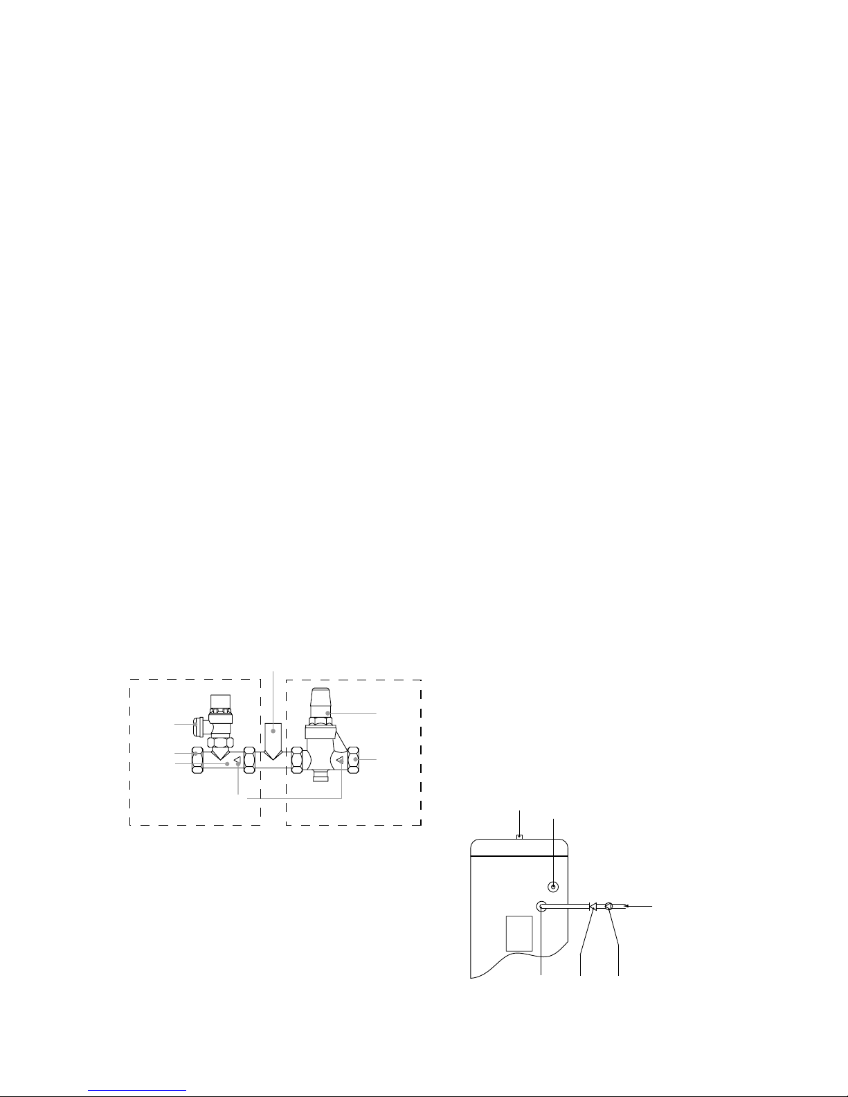
COLD WATER COMBINATION VALVE ASSEMBLY
(FIG 1)
The 2-piece cold water combination valve assembly
can be located anywhere on the cold water mains
supply prior to the expansion vessel (see Fig. 5) but
the two pieces do not have to be installed together.
The pressure reducing valve incorporates the
pressure reducer & strainer and the expansion valve
incorporates the expansion & check valves. Ensure
that the valves are installed in the correct order and
orientation. No other valves should be placed
between the expansion valve and the Pullin Evolution
Solar unit. A connection can be made between the
expansion and pressure reducing valves to provide a
balanced cold water connection. The expansion
valve connection must not be used for any other
purpose.
EXPANSION VESSEL
The expansion vessel accommodates expansion that
results from heating the water inside the unit. The
unit is pre-charged at 3.5 bar. The expansion vessel
must be connected between the expansion valve
(see Fig. 1) and the Pullin Evolution Solar (see Fig.
5). The location of the expansion vessel should allow
access to recharge the pressure as and when
necessary, this can be done using a normal car foot
pump. It is recommended that the expansion vessel
is adequately supported. An expansion vessel wall
mounting bracket is supplied for this purpose.
NOTE: DO NOT USE THE POTABLE WATER EXPANSION VESSEL SUPPLIED WITH THE PULLIN
EVOLUTION SOLAR FOR ANY OTHER PURPOSE. IT
IS NOT SUITABLE FOR USE ON A SOLAR
PRIMARY CIRCUIT.
SECONDARY CIRCULATION
If secondary circulation is required it is recommended
that it be connected to the Pullin Evolution Solar as
shown in Fig. 2. The secondary return pipe should be
in 15mm pipe and incorporate a check valve to prevent backflow. A suitable WRAS approved bronze circulation pump will be required. On large systems, due
to the increase in system water content, it may be
necessary to fit an additional expansion vessel to the
secondary circuit. This should be done if the capacity
of the secondary circuit exceeds 10 litres.
Pipe capacity (copper)
15mm o/d = 0.13 l/m (10 litres = 77m)
22mm o/d = 0.38 l/m (10 litres = 26m)
28mm o/d = 0.55 l/m (10 litres = 18m)
Secondary circulation is NOT recommended for direct
electric units being used on Off Peak electricity tariffs.
OUTLET
The hot water outlet is a 22mm compression fitting
located at the top of the cylinder. Hot water distribution pipework should be 22mm pipe with short runs
of 15mm pipe to terminal fittings such as sinks and
basins. Pipe sizes may vary due to system design.
DRAIN TAP
A suitable draining tap should be installed in the cold
water supply to the Pullin Evolution Solar unit
between the expansion valve (see Fig. 1) and the
heater at as low a level as possible. It is recommended that the outlet point of the drain pipework
be at least 1 metre below the level of the heater
(this can be achieved by attaching a hose to the
drain tap outlet spigot).
Fig. 1: Cold water combination valve assembly
Fig. 2: Secondary circulation connection
SECONDARY
CIRCULATION
PUMP
SECONDARY
RETURN
CHECK
VALV E
OUTLET
T&P RELIEF
VALV E
SECONDARY
RETURN
CONNECTION
INLET
OUTLET
EXPANSION
VALV E
OUTLET
PRESSURE
REDUCING
VALV E
CARTRIDGE
& STRAINER
DIRECTION OF FLOW
BALANCED COLD
WATER CONNECTION
(NOT SUPPLIED)
EXPANSION VALVE
PRESSURE REDUCING VALVE
CHECK
VALV E
4
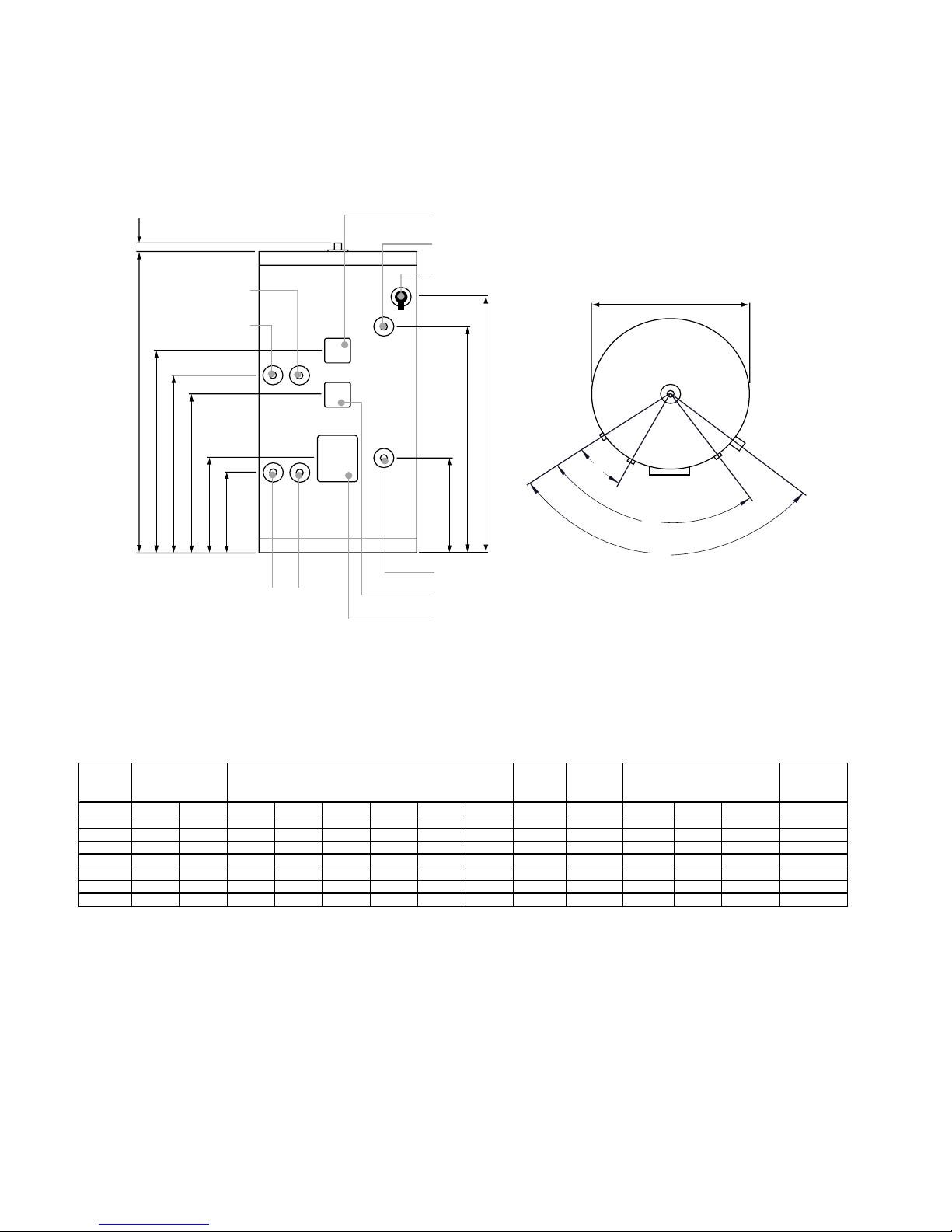
Fig. 3: General Dimensions and features
190
9
1372 950 740 1019 1.1 110 115
190
9
1372 732 803 923 1019 1.1 110 0.61 11.9 20
210
9
1473 1000 759 1184 1.1 130 136
210
9
1473 892 808 1095 1184 1.1 130 0.68 15.2 20
250
9
1731 1072 773 1391 1.1 163 171
250
9
1731 1160 883 1258 1391 1.1 163 0. 79 15.2 23
300
9
2038 1409 870 1715 1.1 198 208
300
9
2038 1438 1023 1573 1715 1.1 198 0. 79 17.4 25
NOTES:
SOLAR
SURFACE
AREA (m²)
FE
NOMINAL
CAPACITY
(lit res)
TYPE DIMENSIONS (mm)
ABCD
2. Direct heating t imes as sume us e of lower element only and auxillary cy linder volume being heated
SURFACE
AREA (m²)
RATING
(kW )
RECOVERY
(mins )
1. Recovery time based on heating 70% of auxillary volume through 45°C
AUXILLARY
VOLUME
(lit res)
AUXILLARY COIL HEATING
TIME DIRE CT
(mins )DIRECT INDIRE CT
370
433
D
C
B
A
29
412
E
F
SOLAR
PRIMARY
RETURN
SOLAR
PRIMARY
FLOW
AUX. BOILER RETURN
(INDIRECT ONLY)
AUX. BOILER RETURN
(INDIRECT ONLY)
AUX. BOILER FLOW
(INDIRECT ONLY)
T&P VALVE
SECONDARY
RETURN
BOOST IMM. HTR.
(DIRECT ONLY)
INLET
AUX. CONTROL
HOUSING
SOLAR CONTROL
HOUSING
Ø550
20°
75°
90°

5
5
Worked example of discharge pipe sizing
The example below is for a G1/2 temperature relief
valve with a discharge pipe (D2) having 4 No. elbows
and length of 7m from the tundish to the point of
discharge.
From Table 4:
Maximum resistance allowed for a straight length of
22mm copper discharge pipe (D2) from a G1/2
temperature relief valve is 9.0m.
DISCHARGE PIPEWORK
It is a requirement of Building Regulation G3 that any
discharge from an unvented system is conveyed to
where it is visible, but will not cause danger to
persons in or about the building. The tundish and
discharge pipes should be fitted in accordance with
the requirements and guidance notes of Building
Regulation G3. The G3 Requirements and Guidance
section 3.9 are reproduced in the following sections.
Information Sheet No. 33 available from the British
Board of Agrément gives further advice on discharge
pipe installation. For discharge pipe arrangements
not covered by G3 Guidance or BBA Info Sheet No.33
advice should be sought from your local Building
Control Officer.
G3 REQUIREMENT
“...there shall be precautions...to ensure
that the hot water discharged from safety
devices is safely conveyed to where it is
visible but will not cause danger to
persons in or about the building.”
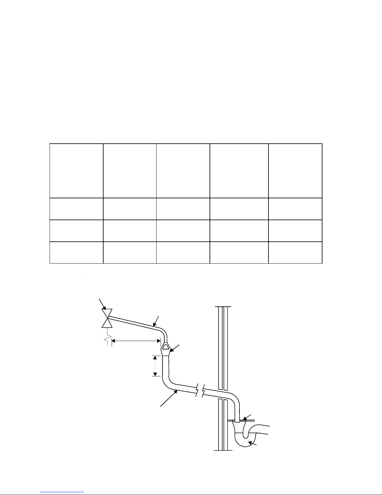
G3 GUIDANCE SECTION 3.9
The discharge pipe (D1) from the vessel up
to and including the tundish is generally
supplied by the manufacturer of the hot
water storage system. Where otherwise,
the installation should include the
discharge pipe(s) (D1) from the safety
device(s). In either case the tundish
should be vertical, located in the same
space as the unvented hot water storage
system and be fitted as close as possible
and within 500mm of the safety device e.g.
the temperature relief valve.
The discharge pipe (D2) from the tundish
should terminate in a safe place where
there is no risk to persons in the vicinity of
the discharge, preferably be of metal and:
a. be at least one pipe size larger than the
nominal outlet size of the safety device
unless its total equivalent hydraulic
resistance exceeds that of a straight pipe
9m long i.e. discharge pipes between 9m
and 18m equivalent resistance length
should be at least two sizes larger than
the nominal outlet size of the safety
device, between 18 and 27m at least 3
sizes larger , and so on. Bends must be
taken into account in calculating the flow
resistance. Refer to Diagram 1, Table 1 and
the worked example.
An alternative approach for sizing discharge pipes would be to follow BS
6700:1987 Specification for design installation, testing and maintenance of services supplying water for domestic use
within buildings and their curtilages,
Appendix E, section E2 and table 21.
b. have a vertical section of pipe at least
300mm long, below the tundish before
any elbows or bends in the pipework.
c. be installed with a continuous fall.
d. have discharges visible at both the
tundish and the final point of discharge
but where this is not possible or is practically difficult there should be clear
visibility at one or other of these locations.
Examples of acceptable discharge arrangements are:
i. ideally below a fixed grating and
above the water seal in a trapped gully.
ii. downward discharges at low level;
i.e. up to 100mm above external surfaces
such as car parks, hard standings,
grassed areas etc. are acceptable providing that where children may play or
otherwise come into contact with discharges a wire cage or similar guard is
positioned to prevent contact, whilst
maintaining visibility.
iii. discharges at high level; e.g. into a
metal hopper and metal down pipe with
the end of the discharge pipe clearly
visible (tundish visible or not) or onto a
roof capable of withstanding high temperature discharges of water and 3m
from any plastics guttering system that
would collect such discharges (tundish
visible).
iv. where a single pipe serves a number
of discharges, such as in blocks of flats,
the number served should be limited to
not more than 6 systems so that any
instalation discharging can be traced
reasonably easily. The single common
discharge pipe should be at least one
pipe size larger than the largest individual discharge pipe (D2) to be connected. If unvented hot water storage
systems are installed where discharges
from safety devices may not be apparent i.e. in dwellings occupied by blind,
infirm or disabled people, consideration
should be given to the installation of an
electronically operated device to warn
when discharge takes place.
Note: The discharge will consist of
scalding water and steam. Asphalt, roofing felt and non-metallic rainwater
goods may be damaged by such discharges.
6
Subtract the resistance for 4 No. 22mm elbows at
0.8m each = 3.2m
Therefore the permitted length equates to: 5.8m
5.8m is less than the actual length of 7m therefore
calculate the next largest size.
Maximum resistance allowed for a straight length of
28mm pipe (D2) from a G1/2 temperature relief
valves equates to 18m.
Subtract the resistance of 4 No. 28mm elbows at
1.0m each = 4.0m
Therefore the maximum permitted length equates
to: 14m
As the actual length is 7m, a 28mm (D2) copper pipe
will be satisfactory.
WARNINGS
• Under no circumstances should the factory fitted temperature/pressure relief valve be removed
other than by a competent person. To do so will
invalidate any guarantee or claim.
• The cold water combination valve assembly must
be fitted to the mains water supply to the Pullin
Evolution Solar unit.
• No control or safety valves should be tampered
with.
• The discharge pipe should not be blocked or
used for any other purpose.
• The tundish should not be located adjacent to
any electrical components.
Valve outlet size
Min imum size of
discharge pipe
D1
Min imum size o f
discharge pipe
D2 from tundish
Ma ximum
resistance
allowed, expressed
as a length of
straight pipe (i.e.
no elbows or
bends)
Resistance
created by each
elbow or bend
G1/2 15mm
22mm
28mm
35mm
up to 9m
up to 18m
up to 27m
0.8m
1.0m
1.4m
G3/4 22mm
28mm
35mm
42mm
up to 9m
up to 18m
up to 27m
1.0m
1.4m
1.7m
G1 28mm
35mm
42mm
54mm
up to 9m
up to 18m
up to 27m
1.4m
1.7m
2.3m
Table 2: Sizing of copper discharge pipe (D2) for common temperature relief valve outlet sizes
Fixed grating
Discharge below
fixed grating
(Building Regulation
G3 section 3.9d gives
alternative points
of discharge)
Trapped
gully
Discharge pipe (D2) from tundish,
with continuous fall. See Building
Regulation G3 section 3.9d i-iv,
Table 4 and worked example
300mm
minimum
500mm maximum
Metal discharge pipe (D1) from
Temperature relief valve to tundish
Tundish
Safety device
(e.g. Temperature
relief valve)
Fig.4: Typical discharge pipe arrangement (extract from Building Regulation G3 Guidance section)

7
7
Fig. 5: Typical installation - schematic
Fig.6 Electrical Connections (Schematic)
DIRECT MODELS
AUXILLARY HEATING CONTROL
EARTH
CONNECTION
THERMOSTAT
FUSED (13A) DOUBLE
POLE ISOLATING
SWITCH
1.5mm² 3-CORE
HOFR SHEATHED
CABLE
Note: On models fitted with two elements each element must
be wired individually in accordance with the diagram above
A
B
BLUE
BROWN
GREEN/
YELLOW
1
2
GREEN/
YELLOW
13 AMP MAINS
SUPPLY. 1.5mm
2
MIN. CABLE SIZE
TO INDIRECT SYSTEM
CONTROLS JUNCTION
BOX
GREEN/
YELLOW
BROWN
BLUE
3
DIRECT
THERMOSTAT
B
A
112
2
3
INDIRECT
THERMOSTAT
INDIRECT THERMAL
CUT-OUT
EXPANSION
VESSEL
COLD WATER
COMBINATION
VALVE
(2-PIECE)
T&P RELIEF
VALVE
TO HOT
OUTLETS
MAINS
WATER
SUPPLY
ISOLATING
VALVE (NOT
SUPPLIED)
TUNDISH
DISCHARGE
PIPE
DRAIN COCK
(NOT SUPPLIED)
SOLAR PRIMARY
RETURN
SOLAR PRIMARY
FLOW
SOLAR
CONTROLS
HOUSING
INLET
BOOST ELEMENT/
AUX. CONTROL
HOUSING
NOTE: AUXILLARY HEATING COIL FITTED ON 190 TO 300 INDIRECT MODELS ONLY
BALANCED
COLD WATER
CONNECTION
(IF REQUIRED)
AUX. PRIMARY
RETURN
AUX. PRIMARY
FLOW
SECONDARY RETURN TAPPING
(IF REQUIRED - INDIRECT ONLY)

8
INSTALLATION - DIRECT UNITS
PLUMBING CONNECTIONS
Direct units require the following pipework connections.
• Cold water supply to and from inlet controls.
• Outlet to hot water draw off points.
• Discharge pipework from valve outlets to tundish.
ELECTRICAL SUPPLY (FIG. 6)
Pullin Evolution Solar units are fitted with two 3kW
immersion heaters as standard. It is recommended
that these should be wired via a suitable controller
to BSEN 60730. The Pullin Evolution Solar MUST
be earthed.
All wiring to the unit must be installed in accordance
with the latest IEE Wiring Regulations and the circuit
must be protected by a suitable fuse and double pole
isolating switch with a contact separation of at least
3mm in both poles. The Live and Neutral connections
are made directly onto the combined thermostat and
thermal cut-out located under the terminal cover(s)
mounted on the front of the unit. The earth connec
tion should be made to the earth connection located
to the side of the immersion heater boss(es). The
supply cable must be routed through the cable gland
located on the unit casing beneath the terminal
housing.
DO NOT operate the immersion heaters until the
Pullin Evolution Solar has been filled with water.
INSTALLATION - SOLAR PRIMARY
CONNECTION TO SOLAR PRIMARY CIRCUIT
The lower (solar) coil of the Pullin Evolution Solar
must be connected to a fully pumped solar primary
circuit. The connections are suitable for 22mm
copper pipe direct to the compression fittings
provided. The connections are also threaded 3/4”
BSP male parallel should BSP be required.
The solar primary circuit should have its own
dedicated circulating pump and safety controls which
must be installed as per the manufacturers instructions.
CONTROL OF SOLAR PRIMARY CIRCUIT
Temperature control of the Pullin Evolution Solar
must be carried out using a suitable proprietory
Solar Controller/Programmer. The cylinder tempera
ture sensing probe (supplied with the solar control
ler) should be fully insterted into the pocket provided
on the Pullin Evolution Solar and its cable secured
using the cable clamps on the controls housing (see
Fig.7).
Connection to the solar controller should be in
accordance with manufacturer’s instructions. The
solar controller should be programmed to give a
cylinder temperature of approximately 60°C
(maximum 70°C).
SAFETY
DISCONNECT FROM THE MAINS SUPPLY BEFORE
REMOVING ANY COVERS. Never attempt to replace
the immersion heater(s) other than with the recommended Pullin immersion heater(s).
DO NOT BYPASS THE THERMAL CUT-OUT(S) IN
ANY CIRCUMSTANCES. Ensure the two male spade
terminations on the underside of the combined
thermostat and thermal cut-out are pushed firmly
onto the corresponding terminations on the element
plate assembly.
In case of difficulty contact service support; contact
details available at the back of this booklet.
Fig. 7: Solar Control Connections
The solar controller and solar primary circulation
pump must be wired via the over-temperature cut-
out mounted in the lower solar controls housing (see
Fig. 7). This will ensure that the heat input to the
solar coil is interrupted in the event of the cylinder
over-heating. There must also be suitable check
(non-return) valves installed in the solar primary
flow and return to prevent the possibility of any
thermo-syphoning if the solar circulation is stopped.
123
SOLAR DIFFERENTIAL
CONTROLLER
(NOT SUPPLIED)
SOLAR CYLINDER
CONTROLS HOUSING
CYLINDER
TEMPERATURE
CONTROL
PROBE
TERMINAL
BLOCK
OVER
TEMPERATURE
CUT OUT
L
N
CABLE
CLAMPS

9
9
INSTALLATION - AUXILLARY
HEATING COIL
PLUMBING CONNECTIONS
Indirect units require the following pipework
connections.
• Cold water supply to and from inlet controls.
• Outlet to hot water draw off points.
• Discharge pipework from valve outlets to tundish
• Connection to the auxillary primary circuit.
Primary connections are 22mm compression. However,
3/4”BSP parallel threaded fittings can be fitted to the
primary coil connections if required.
ELECTRICAL SUPPLY (FIG. 6)
All Indirect units are fitted with a 3kW immersion
heater and a combined thermostat and thermal cutout to control the primary heating source. The Pullin
Evolution Solar MUST be earthed.
All wiring to the unit must be installed in accordance
with the latest IEE Wiring Regulations and the supply
circuits must be protected by a suitable fuse and
double pole isolating switch with a contact separation of at least 3mm in both poles. Connection to the
immersion heater thermostat(s) are made in
accordance with the ‘INSTALLATION - DIRECT
UNITS’ section. All auxillary heating source (boiler)
connections are made to the terminal block located
under the terminal cover mounted on the side of the
unit. The supply cable(s) must be routed through the
cable grip(s) in the terminal housing.
DISCONNECT FROM MAINS SUPPLY BEFORE
REMOVING ANY COVERS. DO NOT BYPASS THE
THERMAL CUT-OUTS IN ANY CIRCUMSTANCES.
Ensure the thermostat and thermal cut-out sensing
bulbs are pushed fully into the pockets on the
element plate assembly.
BOILER SELECTION
The boiler should have a control thermostat and non
self-resetting thermal cut-out and be compatible
with unvented storage water heaters.
Where use of a boiler without a thermal cut-out is
unavoidable a “low head” open vented primary
circuit should be used. The feed and expansion
cistern head above the Pullin Evolution Solar should
not exceed 2.5m.
AUXILLARY PRIMARY CIRCUIT CONTROL
The 2-port motorised valve supplied with the Pullin
Evolution Solar indirect units MUST be fitted to the
primary auxillary circuit flow to the Pullin Evolution
Solar heat exchanger and wired in series with the
indirect thermostat and thermal cut-out fitted to the
unit.
Primary circulation to the Pullin Evolution Solar heat
exchangers must be pumped; gravity circulation
WILL NOT WORK.

10
Fig. 8: Schematic wiring diagram - Basic 2 x 2 port valve system
Fig.9: Schematic wiring diagram - 3 port mid position valve system. N.B. Must be used in conjunction with 2
port zone valve supplied
PROGRAMMER
BOILER
PUMP
ROOM STAT
ZONE VALVE (DHW)
(SUPPLIED)
ZONE VALVE (HTG)
CYLINDER
TERMINAL BLOCK
JUNCTION BOX
12345678910
12345678910
LNLN
G
Br Bl OGBrBlO
GY
1
32
L
N
2
3
HTG DHW
ON
ON
12 23 12
123
23
2
3
LN
(SUPPLY)
1
3
NOTES:
CONTROL TERMINAL NUMBERING MAY DIFFER FROM THOSE SHOWN.
REFER TO INSTRUCTIONS WITH CONTROLS SELECTED.
A DOUBLE POLE ISOLATING SWITCH MUST BE INSTALLED IN THE MAINS SUPPLY.
ALL EARTH CONNECTIONS MUST BE CONNECTED BACK TO THE MAINS EARTH SUPPLY.
CONTROL CIRCUIT FOR AUXILLARY HEATING BOILER ONLY.
SEPARATE CONTROLS WILL BE REQUIRED FOR THE SOLAR PRIMARY CIRCUIT.
PROGRAMMER
BOILER
PUMP
ROOM STAT
ZONE VALVE (DHW)
(SUPPLIED)
ZONE VALVE (HTG)
CYLINDER
TERMINAL BLOCK
JUNCTION BOX
12345678910
12345678910
LN
GBrBlOG
W
Bl O
GY
132
L
N
2
3
2
2
3 12
23
2
3
LN
(SUPPLY)
1
3
LN
HTG DHW
ON
ON
1 23
DHW
OFF
NOTES:
CONTROL TERMINAL NUMBERING MAY DIFFER FROM THOSE SHOWN.
REFER TO INSTRUCTIONS WITH CONTROLS SELECTED.
A DOUBLE POLE ISOLATING SWITCH MUST BE INSTALLED IN THE MAINS SUPPLY.
ALL EARTH CONNECTIONS MUST BE CONNECTED BACK TO THE MAINS EARTH SUPPLY.
CONTROL CIRCUIT FOR AUXILLARY HEATING BOILER ONLY.
SEPARATE CONTROLS WILL BE REQUIRED FOR THE SOLAR PRIMARY CIRCUIT.

11
11
COMMISSIONING
FILLING THE UNIT WITH WATER
• Check expansion vessel pre-charge pressure.
The vessel is supplied pre-charged to 3.5 bar to
match the control pressure of the pressure reducing valve. The pre-charge pressure is checked using a car tyre gauge by unscrewing the plastic cap
opposite the water connection.
• Check all connections for tightness including the
immersion heater(s). An immersion heater key
spanner is supplied for this purpose.
• Ensure the drain cock is CLOSED.
• Open a hot tap furthest from the Pullin Evolu-
tion Solar.
• Open the mains stop cock to fill the unit. When
water flows from the tap, allow to run for a few
minutes to thoroughly flush through any residue,
dirt or swarf, then close the tap.
• Open successive hot taps to purge the system
of air.
SYSTEM CHECKS
• Check all water connections for leaks and rec-
tify as necessary.
• Remove the pressure reducing valve headwork
to access the strainer mesh; clean and re-fit.
• Manually open, for a few seconds, each relief
valve in turn, checking that water is discharged
and runs freely through the tundish and out at the
discharge point.
• Ensure that the valve(s) reseat satisfactorily.
SOLAR PRIMARY CIRCUIT
Fill the solar primary circuit following the instructions
provided with the solar hydraulic controls. The
cylinder temperature control probe supplied with the
solar controller must be fully inserted into the pocket
in the lower controls housing and the cable securely
clamped. Heating by the solar primary circuit is
controlled by the solar controller; refer to the
manufacturer’s installation instructions for details of
how to set up and connect the solar primary circuit.
The solar controller should be programmed to give a
maximum storage temperature in the Pullin Evolution
Solar of 70oC; 60oC is recommended to minimise
scaling.
SECONDARY HEATING COIL
Fill the indirect secondary circuit following the boiler
manufacturer’s commissioning instructions. To
ensure the Pullin Evolution Solar auxillary heat
exchanger is filled, the 2 port motorised valve
(supplied) should be manually opened by moving the
lever on the motor housing to the FLUSHING ONLY
setting. When the circuit is full return the lever to the
NORMAL USE position. Switch on the boiler, ensure
the programmer is set to Domestic Hot Water and
allow the Pullin Evolution Solar to heat up to a
normal working temperature (60oC recommended,
approximately graduation 4 on the thermostat). If
necessary the temperature can be adjusted by
inserting a flat bladed screwdriver in the adjustment
knob (located on top of the thermostat mounting
bracket - see Fig.10) and rotating. The minimum
thermostat setting is 10oC. The adjustment range 1
to 5 represents a temperature range of 30 to 70oC.
Check the operation of the indirect thermostat and
2-port motorised valve and that no water has issued
from the expansion relief valve or temperature/
pressure relief valve during the heating cycle.
BENCHMARKTM LOG BOOK
On completion of the installation and commissioning
of the Pullin Evolution Solar the BenchmarkTM ‘Installation, Commissioning and Service Record Log Book’
should be completed and signed off by the competent installer or commissioning engineer in the
relevant sections. The log book is included in the
back of this instruction book.
The various system features, location of system
controls, user instructions and what to do in the
event of a system failure should be explained to the
customer. The customer should then countersign the
BenchmarkTM log book to accept completion.
This book should be left with the customer. The log
book includes sections that should be filled out when
any subsequent service or maintenance operation is
carried out on the Pullin Evolution Solar system.
DIRECT UNITS
Switch on electrical supply to the immersion
heater(s) and allow the Pullin Evolution Solar to heat
up to normal working temperature (60ºC recom
mended, approximately graduation 4 on the thermo
stat). If necessary the temperature can be adjusted
by inserting a flat bladed screwdriver in the adjust
ment knob on top of the immersion heater thermo
stat and rotating.
The adjustment range 1 to 5 represents a tempera
ture range of 10o to 70oC. Check the operation of
thermostat(s) and that no water has issued from the
expansion relief valve or temperature/pressure
relief valve during the heating cycle.

12
DESCALING IMMERSION HEATER(S)
Before removing the immersion heater(s) the unit
must be drained. Ensure the water, electrical
supply, boiler and solar primary circuit are OFF
before draining. Attach a hosepipe to the drain
cock having sufficient length to take water to a
suitable discharge point below the level of the unit.
Open a hot tap close to the unit and open drain cock
to drain unit.
MAINTENANCE
MAINTENANCE REQUIREMENTS
Unvented hot water systems have a continuing
maintenance requirement in order to ensure safe
working and optimum performance. It is essential
that the relief valve(s) are periodically inspected and
manually opened to ensure no blockage has occurred in the valves or discharge pipework. Similarly
cleaning of the strainer element and replacement of
the air in the expansion vessel will help to prevent
possible operational faults.
The maintenance checks described below should be
performed by a competent installer on a regular
basis, e.g. annually to coincide with boiler maintenance.
SAFETY VALVE OPERATION
Manually operate the temperature/pressure relief
valve for a few seconds. Check water is discharged
and that it flows freely through the tundish and
discharge pipework. Check valve reseats correctly
when released. NOTE: Water discharged may be
very hot!
Repeat the above procedure for the expansion valve.
STRAINER
Turn off the cold water supply, boiler and immersion
heaters. The lowest hot water tap should then be
opened to de-pressurise the system. Remove the
pressure reducing valve cartridge to access the
strainer mesh. Wash any particulate matter from the
strainer under clean water. Re-assemble ensuring
the seal is correctly fitted, DO NOT use any other
type of sealant.
INDIRECT
THERMAL
CUT-OUT
CABLE
CLAMPS
TERMINAL BLOCK
INDIRECT
THERMOSTAT
THERMOSTAT
ADJUSTMENT
INDIRECT THERMAL
CUT-OUT RESET BUTTON
NOTE: THE HOUSING COVER AND
ELEMENT ASSEMBLY HAVE BEEN REMOVED
FROM THIS VIEW FOR CLARITY
Fig. 10: Indirect thermostat and thermal cut-out
DIRECT MODELS:
Open the cover(s) to the immersion heater
housing(s) and disconnect wiring from the
thermostat mounted on top of the immersion
heater(s). Remove the thermostat by carefully
pulling outwards from the immersion heater.
Unscrew immersion heater backnut(s) and
remove immersion heater from the unit. A key
spanner is supplied with the Pullin Evolution
Solar unit for easy removal/tightening of the
immersion heater(s). Over time the immersion
heater gasket may become stuck to the mating
surface. To break the seal insert a round bladed
screwdriver into one of the pockets on the
immersion heater and gently lever up and down.
INDIRECT MODELS:
Open the cover(s) to the immersion heater
housing(s) and disconnect wiring from immersion heater(s). Remove the thermostat by
carefully pulling outwards from the immersion
heater. Remove thermostat capillary sensors
from the pockets on the immersion heater.
Unscrew immersion heater backnut(s) and
remove immersion heater from the unit. A key
spanner is supplied with the Pullin Evolution
Solar unit for easy removal/tightening of the
immersion heater(s). Over time the immersion
heater gasket may become stuck to the mating
surface. To break the seal insert a round bladed
screwdriver into one of the pockets on the
immersion heater and gently lever up and down.
Carefully remove any scale from the surface of
the element(s). DO NOT use a sharp implement
as damage to the element surface could be
caused. Ensure sealing surfaces are clean and
seals are undamaged, if in doubt fit a new
gasket.
Replace immersion heater(s) ensuring the lower
(right angled) element hangs vertically downwards towards the base of the unit. It may be
helpful to support the immersion heater using a
round bladed screwdriver inserted into one of
the thermostat pockets whilst the backnut is
tightened. Replace thermostat capillaries into
pocket (indirect models). Replace the immersion
heater thermostat by carefully plugging the two
male spade terminations on the underside of the
thermostat head into the corresponding terminations on the element. Rewire, check, close and
secure immersion heater housing cover(s).

13
13
PULLIN EVOLUTION SOLAR EXPANSION VESSEL
CHARGE PRESSURE
Remove the dust cap on top of the vessel. Check the
charge pressure using a tyre pressure gauge. The
pressure (with system de-pressurised) should be
3.5bar. If it is lower than the required setting it
should be re-charged using a tyre pump (Schrader
valve type). DO NOT OVER CHARGE. Re-check the
pressure and when correct replace the dust cap.
RE-COMMISSIONING
Check all electrical and plumbing connections are
secure. Close the drain cock. With a hot tap open,
turn on the cold water supply and allow unit to refill.
DO NOT switch on the immersion heater(s) or boiler
until the unit is full. When water flows from the hot
tap allow to flow for a short while to purge air and
flush through any disturbed particles. Close hot tap
and then open successive hot taps in system to
purge any air.
When completely full and purged check system for
leaks. The heating source (immersion heater(s),
boiler or solar primary circuit) can then be switched
on.
BENCHMARKTM LOG BOOK
On completion of any maintenance or service of the
Pullin Evolution Solar the BenchmarkTM “Installation,
Commissioning and Service Record Log Book” should
be filled in to record the actions taken and the date
the work was undertaken. The log book is included
in the back of this instruction book.
USER INSTRUCTIONS
WARNINGS
IF WATER ISSUES FROM THE TEMPERATURE/
PRESSURE RELIEF VALVE ON THE PULLIN EVOLUTION SOLAR SWITCH OFF ELECTRICAL SUPPLY
TO THE IMMERSION HEATER(S) (DIRECT UNITS),
SHUT DOWN THE BOILER (INDIRECT UNITS) AND
SHUT DOWN THE SOLAR PRIMARY CIRCUIT. DO
NOT TURN OFF ANY WATER SUPPLY. CONTACT A
COMPETENT INSTALLER FOR UNVENTED WATER
HEATERS TO CHECK THE SYSTEM.
DO NOT TAMPER WITH ANY OF THE SAFETY
VALVES FITTED TO THE PULLIN EVOLUTION
SOLAR SYSTEM. IF A FAULT IS SUSPECTED
CONTACT A COMPETENT INSTALLER.
TEMPERATURE CONTROLS - SOLAR
Temperature control of the solar primary coil is by
means of solar differential temperature controller.
This will usually have been set during commissioning
to give a storage temperature of approximately
60oC. Refer to user instructions supplied with the
controller for details of how to adjust this if required.
TEMPERATURE CONTROLS – DIRECT UNIT
IMMERSION HEATER(S)
A combined adjustable thermostat and thermal cutout is provided for each immersion heater. The
thermostat is factory set to give a water storage
temperature of approx. 55 to 60oC. Access to the
thermostat can be made by opening the immersion
heater cover - DISCONNECT THE ELECTRICAL
SUPPLY BEFORE OPENING THE COVER(S). Temperature adjustment is made by inserting a flat bladed
screwdriver in the slot on the adjustment disc on top
of the thermostat and rotating. The adjustment
range 1 to 5 represents a temperature range of 10
to 70oC (60oC will be approximately position 4). If in
any doubt contact a competent electrician.
DO NOT bypass the thermal cut-out(s) in any
circumstances.
TEMPERATURE CONTROLS – INDIRECT
UNITS (Fig. 9)
The Pullin Evolution Solar indirect units are fitted
with an indirect thermostat and thermal cut-out.
These controls must be wired in series with the 2port motorised zone valve supplied to interupt the
flow of primary water around the heat exchanger
coil when the control temperature has been
reached. The controls are located within the upper
white terminal housing along with the immersion
heater thermostat. The thermostat is factory set to
give a water storage temperature of approx. 55 to
60oC. Access to the thermostat can be made by
opening the terminal housing cover - DISCONNECT
THE ELECTRICAL SUPPLY BEFORE OPENING THE
COVER.

14
FAULT FINDING AND SERVICING
IMPORTANT
• Servicing should only be carried out by com-
petent persons in the installation and maintenance
of unvented water heating systems.
• Any spare parts used MUST be authorised
Pullin Evolution Solar parts.
• Disconnect the electrical supply before remov-
ing any electrical equipment covers.
• NEVER bypass any thermal controls or oper-
ate system without the necessary safety valves.
• Water contained in the Pullin Evolution Solar
unit may be very hot, especially following a thermal control failure. Caution must be taken when
drawing water from the unit.
SPARE PARTS
A full range of spare parts are available for the Pullin
Evolution Solar range. Refer to the Technical Data label on the unit to identify the model installed and ensure the correct part is ordered.
Description Part no.
Immersion heater (bent) 95 606 961
Immersion heater (straight) 95 606 962
Immersion heater gasket 95 611 822
Immersion heater backnut 95 607 869
Solar temperature probe
pocket plate 95 607 064
Immersion heater key 95 607 861
Tundish 95 605 838
Expansion valve cartridge - 6bar 95 605 864
Expansion valve complete - 6bar 95 607 030
Cold water combination valve complete 95 605 047
Cold water combination valve body 95 605 048
Pressure reducing valve
cartridge 3.5bar 95 607 029
Temperature/Pressure Relief Valve 95 605 810
Expansion vessel 25 litre 95 607 612
Direct controls
Combined thermostat and thermal
cut-out 95 612 026
Terminal cover 95 614 089
Indirect controls
Indirect thermostat 95 612 697
Indirect Thermal cut-out and
Solar Cut-out 95 612 698
Motorised valve 2-port 95 605 049
Terminal housing 95 614 090
4 Way terminal block 95 607 902
Temperature adjustment is made by inserting a flat
bladed screwdriver in the adjustment knob and
rotating. The minimum thermostat setting is 10oC.
The adjustment range 1 to 5 represents a temperature range of 30 to 70oC (60oC will be approximately
position 4). If in any doubt contact a competent
electrician.
On indirect units an immersion heater is also
provided for use should the indirect heat source be
shut down for any purpose. The immersion heater
control temperature is set using the immersion
heater (direct) thermostat, see User Instructions
section for details.
DO NOT bypass the thermal cut-out(s) in any
circumstances.
FLOW PERFORMANCE
When initially opening hot outlets a small surge in
flow may be noticed as pressures stabilise. This is
quite normal with unvented systems. In some areas
cloudiness may be noticed in the hot water. This is
due to aeration of the water, is quite normal and will
quickly clear.
OPERATIONAL FAULTS
Operational faults and their possible causes are
detailed in the Fault Finding section of this book. It is
recommended that faults should be checked by a
competent installer.
The air volume within the expansion vessel will
periodically require recharging to ensure expanded
water is accommodated within the unit. A discharge
of water INTERMITTENTLY from the expansion valve
will indicate the air volume has reduced to a point
where it can no longer accommodate the expansion.

15
15
FAULT FINDING
The Fault Finding chart below will enable operational
faults to be identified and their possible causes
rectified. Any work carried out on the Pullin Evolution
Solar water heater and its associated controls MUST
be carried out by a competent installer for unvented
water heating systems. In case of doubt contact
Service Support.
DO NOT TAMPER WITH ANY OF THE SAFETY
VALVES OR CONTROLS SUPPLIED WITH THE
PULLIN EVOLUTION SOLAR AS THIS WILL
INVALIDATE ANY GUARANTEE
Table 3: Fault Finding Chart
WARNING
Table 4: Standing heat losses (based on an ambient
air temperature of 20oC and a stored water temperature of 65oC)
OTHER INFORMATION
ENVIRONMENTAL INFORMATION
Pullin products are manufactured from many recyclable
materials. At the end of their useful life they should be
disposed of at a Local Authority Recycling Centre in
order to realise the full environmental benefits.
Insulation is by means of an approved CFC/HCFC free
polyurethane foam with an ozone depletion factor of
zero.
per day
(kW h/ 24h)
per year
(kW h/365d)
190 2.11 770
210 2.30 840
250 2.45 894
300 2.72 993
Nominal
Capacit y
(lit res)
Standing Heat Loss
FAULT POS SIBLE CA USE REMEDY
1. Mains supply off. 1. Check and open stop cock.
2. St rainer blocked. 2. T urn off water supply. Remove strainer
and clean (see Maintenance section).
3. Co ld W at e r Comb in at io n V alve
incorrectl
y
fitted.
3. Che ck and re fit as required .
1. DIRECT immersion heater not
switche d on.
1. Check and switch on.
2. DIRECT immersion heate r
thermal cut-out has o
p
erated.
2. Chec k. Reset by pushing but t on.
3. INDIRECT programmer set to
Ce n t ral He at in
g
only.
3. Check. Set to a Domestic Hot Water
prog
ramme.
4. INDIRE CT b o ile r not w orking. 4. Che c k boiler o p e rat ion. If fault is
suspect e d co nsult bo iler manufacturer's
inst ruct io ns.
5. INDIRECT thermal cut-out has
operated.
5. Check. Reset by pushing button on cutout. Check operation of indirect
thermostat.
6. INDIRECT motorised valve not
connected correctly.
6. Check wiring and/or plumbing
connections to motorised valve (see Fig. 8).
1. INTERMITTENTLY
Expansion Vessel charge pressure
has reduced below 3.5bar.
1. See Maintenance section for re-charging
procedure.
2. CONTINUALLY
a. Co ld W at e r Co mbinat io n V alve
Pre ssure Re ducer not w orking
correctly.
2a. Check pressure from Cold Water
Co mbinat io n V alve. If gre at e r t h an 3 . 5 b ar
replace Pressure Reduce r cart ridge.
b. Expansion Valve seat damaged. 2b. Remove Expansion Valve cartridge.
Ch e c k condit io n o f se at . If ne c e ssary f it
new Expansion Valve cartridge.
Wat er discharges from T &P
Re lie f V alve
1. T he rm al c o n t ro l f ailu re NO T E
w at e r w ill b e ve ry hot .
1. Sw it ch off p o w e r t o imme rsio n he at e r(s)
and shut down boiler. DO NOT turn off
wat er supply. W hen discharg e stops che ck
all t hermal c o n t rols, re plac e if fau lt y.
Milky water
1. Oxygenat e d water. 1. Water from a pressurised syst em release s
oxygen bubbles when flowing. The
milkiness w ill d isappear aft e r a sh o rt w hile.
No hot water flow
Water from hot taps is cold
Wat er discharges from
Exp ansion Valve

16
GUARANTEE
The Pullin Evolution Solar stainless steel vessel carries a full
10 year parts guarantee against faulty manufacture or materials provided that:
• It has been correctly installed as per the instructions contained in the instruction manual and all relevant Codes of
Practice and Regulations in force at the time of installation.
• It has not been modified in any way, other than by Pullin.
• It has not been frost damaged.
• It has only been used for the storage of potable water.
• It has not been tampered with or been subjected to misuse or neglect.
• Within 60 days of installation the user completes and returns the certificate supplied along with the proof of purchase to register the product.
• It has been installed in the United Kingdom.
The expansion vessel is guaranteed for a period of 2 years
from the date of purchase. The Pullin Evolution Solar’s components, immersion heater and thermal controls are guaranteed for a period of 2 years from the date of purchase.
Evidence of purchase and date of supply may be required.
The unit is not guaranteed against damage due to frost.
The guarantee is transferable. This guarantee does not affect your statutory rights.
For the fast and efficient supply of spares please
contact:
interpart
Tel: 01926 405 405
SPARES STOCKISTS
The policy of Pullin is one of continuous product development and, as such, we reserve the right to change
specifications without notice.
TECHNICAL SUPPORT
For all technical support and service issues please
contact:
Pullin
Brooks House,
Coventry Road,
Warwick
CV34 4LL
Tel: 08706 060933

17
17
The code of practice for the installation, commissioning & servicing of mains
pressure hot water storage
Installation,
Commissioning and
Service Record
CUSTOMER DETAILS
NAME
ADDRESS
TELEPHONE NUMBER
IMPORTANT
1. Please keep this log book in a safe place for future reference.
2. This Log Book is to be completed in full by the competent person(s) who
commissioned the equipment and then handed to the customer. When this is
done, the Log Book is a commissioning certificate that can be accepted as
evidence of compliance with the appropriate Building Regulations.
3. Failure to install and commission this appliance to the manufacturer’s
instructions may invalidate the warranty.
The above does not affect your statutory rights.

18
INSTALLER & COMMISSIONING ENGINEER DETAILS
INSTALLER DETAILS
COMPANY NAME:
ADDRESS:
INSTALLER NAME:
TELEPHONE NUMBER:
DATE:
REGISTERED OPERATIVE ID CARD NO. (IF APPLICABLE):
COMMISSIONING ENGINEER (IF DIFFERENT)
COMPANY NAME:
ADDRESS:
ENGINEER NAME:
TELEPHONE NUMBER:
DATE:
REGISTERED OPERATIVE ID CARD NO. (IF APPLICABLE):
APPLIANCE & TIME CONTROL DETAILS
CAPACITY: LITRES
SERIAL NUMBER:
GUARANTEE CODE:
TYPE: (DIRECT/INDIRECT)
TIME CONTROL: PROGRAMMER
TIME SWITCH

19
19
COMMISSIONING PROCEDURE INFORMATION
BOILER PRIMARY SETTINGS (INDIRECT HEATING ONLY) ALL BOILERS
IS THE PRIMARY A SEALED OR OPEN VENTED SYSTEM? SEALED OPEN
WHAT IS THE BOILER FLOW TEMPERATURE? °C
ALL MAINS PRESSURISED SYSTEMS
WHAT IS INCOMING STATIC COLD WATER PRESSURE AT THE INLET TO THE
PRESSURE REDUCING VALVE? BAR
HAS STRAINER (IF FITTED) BEEN CLEANED OF INSTALLATION DEBRIS? YES NO
HAS A WATER SCALE REDUCER BEEN FITTED? YES NO
WHAT TYPE OF SCALE REDUCER HAS BEEN FITTED?
UNVENTED SYSTEMS ONLY
ARE COMBINED TEMPERATURE & PRESSURE RELIEF AND EXPANSION VESSEL FITTED AND DISCHARGE
TESTED? YES NO
IS PRIMARY ENERGY SOURCE CUT OUT FITTED (NORMALLY 2-PORT VALVE)? YES NO
WHAT IS THE PRESSURE REDUCING VALVE SETTING (IF FITTED)? BAR
WHERE IS OPERATING PRESSURE REDUCING VALVE SITUATED?
HAS THE EXPANSION VESSEL OR INTERNAL AIR SPACE BEEN CHECKED? YES NO
WHAT IS THE HOT WATER TEMPERATURE AT THE NEAREST OUTLET? °C
ALL PRODUCTS
DOES THE HOT WATER SYSTEM COMPLY WITH THE APPROPRIATE BUILDING REGULATIONS? YES
HAS THE SYSTEM BEEN INSTALLED AND COMMISSIONED IN ACCORDANCE WITH THE
MANUFACTURER’S INSTRUCTIONS? YES
HAVE YOU DEMONSTRATED THE OPERATION OF THE SYSTEM CONTROLS TO
THE CUSTOMER? YES
HAVE YOU LEFT ALL THE MANUFACTURER’S LITERATURE WITH THE CUSTOMER? YES
COMPENTENT PERSON’S SIGNATURE
CUSTOMER’S SIGNATURE
(To confirm demonstrations of equipment and
receipt of appliance instructions)

20
SERVICE INTERVAL RECORD
It is recommended that your hot water system is serviced regularly and that your service engineer completes
the appropriate Service Interval Record below.
SERVICE PROVIDER
Before completing the appropriate Service Interval Record below, please ensure you have carried out the
service as described in the manufacturer’s instructions and in compliance with all relevant codes of practice.
SERVICE 1 DATE:
ENGINEER NAME
COMPANY NAME
TEL NO.
COMMENTS
SIGNATURE
SERVICE 2 DATE:
ENGINEER NAME
COMPANY NAME
TEL NO.
COMMENTS
SIGNATURE
SERVICE 3 DATE:
ENGINEER NAME
COMPANY NAME
TEL NO.
COMMENTS
SIGNATURE
SERVICE 5 DATE:
ENGINEER NAME
COMPANY NAME
TEL NO.
COMMENTS
SIGNATURE
SERVICE 9 DATE:
ENGINEER NAME
COMPANY NAME
TEL NO.
COMMENTS
SIGNATURE
SERVICE 7 DATE:
ENGINEER NAME
COMPANY NAME
TEL NO.
COMMENTS
SIGNATURE
SERVICE 4 DATE:
ENGINEER NAME
COMPANY NAME
TEL NO.
COMMENTS
SIGNATURE
SERVICE 6 DATE:
ENGINEER NAME
COMPANY NAME
TEL NO.
COMMENTS
SIGNATURE
SERVICE 10 DATE:
ENGINEER NAME
COMPANY NAME
TEL NO.
COMMENTS
SIGNATURE
SERVICE 8 DATE:
ENGINEER NAME
COMPANY NAME
TEL NO.
COMMENTS
SIGNATURE
36005970 ISSUE 2
 Loading...