

Page 1
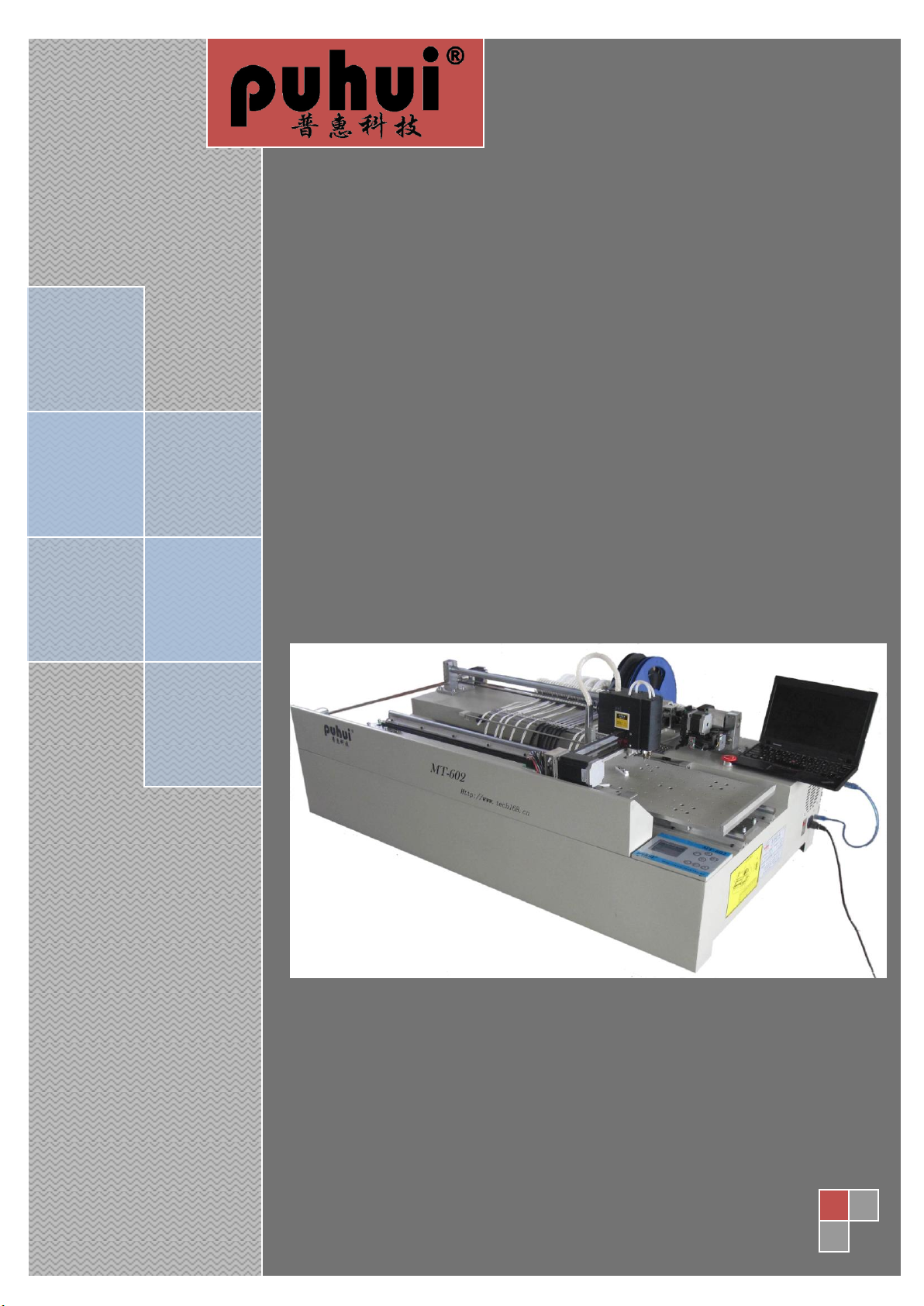
MT-602
User manual
Auto Chip Mounter
Taian Puhui Electric Technology Co., Ltd
Http://www.tech168.cn
Page 2

MT-602 user manual
Item
specification
product name
auto-mounter machine
product type
MT-602
mounting head
double mounting head
average speed
5000CPH
positioning accuracy
0. 025mm
net weight
151kg
applicable elements
0603-1206 SMD transistors, diodes, capacitors, resistors, chips, etc.
number of rack
56:8mm=50,12mm=4,16mm=2
Number of offline storage files
20
max size of circuit board
300mm×400mm
power supply
220V,50/60Hz,280W
vacuum gas source
-50Kpa,13L/min
operating system
Windows
installation dimension W×D×H
1396*761*480
Number of vacuum pump
2
Number of pump
1
malfunction detection
Suction leak detection, pressure detection
Instruction of installation and commissioning
Introduce of machine
一、 machine parameters
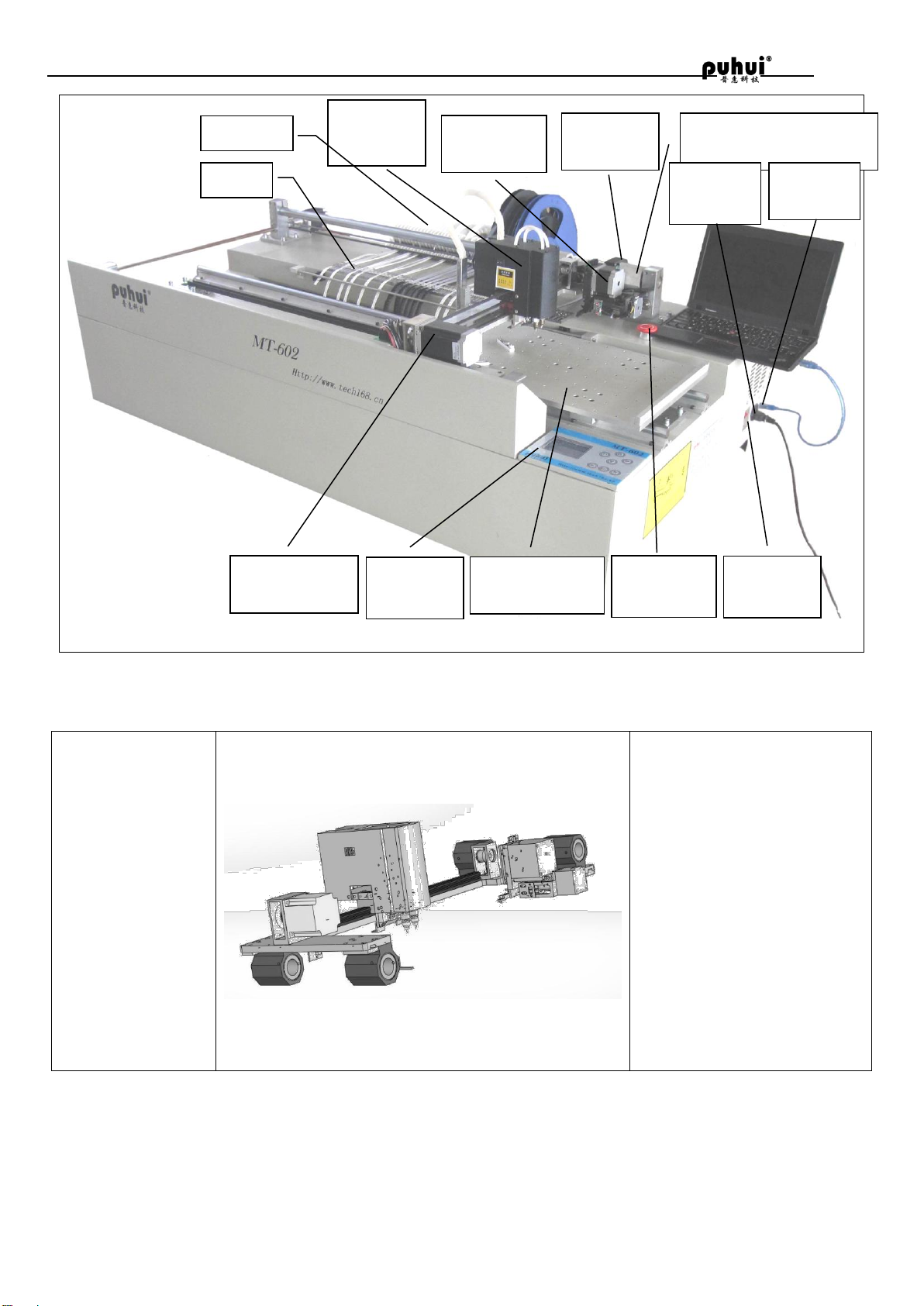
二、 appearance of the machine and basic structure
1 / 32
Page 3
MT-602 user manual
Y-axis motion
components
1, Y-axis plate
2, linear bearings supporting
base
3, linear bearings LM25UU
4, Y synchronous wheel
mounts
5, Y synchronous wheel
6, Y-axis motor mount
7, large X-axis belt fixed tooth
plate
8, shaft belt adjustment block
9, large X-axis belt adjustment
block briquetting
F608ZZ flange bearings
Emergency
stop switch
Suction
mechanism
Pusher
mechanism
Tray moving
mechanism
Feed tray
rack
Operation
panel
Y-axis motion
components
Power
switch
Take belt
mechanis
Rack shaft Motion
components
power
interface
USB
interface
三、 Main Institutions
2 / 32
Page 4
MT-602 user manual
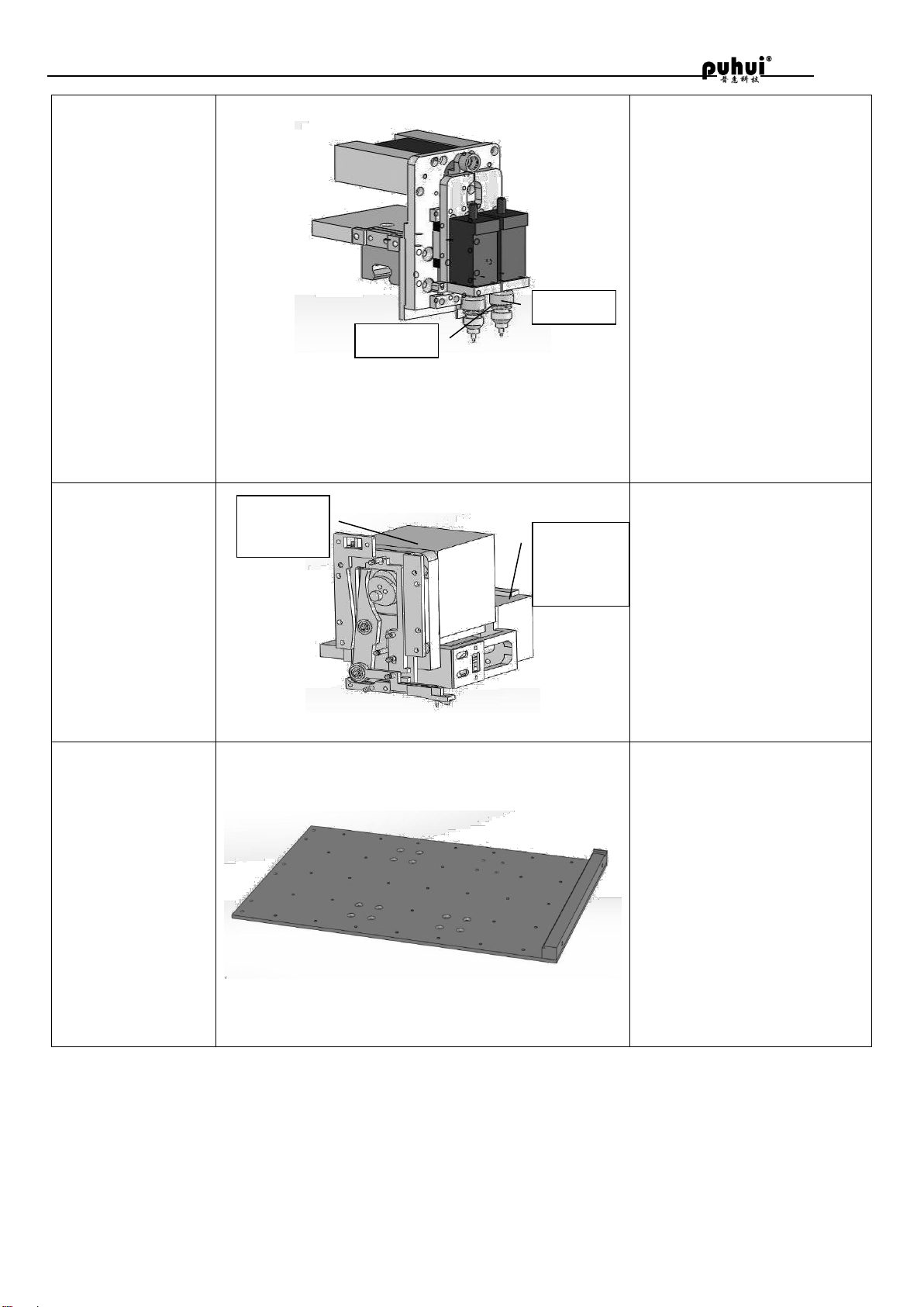
Suction
mechanism
1, the vacuum solenoid valve
2, linear slide MGN9C
3, Z-axis limit switch
4, pick-and-place the drive
motor Z
5, the rotary drive motor Q1,
Q2
6, a nozzle, the nozzle
assembly 2
7, Z-axis suction mounting
plate
8, Y-axis slide mechanism
connecting plate suction
9, Y-axis belt tensioning block
10, Y-axis belt tooth plate
11, motor angle slider stopper
Pusher
mechanism
1, the pusher motor
2, the pusher cam mechanism
component
3, T limit switch
4, the pusher pin
5, the pusher adjustment motor
6, pusher holder
7, pusher slider
Tray moving
mechanism
1,470X300 tray
2, the slider tray
3, the tray belt fixing plate
4, linear slide SBR16UU
5, slider slider
6, the right tray stopper
7. Fixed slider block
Nozzle1
Nozzle2
Pusher
motor
Pusher
adjustment
motor
3 / 32
Page 5
MT-602 user manual
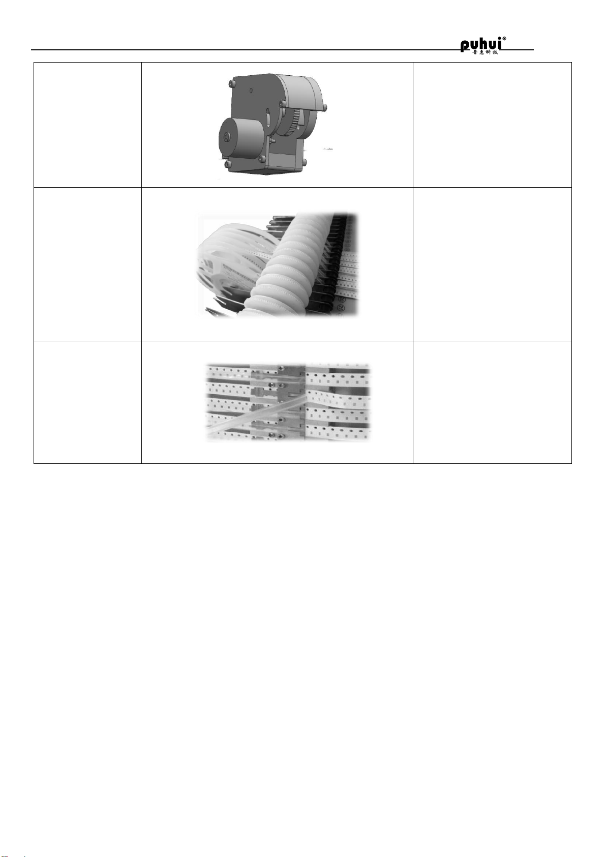
Waste recovery
mechanism
1, closing with gear box
2, the take-up gear assembly
3, take-up motor
4, the take-up motor drive
circuit board
Feed tray
1, tray holder
2, pin for tray
3, waste recycling gear
4, the guide wheel
Rack
1、patch wedge
2、pressing reed
3、discharge pressure bar
1. Preparation and Precaution of installing
(1)Preparation of installing
1. Choose a flat ground to ensure that the machine level
2. Choose firm placement platform to ensure that the machine can not move.
3. Enough space for production operations.
4. Avoid hot and humid environment.
5. Check the power cable if there is breakage.
(2)Precaution for use
1. Electrical Considerations
Use a multimeter to check if the power supply voltage is correct and the connection is reliable.
Ensure that it is earth grounded safely.
Ensure that all hardware connections are secure.
2. Safety Precautions
Before moving the machine, turn the power off, unplug the power cord.
Pay attention to personal safety when transport.
Ensure there is no foreign matter inside of machine before electrifying.
Preparation and installation
4 / 32
Page 6
MT-602 user manual
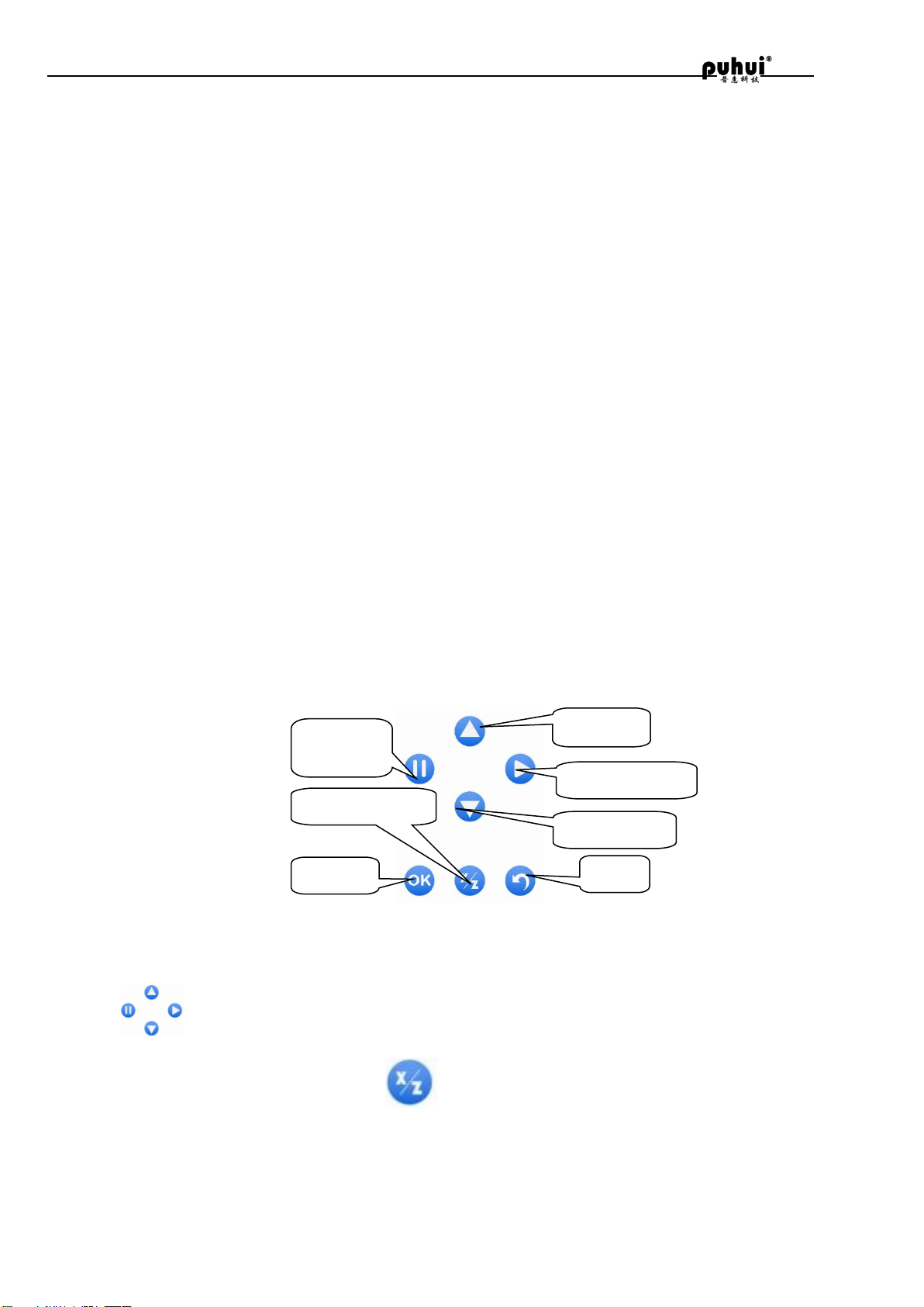
Cursor up
Back
Confirm
Mount Continue
Mount
pause
Cursor down
Tray in and oput
Before electrifying, manual confirmation of the agencies operating normally, without hindrance.
Press the red emergency stop switch, and the system power supply is disconnected when there is
emergency.
Installation of mounter
(1)Select the appropriate operating space for placing Mounter
(2)The SMT machine should be placed in a special support frame.
(3)The machine power should be accessed on the labeled INPUT socket.
Debugging Preparation
1. Safety tips of commissioning test
(1)All of components that are working should not be obstructed when operated.
(2)All of components that are working should not be pushed when stopped.
(3)Ensure that the terminal connection is well.
(4)Restart it after 20 seconds when cut off power.
(5)Press the red emergency stop switch and the system power supply is disconnected if there is emergency.
2. Introduce of operation panel
(1)Above panel
1. Emergency stop switch
Press this switch, power is cut off and all actions of mountor machine are stopped. Clockwise rotation,
button bounces and power is on, following that machine resets and each axis return to the original position.
(2)Main panel
1. LCD
2. Buttons
Description of function keys:
control the moving of mounting head. When the reference point to identify the state, it is uesd for
controlling the nozzle’s up and down movement, while other states, functions as shown above picture.
(3)Side panels
1. Cooling fan outlet
2. Access outlet for main power
When the reference point to identify the state, it is used as the arrow key of mounting head to
5 / 32
Page 7
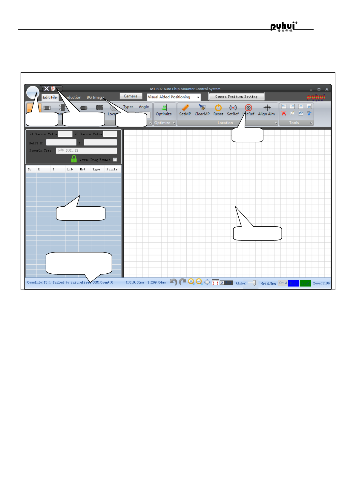
Main interface
Graphing area
Prompt area Status
Element list
Menu
Tab
Instructions
toolbar
3. Power switch
4. USB communication interface
3. Introduce of software interface
MT-602 user manual
6 / 32
Page 8

MT-602 user manual
Graphical representation
1. No directional element graphical representation 2. Directional element graphical representation 3. Transistor
element 4. Graphical representation of chip components 5. Mark point marker graphic 6. Reference Point logo
graphic 7. Circular array
1
2
3
4
7
5
6
Blue elements using nozzle 1
Green software uses nozzle 2
7 / 32
Page 9
MT-602 user manual
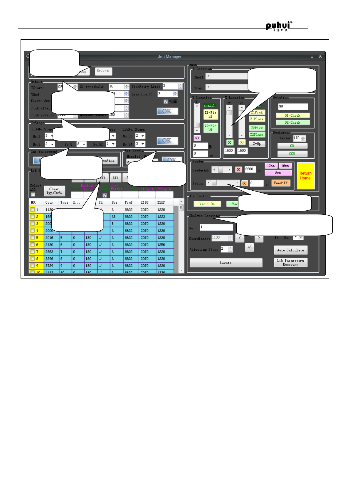
Parameter interface of equipment
Rack parameter
field
Backup and
recovery zone
Each axis positioning
zone
Rack coordinate adjustment
Other parameters
zone
Pusher step zone
Pneumatic control zone
Rack management
zone
Current nozzle
settings area
8 / 32
Page 10
MT-602 user manual
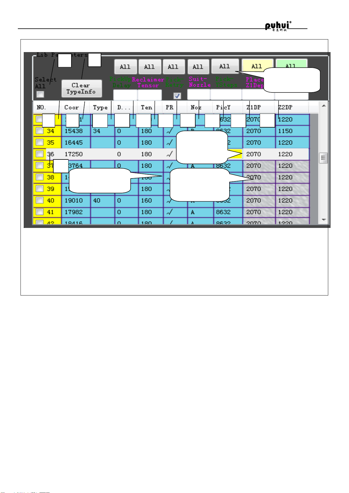
Interface of the device parameters
1. select all of rack 2. Empty rack model column 3. rack Number 4. device coordinates of rack 5. element
models of rack 6stay time on elements when picking element. 7. take-up tension of take-up belt 8. Whether
to check leak of rack element 9. The nozzle type that can be used on rack element. 10. device location
coordinates the feeder element Picking Y 11. Discharge depth of the rack-mount device application when the
nozzle 1, 12Discharge depth of the rack-mount device application when use nozzle 2, 13. Single rack selection
box
Blue area is
editable area
Gray areas is
non-editable
regions alone
yellow area is
current editing
area
2 1 3
5
4
6
7
8 9 10
11
12
Batch edit of
feeder parameters
13
9 / 32
Page 11
MT-602 user manual
Paraments interface of the device
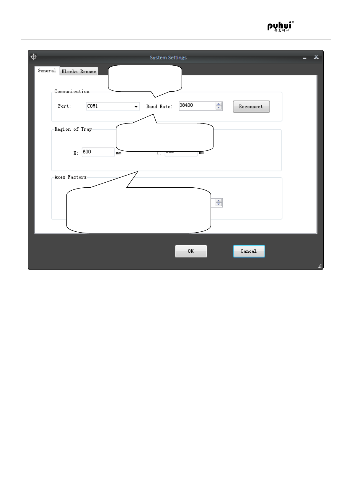
Rack coordinate coefficient correction: This
section generally do not need to change, but after
replacing a timing belt or adjust belt tightness
need to re-adjust
Mounter online port
selection
Communication baud rate
setting: Do not change this
10 / 32
Page 12
MT-602 user manual
Operation instructions
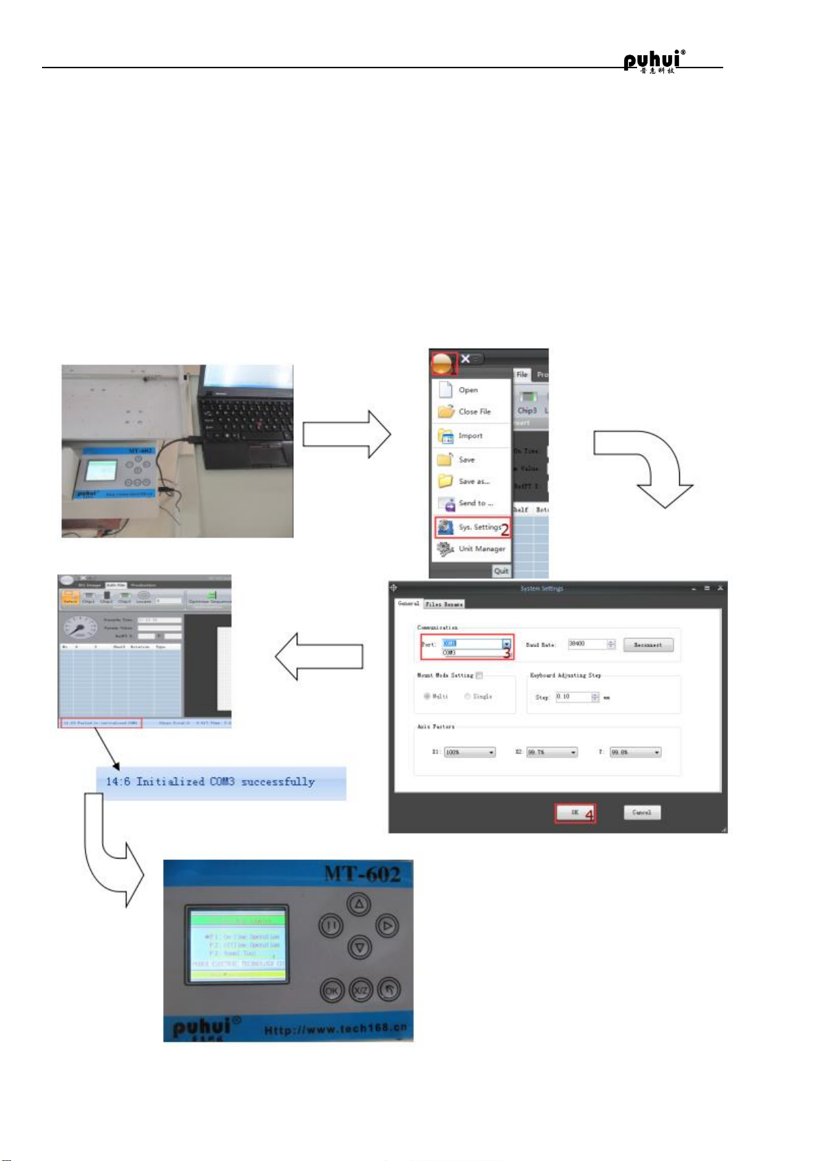
Operation 1 —— Connect with computer
一、Connect MT-602 with computer by using USB wire,open the control software, turn on the
power of MT-60.
二、Click “main menu” - “system parameter, you will see “system parameter setting dialog box”,
click serial port, you will see the current name of the serial port.
三、Select the serial port which match with USB wire.
四、Click OK, you will see the notice information in the bottom left corner of page。
五、At this time, Press “OK” at MT-602 operation panel, start to connect with computer, it connect
successfully when MT-60 operation page show “already connected with computer”
11 / 32
Page 13
MT-602 user manual
Operation 2 —— Parameter Adjustment
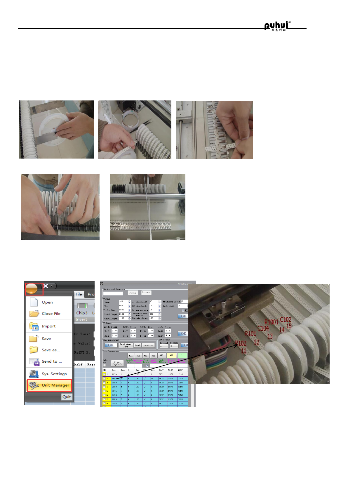
1. Install Feeders
Feeders NO 1-10 suit for diode, triode with plastic feeders. 31-34 suit for
12mm components,35-36 suit for 16mm components. The others suit for 8mm components.
2. Entry formation of feeders
(1). Click Main menu - Unit manager, entry the information of feeders.
12 / 32
Page 14
MT-602 user manual
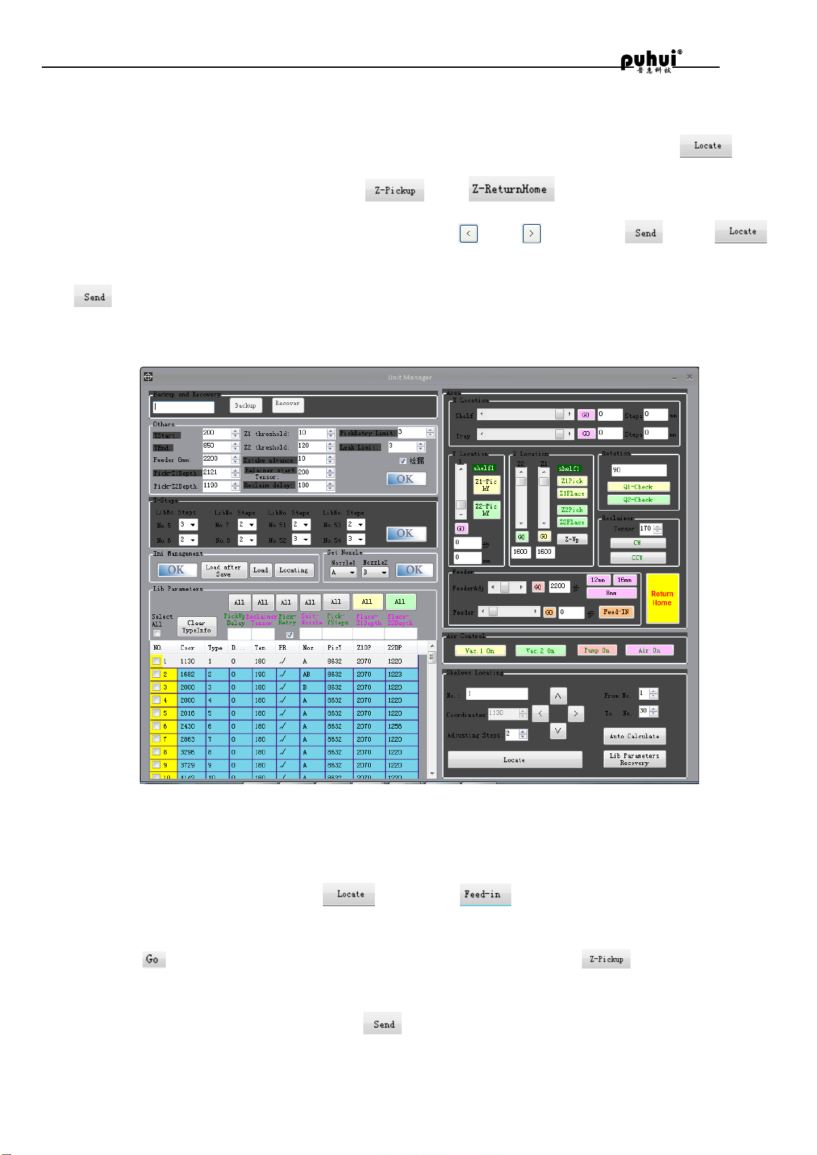
(2). Check feeders coordinate
Checking purpose: make nozzle locate in the middle of component between left and right.
Click “main menu” – “Unit manager”, click the number of checked feeder, click , the
nuzzle will move to the feeder, click and , check whether the nuzzle
locates in the middle of component. If not, click and , then click , click
again, the nuzzle wiil move the new coordinate, check again to confirm the position. Click
after adjusted.
(3). Check pick- Y steps
Checking purpose:make nozzle locate in the middle of component between before and after.
Select any a feeder number, click , then click to push a component, coil the skin
manually. Then copy the data of Y steps.
Click , the nuzzle will be moved over the component. Click , the nuzzle lands
on the component, check whether the nuzzle locates in the middle of component. Copy the
data to entry the pick Y steps. , click to save data.
13 / 32
Page 15
MT-602 user manual
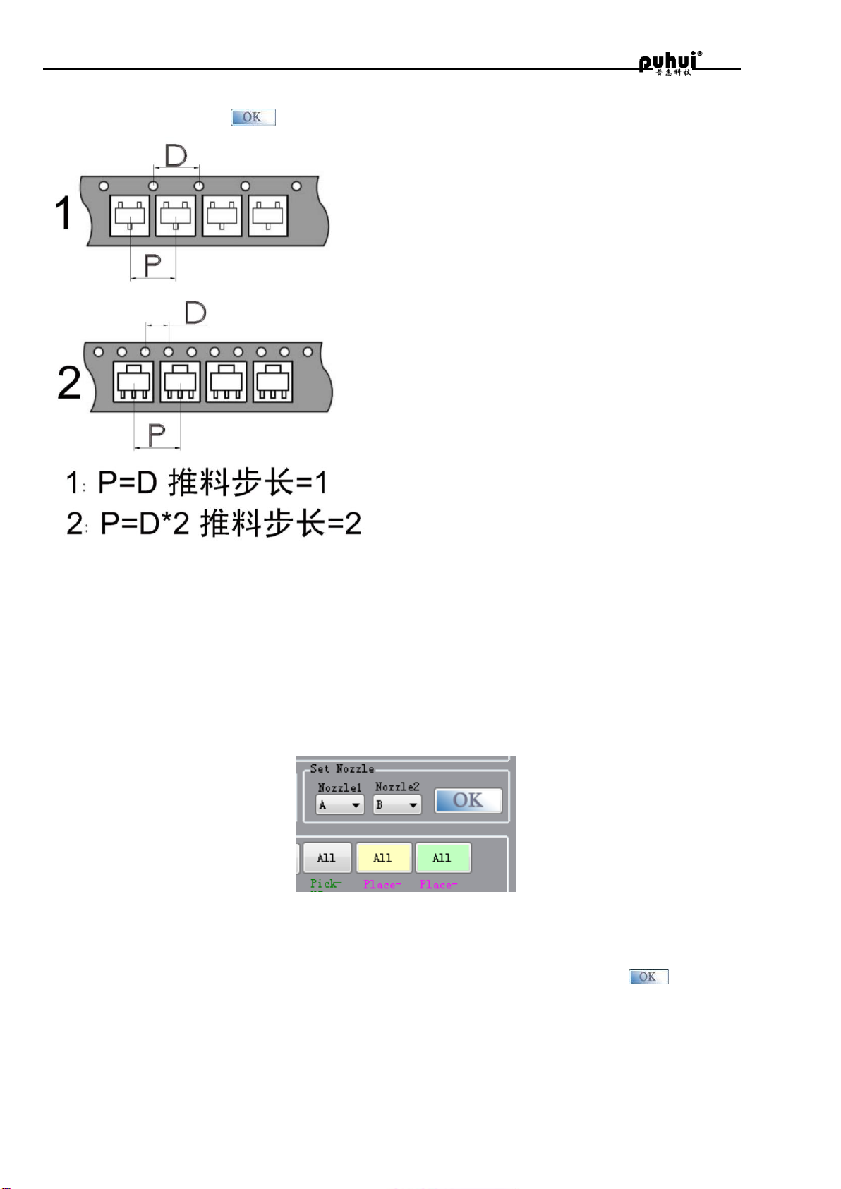
(4). In pushing step length, according to the no. 31 ~ 36 loading of material situation, set up
pushing step, click set after the completion of the pushing step to save data.
3. Suction nozzle setting
(1) The machine is equipped with five different specifications of the suction nozzle, specifications
and codes are: A inner diameter is 0. 6 mm, B inner diameter is 0. 8 mm, C inner diameter is 1. 2
mm, D inner diameter is 1. 5 mm, E inner diameter is 2. 5 mm. In order to realize the customer's
different specifications of the ideal of the patch SMT.
(2) Users choose to maximum meet all of the SMT components installed on the material shelf two
suction nozzle assembly requirements, installed on the suction nozzle 1, the suction nozzle 2.
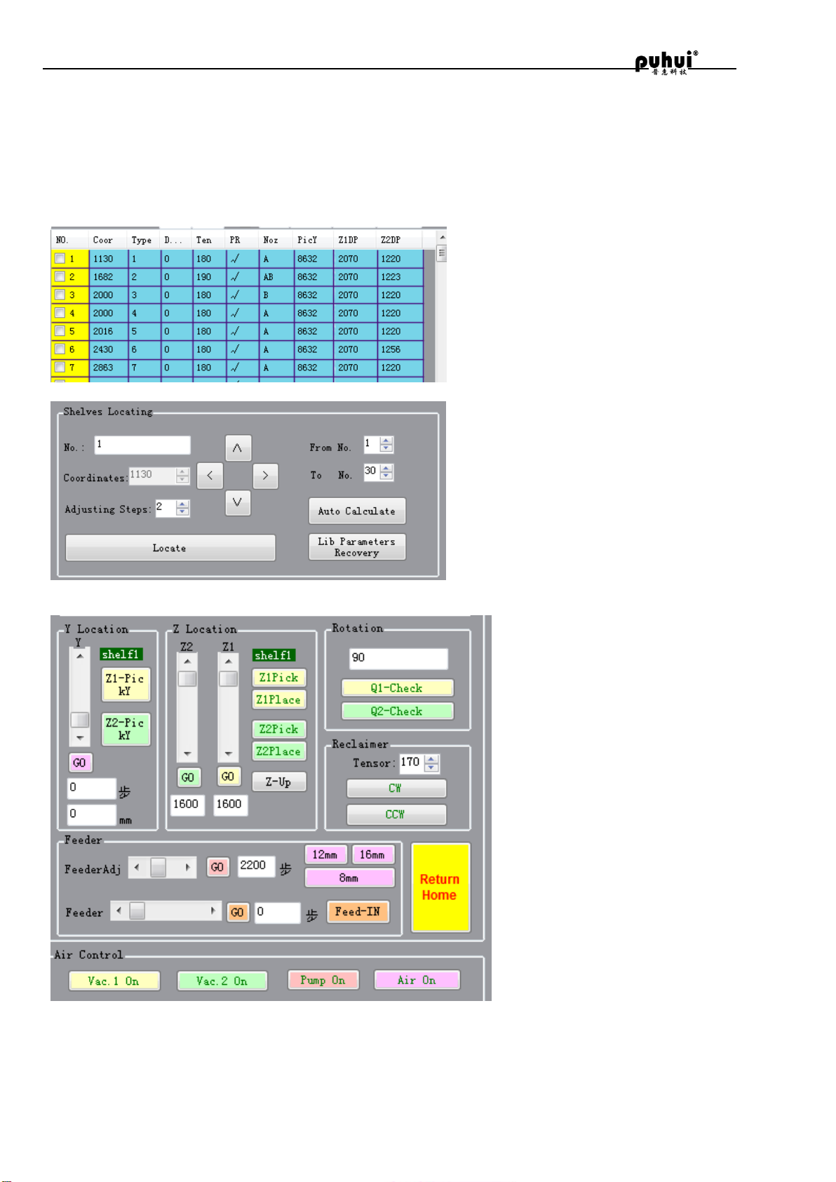
(3) Click the main menu - equipment parameters - in the "current suction nozzle set" drop-down
menu Settings, such as, code-named B of suction nozzle is installed on the suction nozzle 1, as
shown below "suction nozzle 1" below the menu option "B", the same method for the suction nozzle
2 "Settings, set up is completed, click the current setting suction nozzle area save data.
(4) According to the material on the element size set the suction nozzle. Of no. 0603
components using A suction nozzle SMT, 0805 and 1206 components using A and B, suction
nozzle specifications for SMT, large size chip components suggest using D, E, suction nozzle for
SMT. All other components according to the size to choose suitable for placement of the suction
nozzle specifications.
14 / 32
Page 16
MT-602 user manual
4. Parameter adjustment
(1) Coordinate correction and pick up material depth adjustment
▲ adjustment purpose: suction nozzle is located in the rack to head is the central element direction
and depth has the right to pick up.
▲adjustment method:
15 / 32
Page 17
MT-602 user manual
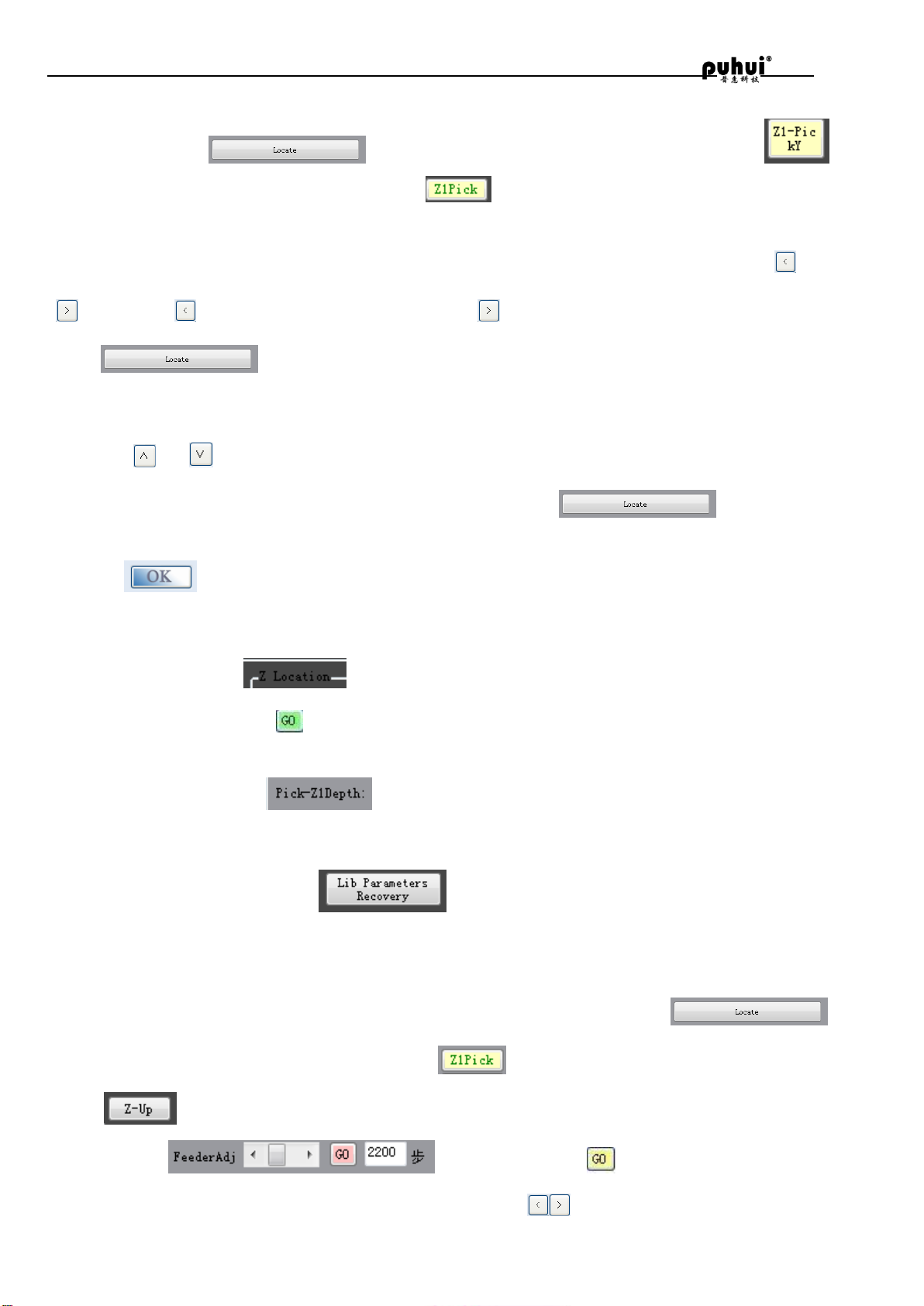
(1) In turn, click on the main menu - equipment parameters, the material parameter selection a
marking bar, click , suction nozzle 1 will be shifted to the rack, click ,
near the suction nozzle to the material, click on the suction nozzle 1 to fall on the
components, observe whether suction nozzle 1 is located in the center position of the element left
and right. If there is deviation, according to the migration direction and distance, click or
adjust (click , rack position shift to the left, click , rack position moves to the right). Then
click on the suction nozzle 1 will be moved to the new coordinates, repeating
observation adjustment, until the suction nozzle 1 is the central element is located in the left and
right.
(2) Click or button, will change the selected material (position number increased to shift to
the left, position number reduced to moves to the right), click , suction nozzle to
the material. Repeat the first step of the operation, until all rack position adjustment.
3, click on the material management, to save parameters are adjusted to the MT - 602
hosts.
4, watch suction nozzle in the above check Z1 falls on components, whether to have enough buffer.
If need to adjust, click on the main menu - equipment parameters, fine-tuning area Z1
slider and Z1 slider below , click to view at this time whether there is enough to the suction
nozzle on the element of the buffer, adjust the appropriate after copying the value in the text box
below the Z1 notification to the text box at the back, the same method to adjust Z2
found material depth (note: Z2 to pick up the smaller depth, said the whereabouts of suction nozzle
Z2 depth, the greater the Z1 pick up material depth, the greater the said Z1 falling depth is larger).
5, If parameter tuning out, press , material parameters all returned to the factory
settings.
(1) The adjustment of pushing mechanism
First in the material parameters of the bar, choose a 8 mm rack, then click ,
suction nozzle will be shifted to the rack, click
and , when the element suction nozzle 1 is located in the center of the left and right
position, slide the slider and click , pushing electric opportunity
to the slider move in the direction of the translation, click at the ends of the slider and then
16 / 32
Page 18
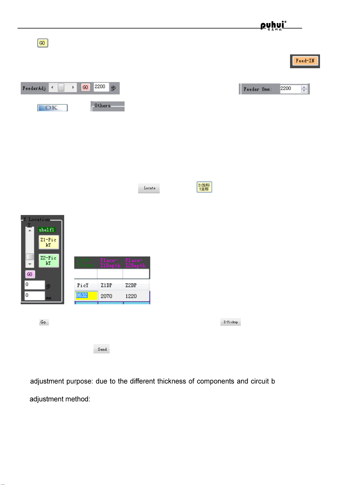
MT-602 user manual
click on pushing the motor position fine-tuning, when pushing motor to pushing needle at strip
pushing round hole left and right in the middle of the position, stop the adjustment, click
right now, to see whether the normal launch patch element, adjust the value
in ideal will be copied into the text box ,
click in the to save data.
(2) Check pick - Y steps
Checking purpose:make nozzle locate in the middle of component between before and after.
Select any a feeder number, click , then click to push a component, coil the skin
manually. Then copy the data of Y steps.
Click , the nuzzle will be moved over the component. Click , the nuzzle lands on the
component, check whether the nuzzle locates in the middle of component. Copy the data to entry
the pick Y steps. , click to save data.
(3) the feeding depth adjustment Feeding depth of ± 10 will have obvious change
oard thickness,
adjust the that suction nozzle feeding with appropriate flexibility.
1, 11 ~ 30 rack and 37 ~ 56 material feeding depth adjustment Will be pasted on the circuit board
fixed on the tray, Y axis adjustment slider, X axis, the slider, the suction nozzle above 1 to circuit
board. Adjust the Z1 slider, suction nozzle 1 after falling and circuit board, the distance between 1
after falling to suction nozzle, it is advisable to contact with the circuit board just. Copy Z1 slider
17 / 32
Page 19
MT-602 user manual
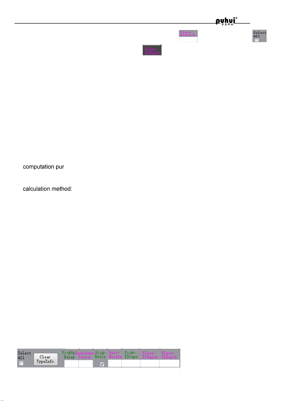
below the values in the text box, paste into the text box below and select material
to full box full frame materials, click on the button , the material of the Z1 feeding depth are
set to the values in the text box. To adjust the feeding Z2 depth in the same way.
In the no. 2, 1 ~ 10 aircraft and 31 ~ 36 material feeding depth adjustment
Rack and 31 1 ~ 10 ~ 36 rack for components have different thickness difference is bigger, so I
need a single material. Will be pasted on the circuit board fixed on the tray, will adjust the rack
components placed on the circuit board, Y axis adjustment slider, X axis, the slider, the suction
nozzle above 1 to components. Adjust the Z1 slider, observe the suction nozzle 1 after falling and
the distance between components, with suction nozzle 1 after falling, and element just slightly
elastic contact is advisable. Copy Z1 slider below the values in the text box, paste to the material
parameters of the area to adjust the material feeding Z1 bar text box. The same method to adjust
the other rack and Z2 feeding depth.
3, the same method to adjust the feeding Z2 depth. All after the adjustment, click on OK and save
material in the material parameter bar parameters.
(4) Suction nozzle MARK point coordinate difference calculation:
poses:
Computing suction nozzle 2 relative to the suction nozzle 1 place in the X direction and Y direction
deviation, so as to determine the suction nozzle device coordinates of 2.
1, have a small flag stop right at the tray.
2, open the placement machine control software, click edit graphics - click on the "1" suction nozzle,
the mouse moved to the lower right graph area, the cursor into a black cross style.
3, move the mouse or press the direction key (keyboard to adjust the interval is inversely
proportional to the magnification of the canvas, canvas magnification, the greater the keyboard
adjustment interval is smaller, the adjustment precision is higher. Sliding the mouse wheel to
zoom the canvas size), and makes the suction nozzle 1 corresponding move over the tray. Press
the space bar, SMT machine suction nozzle 1 will fall, loosen the blank space key and suction
nozzle 1 is raised.
4, use the mouse or the direction key to adjust the suction nozzle position, until the suction nozzle 1
center is for us to do MARK, press the Enter key, the cursor position MARK will appear blue cross
point MARK. At this point, "suction nozzle 1" behind the two text box will show the MARK point
coordinate values.
5, click on the "suction nozzle 2", the choice we make marked as benchmark, use the mouse or the
direction key to adjust the suction nozzle position 2, until the suction nozzle 2 center right we do
MARK in the block center, press the Enter key, the cursor position MARK will appear blue cross
point MARK. At this point, "suction nozzle 2" behind the two text box will show the MARK point
marker coordinates, press the ESC key to exit the MARK point positioning, suction nozzle 1 and
suction nozzle 2 X and Y direction coordinate difference value is automatically calculated and
displayed on the back of the two text box, click the "OK", transferred to the SMT machine.
(5) other material parameter adjustment:
18 / 32
Page 20
MT-602 user manual
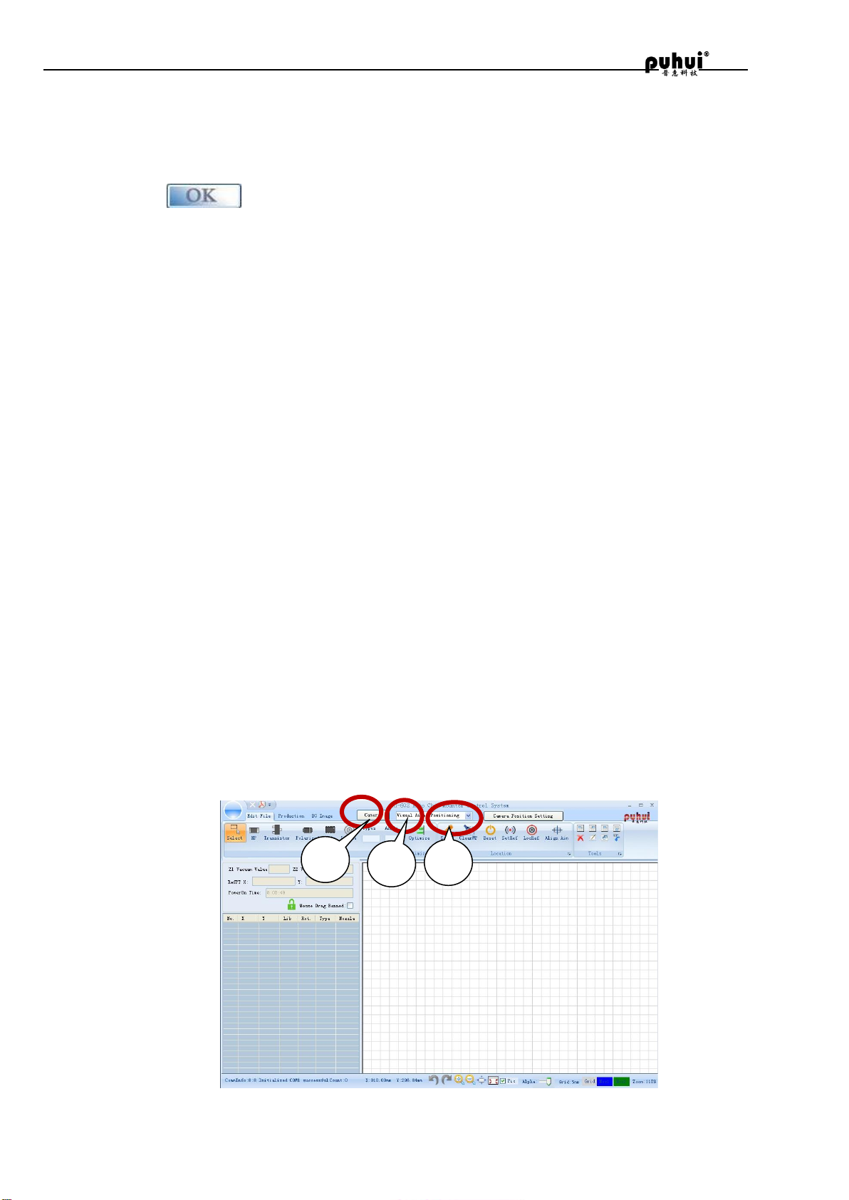
1 3 2
1, components are required when increasing material delay.
2, components of material coated hard to tear apart, tension, increase recovery of coated strip
break easily, reduce the tension of recycling.
Enable/disable 3, leak detection function.
4, adjust, click on the rack to save administrative zones
MT-602 visual aids
Main interface
19 / 32
Page 21
MT-602 user manual
Set enlarge
area
Window
set-top
Set parameter
Small
window
Enlarge
display area
Window
display/hide
preview
A B C
visual aids
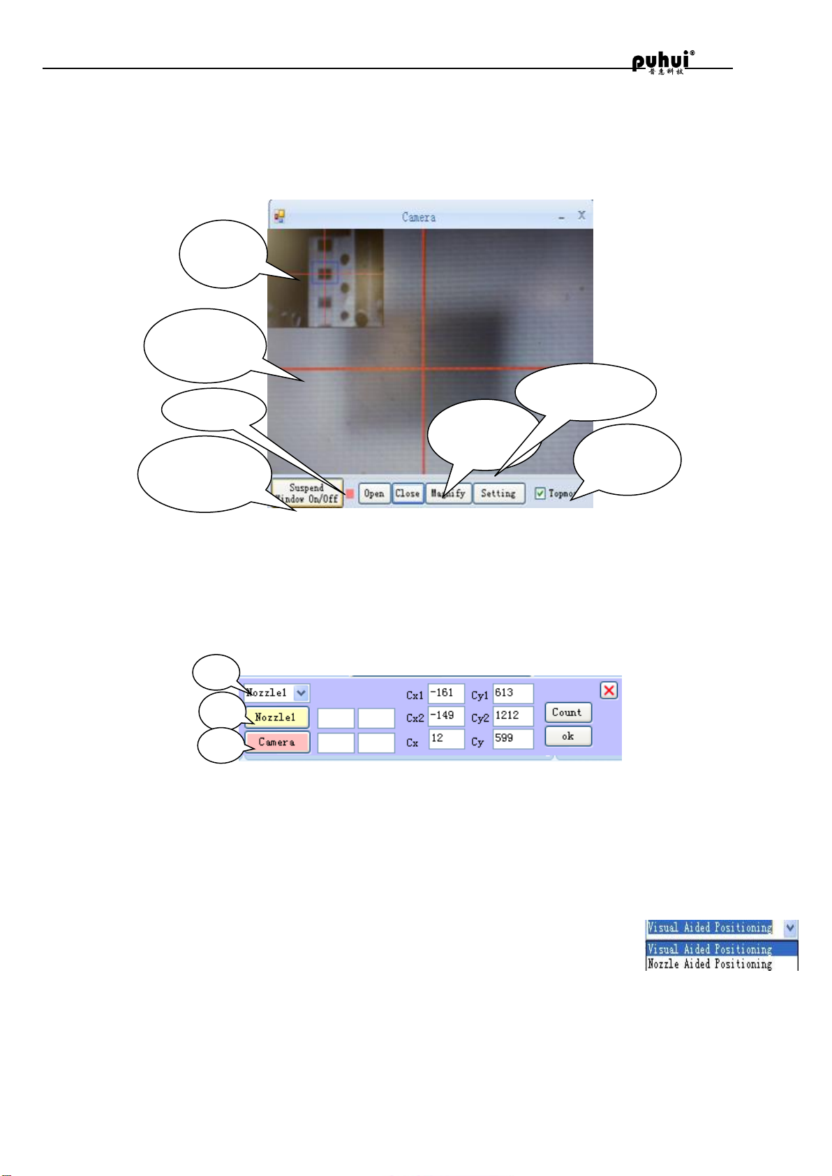
1 Click button 1 ,open visual aids
2 Use method of visual aids
(1)Click button 1 ,open camera。Visual aids will display image at small window and preview 。
(2)Click magnify,put mouse at small window ,choose a comment. it will display at enlarge area.
(3)The center of red cross is the center of camera。
(4)Using small window to make sure a general location ,make a accutate loctation at enlarge display.
3 (1) Poisition correction of Nozzle
Cx1. Cy1:poisition between Nozzle1 and camera Cx2. Cy2:poisition between Nozzle2 and camera
Cx. Cy:poisition between Nozzle1 and Nozzle2
Click 2 of main interface,open poisition correction of Nozzle. Click A change Nozzle1/Nollle2. Click
B/C ,set a Mark at
Same poisition,then will display a number at cx1 cy1 cx2 cy2 cx and cy. click Count,calculate the poistion
between at Nozzle 1 and Nozzle 2 ,click OK.
(2) Make sure the poisition correction of Nozzle, click 3 in main interface ,choose
Visual Aided Positioning to debug the correct position.
4 other description
We need reset the machine, afer changing the pattern the Nozzle or Camera to avoid wrong operation for
SMT machine machine structure
20 / 32
Page 22
MT-602 user manual
Operation 3 — Create placement data document
(Create coordinate )
1. Basic Operation
a. components edit
1). Place component
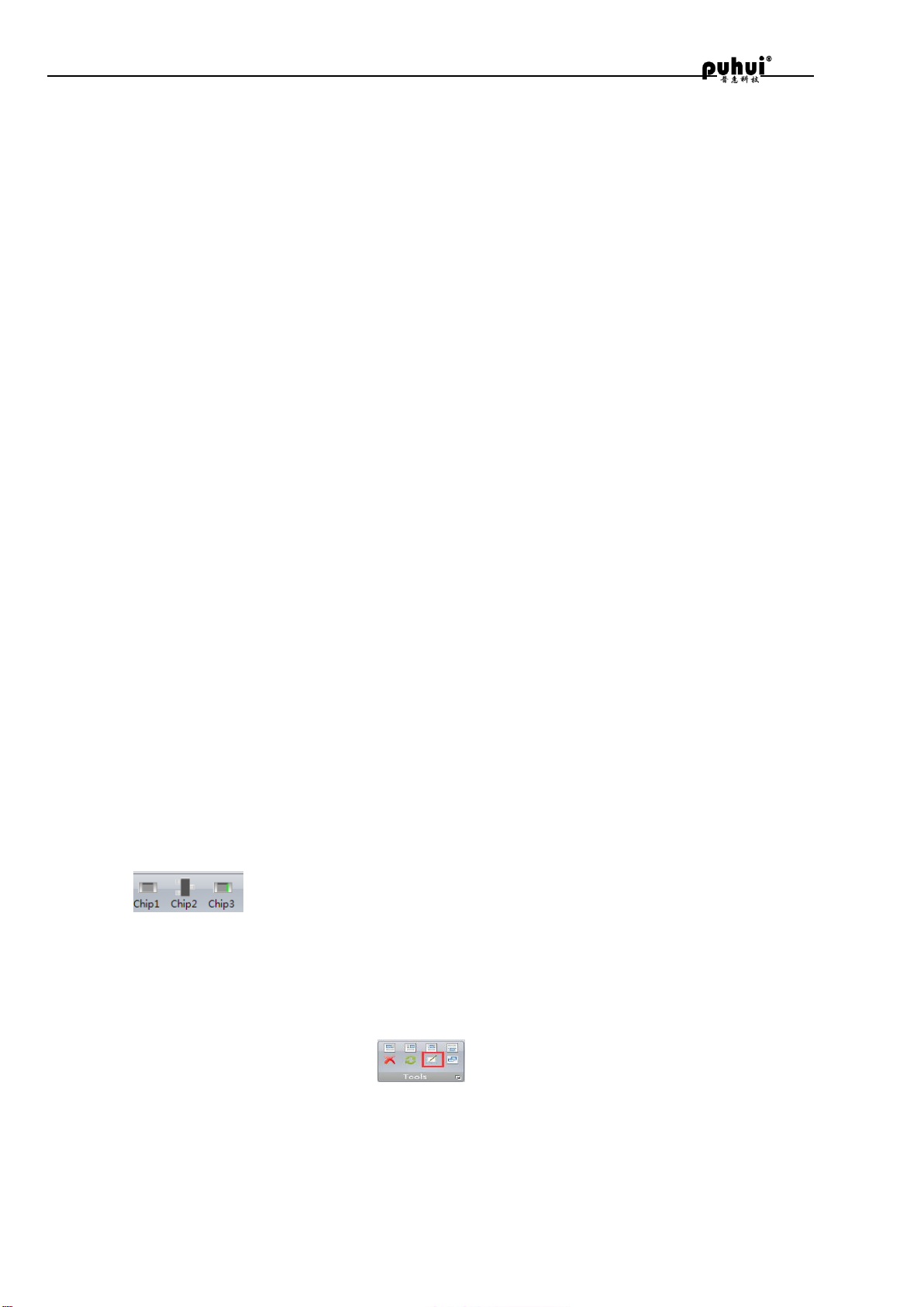
Click to choose a component type, click on the left side of the mouse for placing
component in the plot area.
Tips: press the space bar to change the direction of rotation before placing; press F2 bar to
change 90 degree of rotation. Click on the right side of mouse for quitting placing components
state.
2) Copy and paste
Select the copy components, click , select any component as the aim point, then
move mouse to the paste point, click mouse to finish.
b. Set mark point
Purpose: find the corresponding coordinate, which corresponds to one point of PCB in the plate.
Steps:
21 / 32
Page 23
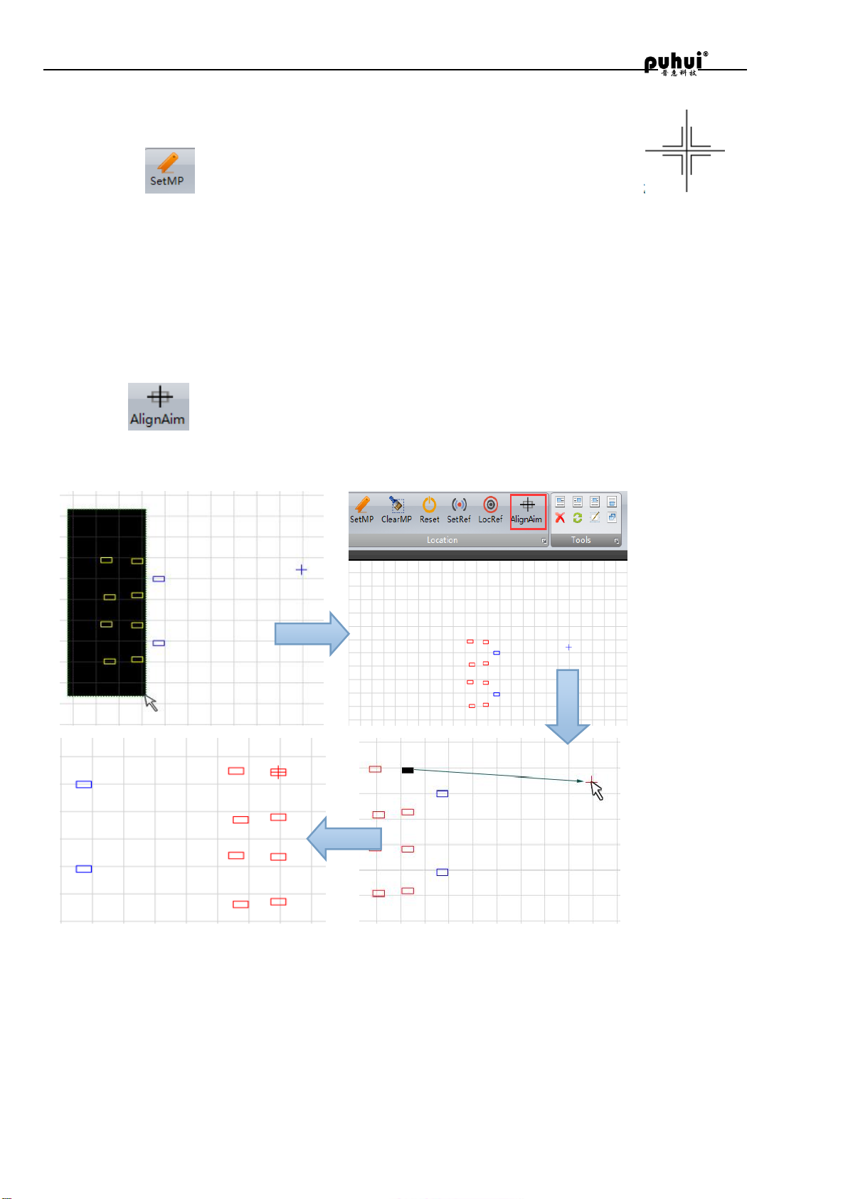
MT-602 user manual
1. Place PCB in the plate;
2. Click , move mouse to the plot area, the mouse pointer changes .
3. When move mouse or arrow keys, the nuzzle will be moved. Push the space bar, the nuzzle
lands on the PCB. Loosen the space bar, the nuzzle rises.
4. Select a component as aim component, move mouse to make nozzle land in the center of aim
component. Press Enter bar, the mouse pointer changes blue.
5. Press ESC bar to quit Mark state.
c. Align aim
1. Select all need to move components.
2. Click , click the aim component, it changes black.
3. Click the blue mark point, all the need to move components will be moved to the new area.
4. Press ESC to quit align aim state.
2. Create placement data document
There are 3 types to create placement data document. Mark every point, import PCB coordinate
document, Mark printer scan.
2. Create placement data document
MT - 602 can be used in the patch there are three kinds of coordinate data to establish a way: point
22 / 32
Page 24
MT-602 user manual
positioning entry, PCB file to import, scan location input, circular.
1, the MARK point positioning by component, the corresponding MARK tag elements, until all
components have the corresponding MARK points. (note: use the same suction nozzle)
2, in all the MARK point location place component.
PCB file output and format conversion (see MT - 602 automatic placement machine PCB file output
and format instructions. )
1, ready to scanner, circuit board, and image processing software
2, circuit board to be included in the scanner, as far as possible with scanner edge parallel, 1:1
scanning, will obtain the image into the computer. Using image processing software to upper and
bottom level, image rotation and the image of PCB image beyond the edge of the cutting, save.
3, open the MT - 602, click on the background image, click the insert pictures, find the image of the
second step, open.
4, hold the left mouse button over the image and drag the image to the upper right corner of the plot
area.
5, according to the position of each element in the image manually placed component, until all
components in place.
1, according to the situation of annular array to determine the reference element, element starting
Angle, circular starting Angle, the radius of the circular array and circular array element number.
2, in the plot area placed a polar components, Angle set component, hold down the ALT key and
double-click the component, on the "create element circular array" window, fill in the parameters,
click ok to generate the element circular array.
Component starting Angle: reference element of lines and the Angle between the horizontal line.
Circular starting Angle: the benchmark of connections between components center and the circular
array center of a circle with the Angle between the horizontal.
3. engineering data file is established
(a) makeup veneer patch data files. With reference to the first three ways.
(2) the MARK all single boards reference element corresponding MARK points.
(3) after all the components selected veneer, copy and paste. Repeated until the component
number consistent with makeup.
(4) select each veneer block elements, and with all single boards MARK point benchmark
counterpoint.
(5) repeat the step until all single boards MARK point center and the reference element.
(6)Click the main menu - save. Data files to establish completed.
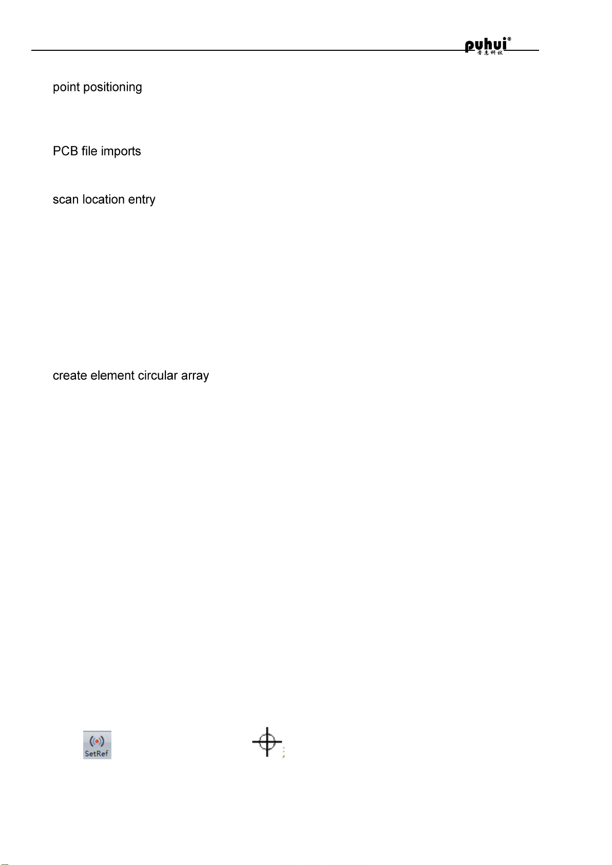
Operation 4— Set reference point
a. Mark point as the reference point of PCB in the plot area (via hole, pad holes, etc)
b. Click , mouse pointer changes ,click on the left side of mouse to set reference point.
c. Select the reference point, move to the mark point by align aim.
Operation 5—Entry information of component
23 / 32
Page 25
MT-602 user manual
machine status
Corresponding operation
The current tray
parts have not
been exhausted
Exclude the following fault,press for continue
1、 The component’ Pick coordinate is not modified.
(corresponding rack coordinate and corresponding rack’ Pick Y )
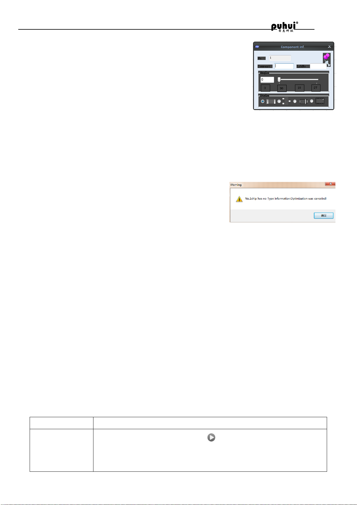
1 basic operations:
(1)Unit element editing
On the edit graphical interface---Graphing Area, double-click
the component and component parameter editing bar appears, you
can enter component parameters. Click the left mouse button on
the space allows component parameter editing bar disappears
(2)Multi-element edit
Make a note of the corresponding rack number for each
component and Select the same type of components(hold CTRL can select more),to input the
model corresponding rack number in text-box Under Toolbar--Types for all, and click Types For
All, this can modify component model in batch.
According to PCB, select the components having the same angle,to input target
component’ angle in Text-box under Angle For All of Toolbar , and click Angle For All, this way
can modify components’ angle in batch.
2 Improve patch data
(1)After finishing editing for all of patch, click optimize and
system will finish the match for racks and optimizing for patch
data
(2)After finishing optimizing ,to click SAVE in Menu,this way
can save patch data into computer.
(3)Click Menu-Transform, select Send to 0x in Dialog-Box(Mt-602 can save 20 kinds of patch
data and can work without computer. When transform, to avoid the document zine that had data,
or original data will be gone.
Operating procedures6------operate the mount file and produce
1 Run online
(1) Put the printed circuit board solder paste fixed on the tray holder according to the
established direction
(2)Open MT-602 control software and MT-602 main power to run online operation
(3)When successfully online, click Production--Run--Run document 0X, the machine will work.
(4)When mounter finished and reset, the next circuit board can be done
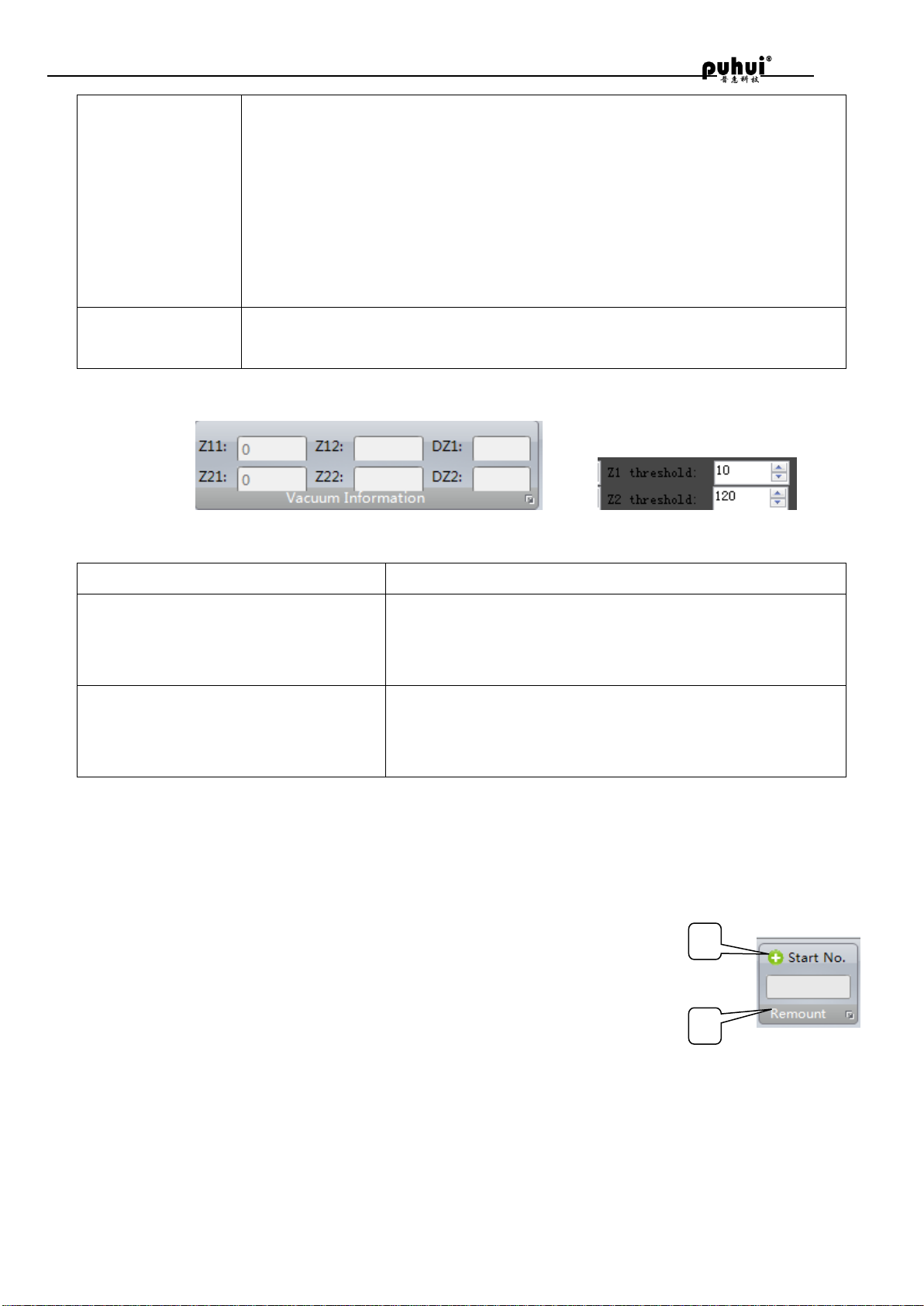
(5)Leak detection and set the threshold adjustment
Introduce of leak detection features
Mt602 could alarm and stop picking and placing of it can not suck the patch(component)
according to the set threshold. (menu--nuit manager--others--Z1 threshold/Z2threshold)
Check for leak detection alarm
If pop up leak detection hint, check the machine status and do the operations related to the
following table
24 / 32
Page 26
MT-602 user manual
2、 The component’ pick-depth is not right
3、 The component’ Relaimer Start Tensor is not right, cause cover
film on component can not be teared and it obstructs the
component to not be picked
4、 Nozzle type and component’s size is not matched, the diameter
of nozzle is bigger than component , which cause pressure leak.
5、 Z1/Z2 threshold is not right. Modify and reset threshold
The current tray
parts exhausted
Stop mounting, after replace new trays, to mount the next circuit or to
mount for trapping.
Machine Status
Corresponding setting
selection of nozzle type is properly
and drawing of element is right,
machine prompts leak
The Z1 / Z2 leak detection threshold is increased to a
value that is greater than the value of reported
leakage of DZ1 / DZ2
Component can not be picked and
machine can not alarm
The Z1 / Z2 leak detection threshold is increased to a
value that is smaller than the value of DZ1 / DZ2 when
mounting
2
1
leak detection threshold settings
According to the condition of pick for component and
Menu-Production--Information--DZ1/DZ2, to modify Unit Manager-Others--Z1/Z2 threshold.
trapping method for circuit board that leaked mounting
1. way of selection
Selection with Mouse:In the Run window or click the marquee to choose the subsidy
element needed
Input Serial Number: Enter the number on the text box showing on Picture2 and click on a
button, you can select all the elements from the beginning of the subsequent number
Mixed Selection:After use the way of Input Serial Number, you can use the
way of Selection with Mouse to increase or decrease elements
2. Trapping
After selection, you can click on trapping
25 / 32
Page 27
MT-602 user manual
MT-602 operation (not connect with computer)
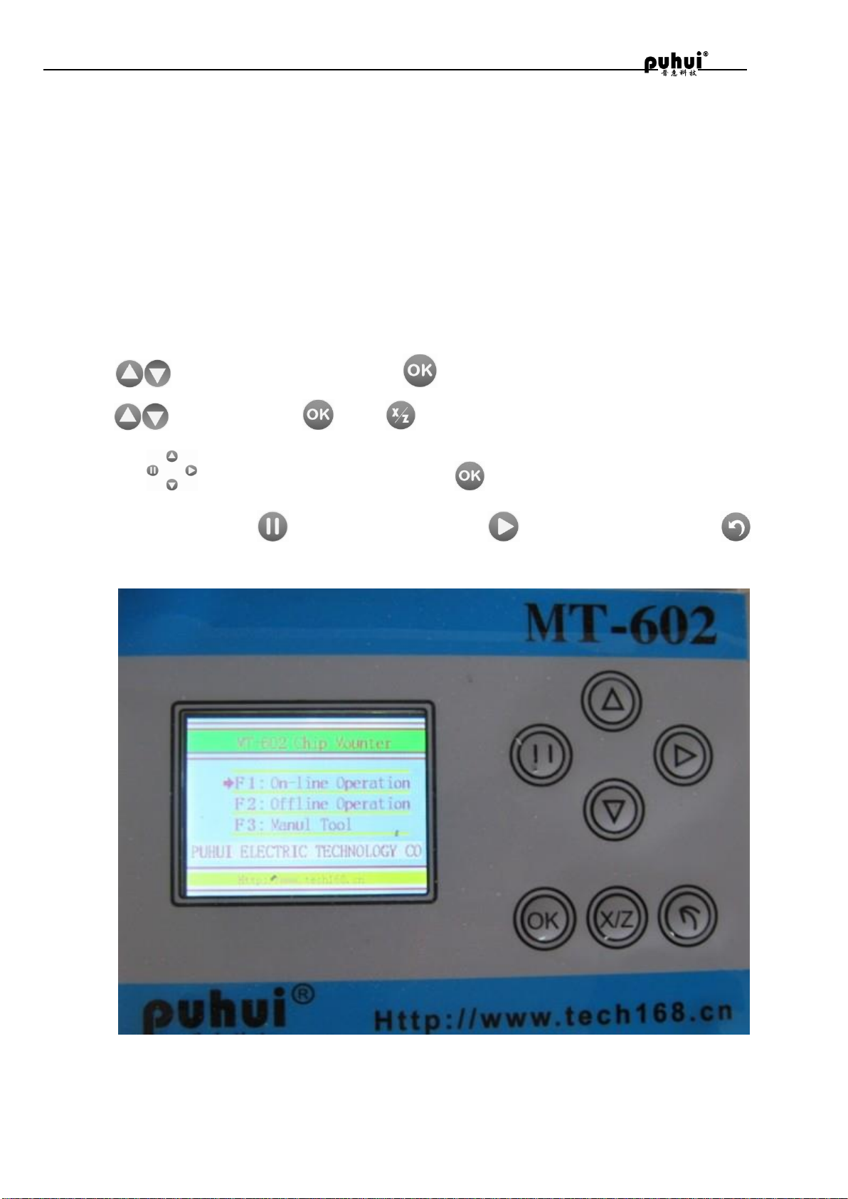
Production (Pick and Place)
1 Turn on the power
(1)Press to Offline operation ,press ,select placement file
(2)press ,select file,press ,press ,check if nozzle is in the center of reference point,
if not,press adjust nozzle in the center,press ,start mounting。
(3)When mounting, press to stop mounting,press continue mounting,press return
home。
26 / 32
Page 28
MT-602 user manual
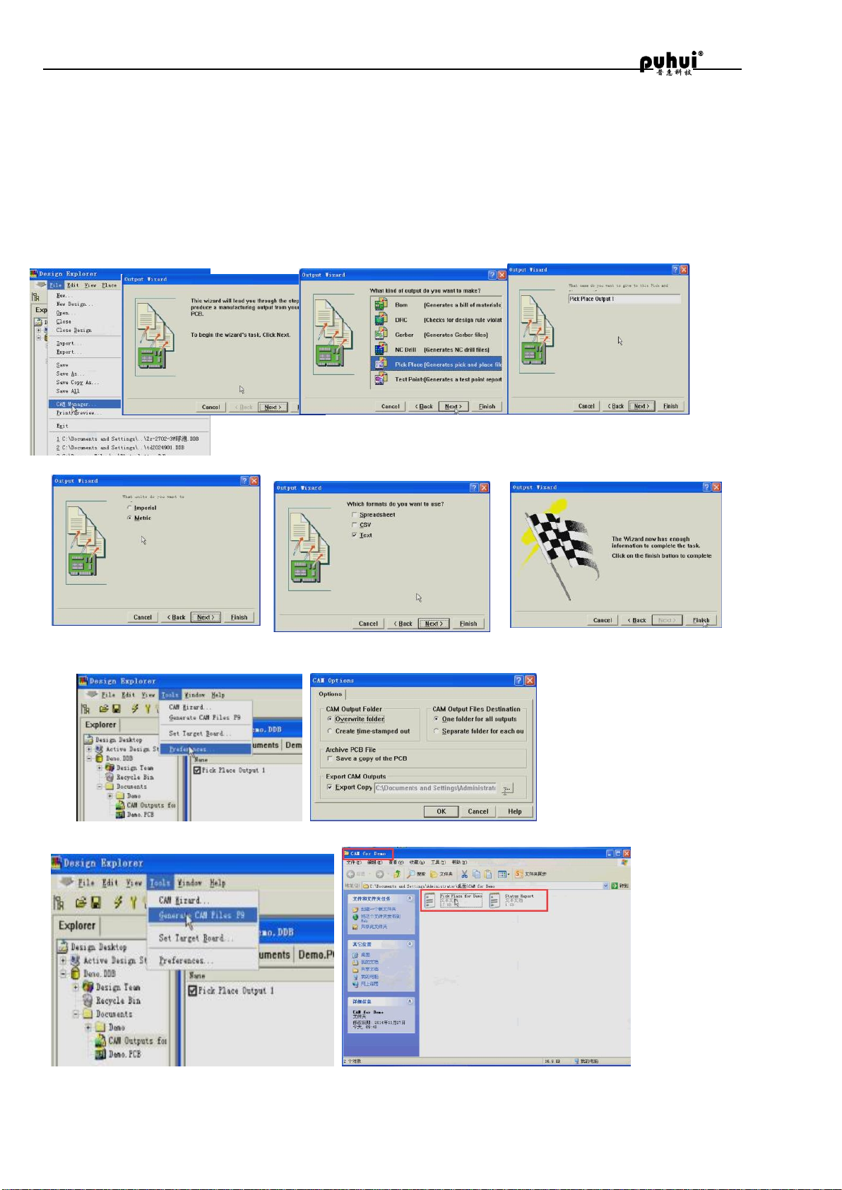
Create Pick & Place file (Protel 99SE for example)
1. Open the PCB file in Protel 99SE.
2. Click File-CAM manager-Next-choose “Pick Place”, then click Next-Next-choose CSV or Text,
then choose Next-Choose “Metric”, and then click Next-Finish.
3. Click Tools-Preferences-choose output path, then click OK.
4. Click Tools-Generate CAM Files, then it will generate a folder named CAM for **
27 / 32
Page 29
MT-602 user manual
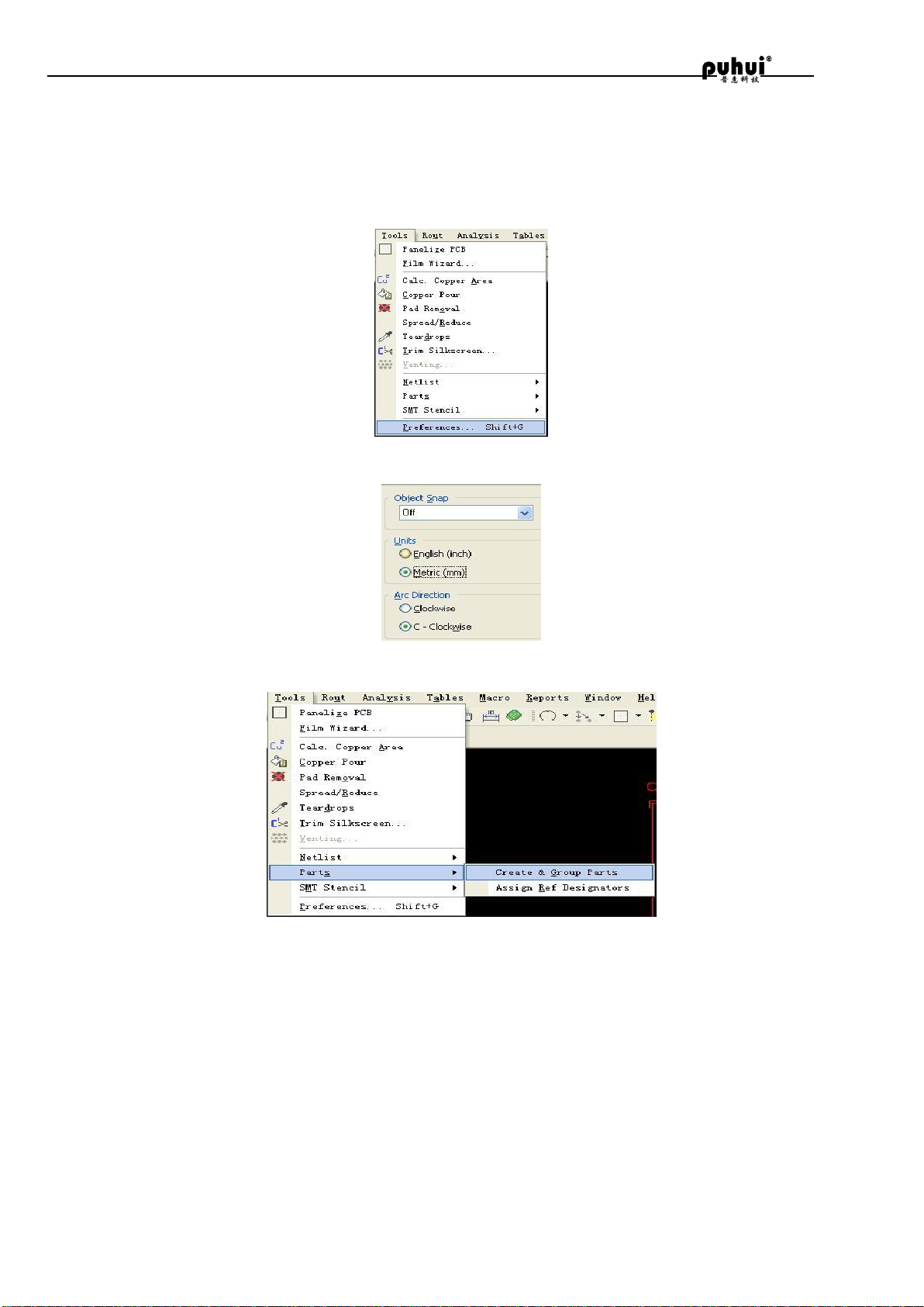
Using DXP output Gerber file
1 Open PCB file . GTS
2 Click menu bar(Tools)-choose Preferences。
3 Units choose Metric,OK .
4 Click menu bar Tools-Parts-Creat&Group Parts.
5 Click all welding plate include the components,click the right mouse button,show Assign/Group
Parts. Input component model at Description text box,input component angle at Rotation(Deg) text box.
Type choose SMT, OK. Choose the other components with the same method.
6 When all conponent edit over,click the right of mouse quit editing state.
28 / 32
Page 30
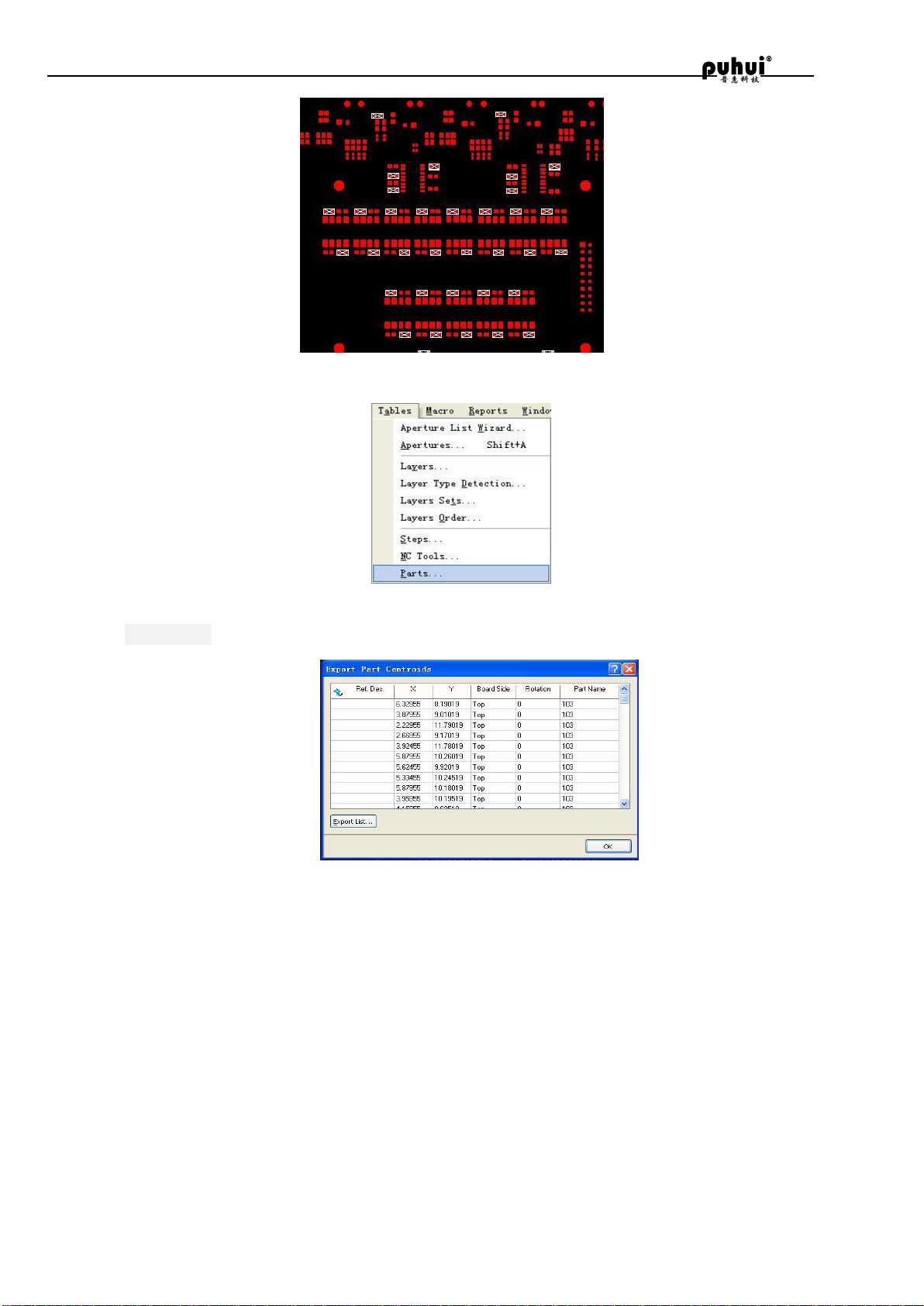
MT-602 user manual
7 Click menu bar Tables-Parts,show Export Part Controide .
。
8 Click Export List,show Write Centroid Parts window,choose the path of output,click OK.
Output . pcf file format.
9 Open the system of MT-602,click “menu”-”lead”,click “ open file”,choose . pcf file. Click “open”
“transform preview” “lead” creating . PH file.
29 / 32
Page 31
MT-602 user manual
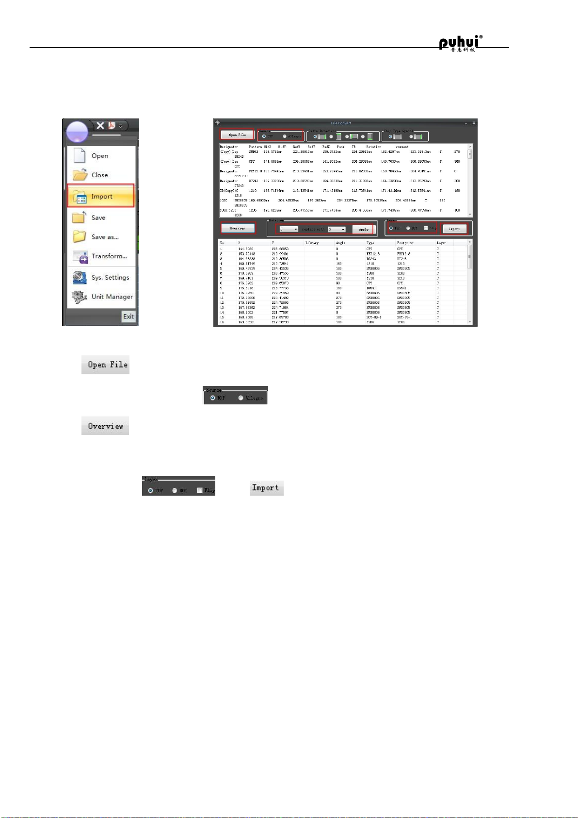
Import P&P file to convert for mounting machine
1. File the software of mounting machine, click main menu-import. You will see a pop-up dialog.
2. Click , choose P&P file to open.
3. choose output software model ,choose DXP generally.
4. Click .
5. For polarized components, 360° replace with 0°.
For unpolarized components, 180°replace with 0°,270°replace with90°, 360°replace with 0°
6. Select the layer , click . Components will be showed in the plot area.
7. Click main menu-save
30 / 32
Page 32
MT-602 user manual
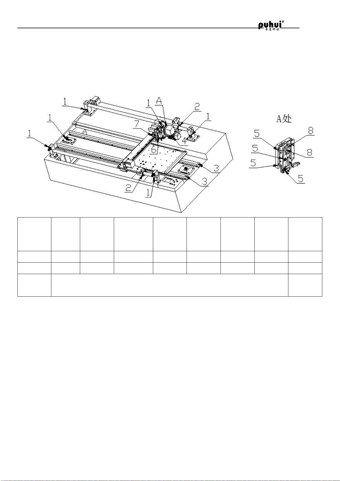
organiza
tion
608
bearin
g
LM25
line
bearing
SBR16
slider
LM8 line
bearing
619-3
bearing
9mm line
slider
15mm
line
slider
position
1 2 3 4 5 6 7
8
number
12 4 4 2 9 2 1
2
lubricant
lubricating oil
lubricatin
g grease
Maintenance
SMT machine maintenance and lubrication
chart
31 / 32
 Loading...