

Puch 1970-1971 Puch, 1970 Moped, 1971 Moped Maintenance Manual
PUCH
1970 and
1971
MOPED MAINTENANCE
MANUAL
Includes
• Technical Data
• Description
• Maintenance and service
• Trouble Shooting
Steyr - Daimler -
Puch
PUCH
SERVICE-AUSTRIA 907.1.71.033.1
i
PUCH-Motor-Cycles
mm
DESCRIPTION
AND
MAINTENANCE
STEYR - DAIMLER - PUCH AKTIENGESELLSCHAFT
AUSTRIA AUTRICHE
TABLE OF CONTENTS
1.
Technical Data
(see attached data sheet)
2.
Description
3. Maintenance and Service
4. Trouble Shooting
5. Index
V
FIRST READ — THEN DRIVE ! I !
Take this motto to heart and let your vehicle have that
minimum of maintenance and care it needs to give you
full satisfaction and security.
We present you therefore together with your new
PUCH MOTOR-CYCLE
these operating instructions.
The booklet is intended as an introduction to handling,
tending and maintenance of the vehicle.
Should it be your first motor vehicle, we advise you in
your own interest to read these operating instructions
carefully. Most damages are caused by ignorance and
hence could easily be avoided. Regular maintenance will
prevent troubles and repairs which may cost you much
time and money.
The section on trouble shooting will inform you about
many sources of faults. But do not undertake fumbling
things that can only be executed expertly by a reliable
workshop. A widespread service organsiation as well as
our own service department in the works at Graz will
be pleased to be useful to you.
When requesting information or ordering spare parts
please never forget quoting the engine number.
Numbers in brackets within the text refer to the illustrations.
Out of two numbers, the one on the left of the
oblique line indicates the numbers of the figure, the one
on the right of the oblique line refers to the numbers
within the figure.
Now we wish you a good start and a good time with
your PUCH motor-cycle!
STEYR-DAIMLER-PUCH
Aktiengesellschaft
VI
2.
DESCRIPTION
—.., ".-...... ....-—
H
7%
I
2.1
CONTROLS
Location and working of
the controls may be seen
from the data sheet hereto
attached.
2.2 FIRST PUTTING INTO
SERVICE
2.3 BEFORE EVERY TRIP
2.4 DRIVING
INSTRUCTIONS
2—1
2—2 DESCRIPTION
2.2 FIRST PUTTING INTO SERVICE
After final assembly, every PUCH motor-cycle has to
undergo a trial trip, it is therefore ready for use. It is
nonetheless strongly recommendable to carry trough the
following checkings before putting the vehicle into operation for the first time.
2.21 Comparing the charakteristic numbers
Before the first trip, compare the characteristic numbers
of the vehicle with those indicated on the registration
papers.
2.22 Checking the oil level in the gearbox
Are provided for the purpose either an oil control plug
or a dipstick on the right hand side gearbox cover.
a) Oil control plug version
(fig.
1)
With the vehicle in horizontal position (normal
posi-
tion),
oil level in gearbox should come up to the bot-
tom edge of the oil control plug
(1/2,
2a/2). In case
that mark is not reached, take off the oil filler plug
(1/1,
2a/l) and
fill
in motor oil (see section 3.21) until
oil comes out of the oil control hole. The oil control
plug (1/2) should be screwed in again only when no
more oil pours out of the hole.
b) Dipstick version (fig. 2)
Check oil level at horizontal (normal) position. Screw
out dipstick (2/1), wipe it dry and put it and pull
out again. Oil level is correct when between the two
DRIVING INSTRUCTIONS 2—3
marks.
If
oil level is under the lower mark,
fill
in
motor oil (see section
3.21).
If
oil level comes up to over the upper mark, loosen
oil drain
pliug
(2/2) and drain some oil. Before
measuring again, wipe the dipstick dry.
Whenever measuring oil level, screw in entirely the
dipstick!
2.23 Checking the air filter (for location see data sheet)
The intake muffler air filter must be wetted by motor oil
SAE 40 vor 50, except vehicles with dry air filter.
2.24 Checking the inflating pressure
For pressure figures see data sheet.
2.25 Gasoline-oil mixture refuelling
Mix gasoline with branded motor oil SAE 40 or 50 (See
lubricants chart) in a 1 : 25 ratio
(=
4%), that is 40 c.c.
on 1 liter of petrol.
Important! Never fill in pure petrol!
2.3 BEFORE EVERY TRIP
You should check:
0
Fuel provisions
9
Tyre inflating pressure
0
Braking efficiency
•
Lighting
•
Tool kit
2—4 DESCRIPTION
2.4 DRIVING INSTRUCTIONS
2.41 Starting the engine
0
Open fuel cock.
#
Put in ignition key (models with ignition lock).
%
Operate the choke only wen engine
cold,
if neces-
sary,
operate the tickler.
0
When re-starting a hot engine, do not operate either
choke notrickler.
0
In automatic models with pedals watch position of
change lever for treadle (see data sheet).
0
Open the throttle by 1A
(turn throttle twist-grip by one
third of its travel). Attention: in automatic models
open throttle only slightly.
0 In
automatic models with pedals pull lever for release
of starting device (see data sheet).
0
Crank engine by means of pedals or kick-starter.
0 In
case the choke has been operated, push in pro-
portion as engine warms itself up.
0
After a few hundred yards, the choke should be turned
off! (In case of a Bing-carburetter with
14
mm 0 and
17
mm 0, choke turnes off automatically by fully
opening the throttle
manentarily.)
2.42 Moving off (In automatic models just open throttle)
£
Pull clutch control lever; engage 1 st gear.
%
Release clutch lever slowly, simultaneously open
throttle twist grip.
2.43 Gear shifting (In automatic models results automatically according to number of engine revolutions)
DRIVING INSTRUCTIONS 2—5
The bottom gear which you are now using represent the
starting and climbing gear. As soon as circumstances
will allow, you will change up. Proceed as follows:
0
Throttle down.
#
Operate clutch control lever almost at the same time
and engage the next gear.
0
Release clutch control lever.
#
Open throttle.
After reaching maximum speed by fully opening the
throttle twist grip, throttle down to about 3A;
the fall in
speed will be hardly perceptible whereas fuel consumption will thus be considerably reduced. Throttle opening
should be turned to what the engine just needs-sharp
opening of the throttle twist-grip only increases fuel
consumption. When driving speed has to be reduced because of a slope or traffic circumstances, change down.
Proceed as follows:
0 If
necessary, apply the brakes and the same time
0
throttle back,
9
operate clutch control lever and change down,
0
release clutch control lever,
#
give throttle again.
Hint for owners of automatic models
When rapid acceleration requires even quicker gearshift-
ing,
throttle down completely after reaching about
25 km/h and open throttle again shortly afterwards. Thus
second gear shifted more quickly.
2—6 DESCRIPTION
2.44 Applying the brakes
Throttle back,
apply hand and foot-operated brake simultaneously. On
sandy, wet or slippery roads, use primarily the footoperated brake.
Always apply the brakes cautiously. Locking wheels
reduce the braking efficiency and entail skidding and
crashing.
2.45 Stopping and parking
#
Throttle back,
%
apply the brakes,
%
(Inapplicable in automatic models) just before stopp-
ing,
operate the clutch control lever and engage
neutral gear.
In
order to shut off the engine:
0
Press
short-circuiting
button. Pull out ignition key
(models with ignition lock),
%
shut fuel cock,
<0
shut off the vehicle.
2.46 Driving downhill
When driving downhill, the idling engine acts as a brake.
During longer descents, open the throttle every now and
then in order to grease the engine (the lubricant being
in the fuel). If necessary, apply the brakes. When des-
cending steep grades, engage bottom gear.
2.47 Treading with shut-off engine
(Possible
only in models with pedals, in automatic models with pedals
adjust change lever for treadle [see data sheet]).
DRIVING INSTRUCTIONS 2—7
0
Operate clutch control lever and engage 2nd gear
(3rd gear) whilst pedalling.
%
Mount the auto-cycle and set it going like a bicycle
whit pulled-down clutch lever.
%
Before stopping, engage neutral gear.
3. MAINTENANCE AND SERVICE
3.2 LUBRIFYING THE
VEHICLE
3.3 MAINTENANCE
OPERATIONS
3.4 CLEANING THE
VEHICLE
3.5 LAYING UP
3—1
3—2 MAINTENANCE AND SERVICE
SERVICE
A number of maintenance operations are beyond the
amateur's reach as he lacks the special devices necessary
for their execution.
We recommend therefore to entrust such operations to
one
of the many service stations set up by PUCH in
Austria as well as abroad. Their skilled personell dis-
posing of specially tested working methods and every
working facility will carry out any overhauling and repair
work rationally, economically and rapidly.
The PUCH-ORGANIZATION will always be pleased to
give you further information and advice.
SPARE PARTS
Correct and swift execution of all spares orders is
con-
ditioned by the exact quoting of chassis and engine
numbers and full type designation on the order form.
Below will be given a description of the recurrent maintenance works. The lubrication and maintenance schedules
will be found on the data sheet hereto attached.
LUBRIFYING
3—3
3.2 LUBRIFYING THE VEHICLE
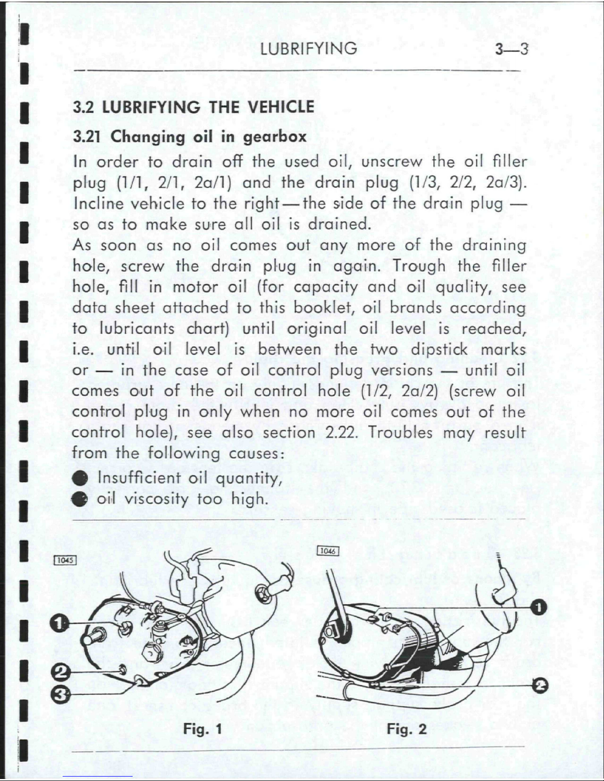
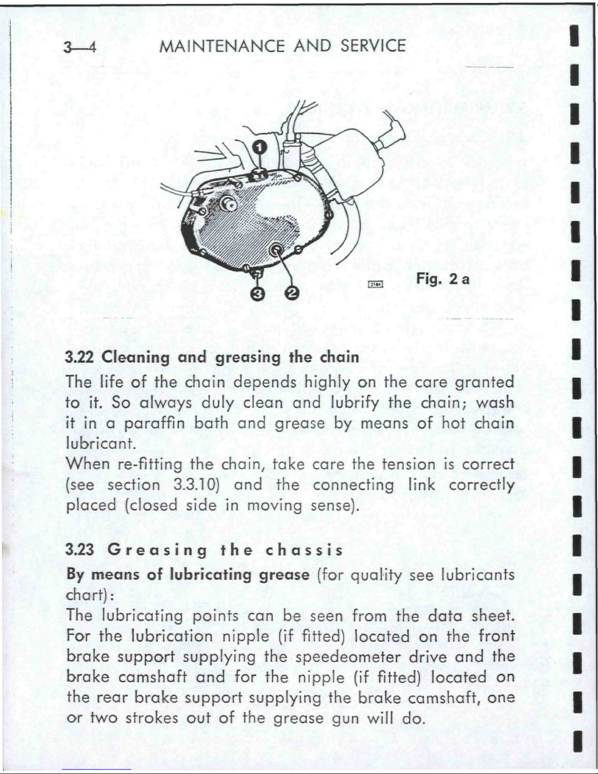
3.21 Changing oil in gearbox
In
order to drain off the used oil, unscrew the oil filler
plug
(1/1,
2/1,
2a/l) and the drain plug (1/3, 2/2, 2a/3).
Incline vehicle to the
right —
the side of the drain plug —
so as to make sure all oil is drained.
As soon as no oil comes out any more of the draining
hole,
screw the drain plug in again. Trough the filler
hole,
fill
in motor oil (for capacity and oil quality, see
data sheet attached to this booklet, oil brands according
to lubricants chart) until original oil level is reached,
i.e. until oil level is between the two dipstick marks
or — in the case of oil control plug versions — until oil
comes out of the oil control hole (1/2, 2a/2) (screw oil
control plug in only when no more oil comes out of the
control hole), see also section 2.22. Troubles may result
from the following causes:
0
Insufficient oil quantity,
%
oil viscosity too
high.
[ToSI
DwU
h
c~-
[
\
0
I
<>
©
3
€>
Fig.
1 Fig. 2
3—4 MAINTENANCE AND SERVICE
Fig.
2 a
3.22 Cleaning and greasing the chain
The life of the chain depends highly on the care granted
to it. So always duly clean and lubrify the chain; wash
it in a paraffin bath and grease by means of hot chain
lubricant.
When re-fitting the chain, take care the tension is correct
(see section 3.3.10) and the connecting link correctly
placed (closed side in moving sense).
3.23 Greasing the chassis
By means of lubricating grease (for quality see lubricants
chart):
The lubricating points can be seen from the data sheet.
For the lubrication nipple (if fitted) located on the front
brake support supplying the
speedeometer
drive and the
brake camshaft and for the nipple (if fitted) located on
the rear brake support supplying the brake camshaft, one
or two strokes out of the grease gun will do.
MAINTENANCE OPERATIONS 3-5
By means of lubricating oil (quality see lubricants chart):
0
Brake adjusting screw on front and rear wheel
0
Chain tensioning screws
#
Gearshift links and bearing points (if fitted)
4
Central prop bearing
#
Saddle bearing points (if fitted)
0
Brake pedal bearing
#
Working surfaces of brake and clutch control levers
#
Bowden cables (if necessary, take off headlight
bracket)
3.24 Changing oil in rear suspension unit and telescopic
fork
This operation should only be carried out — according to
the instructions given in the repair manual — by a
PUCH
service station (capacities given in the data sheet attached
to this booklet).
3.25 Lubrifying the grease felt supplying the ignition cams
Lubrify the grease felt by means of BOSCH grease
Ft!
v4.
The lubricant must not reach the
make-and-break
contacts
where it would cause excessive wear.
3.3 MAINTENANCE OPERATIONS
Entrust all works that you feel to be out of your reach
to a PUCH representative; he will be pleased to help
and advise you.
3.3.1 Checking the spark-plug
Screw the spark-plug out of the cylinder and hold it by
its threaded end against earth, e.g. the cylinder head
3—6 MAINTENANCE AND SERVICE
(plug
still
being connected with the plug wire). If the
starting device is now operated, a powerful spark should
flash over between the electrodes. Oily plugs or plugs
with dirt deposits between the electrodes will not pro-
duce any spark and must be cleaned (wooden splinter or
steel brush).
When replacing, only use a spark-plug whose thermal
value corresponds to the figure indicated in the data
sheet. The spark gap should be between 0,5 to 0,6 mm.
If
the gap is wider, regap by bending the outer elec-
trode.
When screwing the plug in, take care it
fits
well
into the thread and may easily be turned. Never have
recourse to force when screwing in: Screw in by hand
2 or 3 turns, only then you may use the spark-plug
wrench.
Standard plug according to data sheet.
3.3.2 Decarbonizing the engine
The constitution of deposits on cylinder cover, piston
head and exhaust port is a necessary corollary of the
working of our combustion engines (two-stroke engines),
but a length is a source of troubles. Combustion products originating from oil as well as from fuel must
therefore be removed from time to time.
Cylinder cover and piston head
Removing the carbon deposits from cylinder cover and
piston head must be carried out by means of a blunt
edged instrument (screwdriver or the like). As surface
hardness of light alloys is relatively low, their surfaces
may easily be scratched. Scratching is to be avoided as
every new scratch entails inevitably the constitution of
MAINTENANCE OPERATIONS
3—7
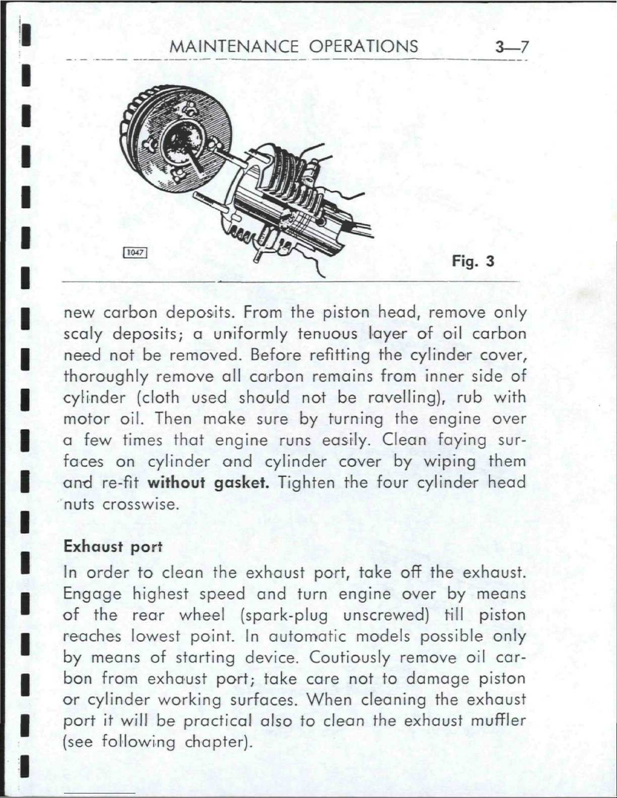
Fig.
3
new carbon deposits. From the piston head, remove only
scaly deposits; a uniformly tenuous layer of oil carbon
need not be removed. Before refitting the cylinder cover,
thoroughly remove all carbon remains from inner side of
cylinder (cloth used should not be ravelling), rub with
motor oil. Then make sure by turning the engine over
a few times that engine runs easily. Clean faying sur-
faces on cylinder ond cylinder cover by wiping them
and re-fit without gasket. Tighten the four cylinder head
nuts crosswise.
Exhaust port
In order to clean the exhaust port, take off the exhaust.
Engage highest speed and turn engine over by means
of the rear wheel (spark-plug unscrewed) till piston
reaches lowest point. In automatic models possible only
by means of starting device. Coutiously remove oil carbon from exhaust port; take care not to damage piston
or cylinder working surfaces. When cleaning the exhaust
port it will be practical also to clean the exhaust muffler
(see following chapter).
 Loading...