

Page 1
User Manual
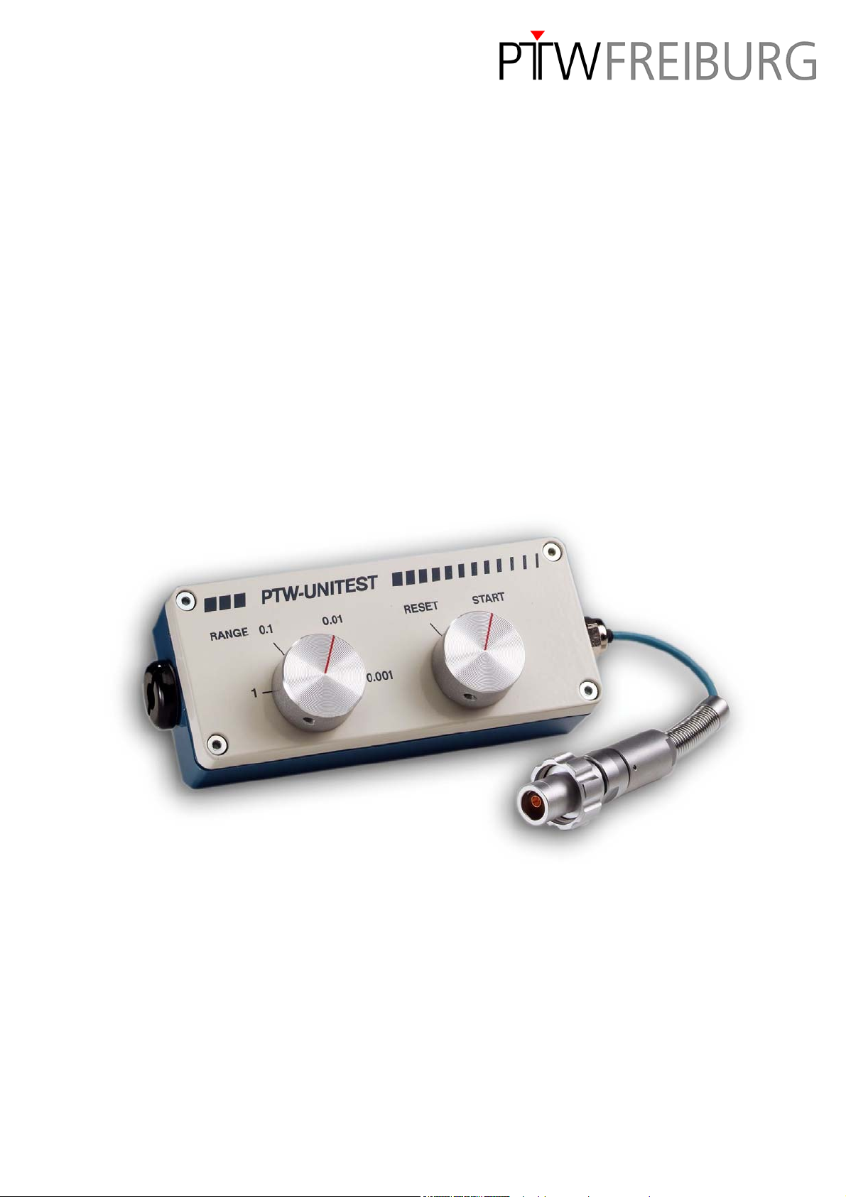
PTW-UNITEST
(Electrical Check Device)
Type 47001, Type 47002 and Type 47003
D235.131.0/4 2005-12 Sa
Page 2

General Information
PTW-UNITEST
(Electrical Check Device)
General Information
− The product bears the CE-mark "CE-0124" in
accordance with the Council Directive
93/42/EEC about Medical Devices and fulfills
the essential requirements of Annex 1 of this
directive.
The product is a class IIb device (MDD).
− The user manual is an integral part of the
product. It should always be kept near the
product. Observance of the manual is a prerequisite for proper product performance and
correct operation.
− Operator safety, specified measuring accuracy
and interference-free operation can be guaranteed only if original products and parts are
used. Furthermore only the accessories listed
in this manual are approved by PTW-Freiburg
and may be used in conjunction with the product, or else accessories whose use has been
expressly permitted by PTW-Freiburg. Safe
operation and proper product performance are
not guaranteed if accessories or consumables
from other manufacturers are used.
− This manual is in conformity with the product
specifications and all applicable safety standards valid at printing date. All rights are reserved for devices, circuits, techniques, software and names referred to in the manual.
− Electromagnetic immunity: The product fully
complies with the electromagnetic immunity
requirements of standard IEC 60601-1-2
`Electromagnetic Compatibility - Medical Electrical Equipment`.
− No part of the technical documentation may be
reproduced without written permission from
PTW-Freiburg.
− PTW-Freiburg works in strict accordance with
a quality management system which is continuously updated according to national and
international standards.
− PTW-Freiburg cannot be held liable for dam-
ages resulting from the use of accessories,
consumables from other manufacturers or
when the user ignores the instructions and information given in this manual.
− The warranty period is 1 (one) year and begins
on the day of delivery.
It is unaffected by repairs covered by the warranty regulations.
− PTW-Freiburg considers itself responsible for
safety, reliability and performance of the product only, if assembly, extension, readjustment,
modification or repair is carried out by
PTW-Freiburg or by persons authorized by
PTW-Freiburg, and if the product is used in
compliance with the technical documentation.
PTW-FREIBURG
Physikalisch-Technische Werkstätten
Dr. Pychlau GmbH
Lörracher Str. 7
79115 FREIBURG
GERMANY
Phone: +49 761 49055-0
Fax: +49 761 49055-70
info@ptw.de
www.ptw.de
2 D235.131.0/4
Page 3

PTW-UNITEST
(Electrical Check Device)
Contents
Contents
General Information 2
1 Intended Use 4
2 For Your Safety 4
3 Description of the Instrument 7
4 Description of Function 7
5 Measurements with the UNITEST 8
5.1 Hints for the use of the UNITEST 8
5.2 Preparing the measurements 8
5.3 Measurements 8
6 Evaluation of the measuring results 11
6.1 Consistency check of the response in the different measuring ranges 11
6.2 Electrical constancy checks 11
7 Cleaning, Maintenance, Disposal 12
7.1 Cleaning 12
7.2 Preventive Maintenance 12
7.3 Disposal of the Product 12
8 Technical Specifications 13
Literature 14
D235.131.0/4 3
Page 4
PTW-UNITEST
(Electrical Check Device)
Intended Use
1 Intended Use
UNITEST is an electrical check device for the surveillance of the PTW dosemeters listed in chapter 5. No mains connection or battery is needed to
operate UNITEST; it is simply connected to the
dosemeter instead of an ionization chamber. Using
UNITEST the following checks can be done:
− Check of the consistency of the response in all
doserate and dose measuring ranges.
− Electrical constancy check of the different ampli-
fier ranges and of the internal high voltage supply of the dosemeter.
It must be observed that the connection systems of
UNITEST and dosemeter are compatible. Use of
adapter cables is not permitted.
When the UNITEST is not in use, it should be
stored in a location protected against humidity. The
connector should be protected with a dust protection cap.
2 For Your Safety
The following safety statements are divided into
DANGER, WARNING, CAUTION and NOTE.
Definitions
DANGER
Indicates an imminent hazard. If not avoided,
the hazard will result in death or serious injury.
WARNING
Indicates a hazard. If not avoided, the hazard
can result death or serious injury.
CAUTION
Indicates a potential hazard. If not avoided, the
hazard could result in minor injury or product /
property damage.
NOTE
Provides useful information to assure that you
get the most from your equipment.
4 D235.131.0/4
Page 5
PTW-UNITEST
(Electrical Check Device)
For Your Safety
Safety Information
DANGER
Explosion Hazard – The product is not suitable
for operation in areas of risk where an explo-
sion hazard may occur. Explosion hazards
may be caused by the use of combustible anaesthetics, skin-cleansing agents and disinfectants.
Furthermore the product is not suitable for application in oxygen-enriched atmospheres.
The atmosphere is considered to be oxygenenriched when more than 25 % of oxygen or nitrous oxide is added to the ambient air.
WARNING
Shock Hazard – Strictly observe the following
warnings. Failure to do so may endanger the
lives of the patient, the user and other persons
involved.
− Before using the product, the operator must
ascertain that it is in correct working order
and operating condition.
− Before putting the device into operation,
visually inspect all connection cables for
signs of damage. Damaged cables and connectors must be replaced immediately.
− Devices on which moisture condensation
has developed as a result of temperature
changes must not be switched on unless
completely dry.
− Liquids must not enter the device. If liquids
have entered the device, it must be thoroughly inspected before being used again.
Exclusion of operation in the patient environment:
Neither the product nor any peripheral device
may be operated within the patient environment
(see Figure 1).
Exclusion of operation as device with patient contact:
The device is not for use in direct contact with
the patient. Neither UNITEST nor any peripheral device may have contact to the patient.
Never touch the patient and open connectors of
the device at the same time.
WARNING
Suffocation Hazard – Dispose of the packaging material, observing the applicable wastecontrol regulations. Keep the packaging material out of children's reach.
Patient Hazard – The product is a medical
electrical device and must only be handled by
persons who are trained in the use of such
equipment and are capable of applying it properly. The operator must be trained in the use of
the device.
Risk of Poisoning – Chemicals required for
application or maintenance of the device, for instance, must under all circumstances be stored,
prepared, and kept at hand in their specific
containers. Failure to observe this instruction
may result in severe consequences for the patient.
CAUTION
Equipment damage - Always observe the ambient conditions as indicated in the `Technical
Specifications`.
NOTE
Please observe the user manuals of all connected devices!
Set up the device so that the operator has a
clear, unobstructed view of the control panel.
D235.131.0/4 5
Page 6

NOTE
PTW-UNITEST
(Electrical Check Device)
For Your Safety
This symbol means:
Refer to user manual.
This symbol means:
Separate collection for electrical
and electronic equipment!
(refer also to section Disposal of
the Product)
This symbol means:
The product bears the CE-mark.
Figure 1: Definition of patient environment
6 D235.131.0/4
Page 7

PTW-UNITEST
(Electrical Check Device)
Description of the Instrument
3 Description of the Instru-
ment
The UNITEST has 2 control elements (see Figure 2):
Range switch
left selector switch to adapt to the measuring
ranges of the dosemeter (see Table 1)
Start switch
right selector switch for the injection of a charge
into the dosemeter.
4 Description of Function
The electrical check device UNITEST is working
with passive components. UNITEST does not need
a mains connection or a battery; it is using the high
voltage supplied by the dosemeter.
By putting the right selector switch of UNITEST into
START position, a capacitor on UNITEST is
charged and the charge is injected into the measuring input of the dosemeter.
In accordance with the measuring range to be
tested, the test current must be adjusted using the
left selector switch of the UNITEST. This is actuating a precision voltage divider in the UNITEST.
Figure 2: UNITEST front panel with the "RANGE" switch and the "START" switch
D235.131.0/4 7
Page 8

PTW-UNITEST
(Electrical Check Device)
Measurements with the UNITEST
5 Measurements with the UNITEST
5.1 Hints for the use of UNITEST
− Always connect the UNITEST directly to the
dosemeter. Do not use extension or adapter cables.
− Do not move the UNITEST or the connection
cable during measurements.
− Only use the UNITEST range selector switch
when the right UNITEST selector switch is in
RESET position.
− Check values are independent of the doseme-
ter's polarity setting. Dosemeter polarity should
only be changed in the least sensitive measuring
range and with the UNITEST disconnected.
5.2 Preparing the measurements
1. Switch on the dosemeter and wait for the duration of the warm-up time.
5.3 Measurements
1. Adjust the UNITEST range according to Table 1
(e.g. 0.001 when using it with a UNIDOS).
2. Start at the dosemeter a charge measurement
using the STA
sition the right UNITEST selector switch to
START. Do not move UNITEST and connection
cable.
3. After the test time given in Table 1, read the
measuring value and note it down.
4. Set the right UNITEST selector switch to RESET
position. The dosemeter should be in the next
higher measuring range and in RESET state.
When using UNITEST with UNIDOS in the
measuring mode "Charge" the RESET state of
UNIDOS must be selected first before the
UNITEST selector switch is set to RESET position.
or the MEAS button, then po-
2. Set the dosemeter to electrical units.
3. For dosemeters with variable high voltage adjust
a chamber voltage of 400 V; polarity is of no importance.
For measurements with the TANDEM adjust a
chamber voltage of 250 V.
4. Set the dosemeter to charge measurement and
measuring range Low.
(For measurements with the TANDEM, also see
the hints below.)
5. Set the right UNITEST selector switch to RESET
position.
6. Connect the UNITEST to the dosemeter. Do not
use extension cables.
7. Wait for about one minute.
8. Perform a zero adjustment.
NOTE
If a measurement must be repeated in the same
position, wait for about 20 s after switching back
to RESET position before starting a new measurement.
5. Repeat the steps 1 to 4 for all settings in Table 1.
CAUTION
During switching between the UNITEST ranges
the right UNITEST selector switch must be in
the RESET position.
8 D235.131.0/4
Page 9

PTW-UNITEST
(Electrical Check Device)
Measurements with the UNITEST
Dosemeter setting UNITEST range
Standard range of
Test time T
dosemeter display
values
UNIDOS
webline
Charge Low 0,001 (84 - 92) pC 10 s
Medium 0,1 (8,4 - 9,2) nC 10 s
High 1 (84 - 92) nC 20 s
UNIDOS
Charge Low 0,001 (84 - 92) pC 10 s
High 0,1 (8,4 - 9,2) nC 20 s
Integrated Current Low 0,001 (84 - 92) pC 10 s
Medium 0,1 (8,4 - 9,2) nC 10 s
High 1 (84 - 92) nC 20 s
UNIDOS E
Charge Low 0,001 (84 - 92) pC 10 s
Medium 0,1 (8,4 - 9,2) nC 10 s
High 1 (84 - 92) nC 20 s
MULTIDOS (Channel 1 and 2)
Charge Low 0,01 (840 - 920) pC 10 s
High 1 (84 - 92) nC 20 s
TANDEM
Charge Low
Current
Charge Medium
Current
Charge High
Current
0,01
0,1
1 (52 - 58) nC
(520 - 580) pC
(52 - 58) pA
(5,2 bis 5,8) nC
(520 - 580) pA
(2,6 - 2,9) nA
10 s
10 s
20 s
Table 1: The necessary settings of dosemeter and UNITEST and typical dosemeter display values after end of
the test time T
D235.131.0/4 9
Page 10

NOTE
for measurements with the TANDEM:
1. If the TANDEM is used in combination with
TANSOFT the measuring procedure is the
same as described in 5.2 and 5.3 because
the graphical user interface of TANSOFT is
similar to the user interface of a dosemeter.
TANSOFT allows charge measurements by
integrating the current measurement values
of the TANDEM. Therefore the charge values in the 3rd column of Table 1 should be
considered as set values.
2. If the TANDEM is used in combination with
other software which does not allow to integrate current values, the measuring time of
the TANDEM has to be set to the time given
in the 4th column of Table 1 (TIME telegram)
first. Subsequently, a measurement with a
fixed measuring time has to be started (MT
telegram). Immediately afterwards the
UNITEST selector switch on the right has to
be set to START position. After the measuring time has elapsed the TANDEM generates a telegram which contains a current
measuring value. This value should match
the appropriate current set value in the 3
column of Table 1. By multiplying the current
value by the measuring time value from the
4th column of Table 1 a charge value can be
calculated.
PTW-UNITEST
(Electrical Check Device)
Measurements with the UNITEST
rd
10 D235.131.0/4
Page 11

PTW-UNITEST
(Electrical Check Device)
Evaluation of the measuring results
6 Evaluation of the measuring results
6.1 Consistency check of the response in the different measuring ranges
• The dosemeter display values noted down must
be divided by the corresponding UNITEST
ranges according to Table 1, for example:
84 pC / 0.001 = 84 nC
8.4 nC / 0.1 = 84 nC
Ideally, the standardized charge displays thus
determined are identical.
• Compare the standardized charge displays.
They must not differ by more than 1 %. Typical
deviations are 0.2 % to 0.3 %.
6.2 Electrical constancy checks
The measuring results according to Table 1 can
also be used for an electrical constancy check of
the amplifiers and the internal high voltage supply
of the dosemeter.
For a successful constancy check the following
conditions must be fulfilled.
− The dosemeter display must be within the stan-
dard range according to Table 1.
− The dosemeter display must not differ more than
1 % from earlier measurements.
If these conditions are not fulfilled, this can be
caused by the following reasons:
− dosemeter is defective
− dosemeter high voltage has changed
− UNITEST is defective
If it is intended to use the UNITEST (and, where
appropriate, together with a radioactive check device) for a documented long-time constancy check
of a dosemeter, the user should determine reference values immediately after receiving the instrument. These values are not documented by the
manufacturer since they vary with each individual
dosemeter.
D235.131.0/4 11
Page 12

PTW-UNITEST
(Electrical Check Device)
Cleaning, Maintenance, Disposal
7 Cleaning, Maintenance, Disposal
7.1 Cleaning
Surface
Rub the device down with a moist cloth; no liquid
must enter the device. Do not spray the device or
the connecting plug.
WARNING
Equipment damage - Do not use disinfectants
on a phenol base or peroxide compounds to
disinfect the surface.
NOTE
Due to its surface geometry, the UNITEST cannot be thoroughly disinfected. Furthermore, the
UNITEST cannot be sterilized.
Clean the cables as follows:
• disconnect the cables from the device, pulling on
the plug, not on the cable
7.2 Preventive Maintenance
Before each use, visually inspect the device and the
cables for signs of mechanical damage.
If damages or malfunctions are identified, the device must be repaired before it is used again.
The UNITEST does not require any other, regular
maintenance measures.
7.3 Disposal of the Product
At the end of the product life the UNITEST components must be disposed of in compliance with the
applicable waste control regulations.
The different materials must be separated and recycled as appropriate.
The electronic components must be recycled according to local regulations.
The cost for an eventual return at the end of the
product life time is to be borne by the customer.
• for cleaning, rub the cables down with a cloth
moistened with soap water
• never immerse the cables in liquid!
12 D235.131.0/4
Page 13

PTW-UNITEST
(Electrical Check Device)
Technical Specifications
8 Technical Specifications
Only values for which tolerances or limits are specified are guaranteed. Values for which no tolerances are
specified are for information only.
Product Electrical check device PTW-UNITEST
type 47001 (M connection system), type 47002 (TNC connection system) and
type 47003 (BNT connection system)
Manufacturer PTW-Freiburg
Usage
Charge capacity 220 pF ± 2 %
Voltage divider (1 : 10 : 100 : 1000) ± 0,1 %
Outer dimensions 55 mm x 180 mm x 60 mm (H x L x W)
Weight approx. 500 g
Checking of PTW dosemeters UNIDOS
MULTIDOS, TANDEM
webline
, UNIDOS, UNIDOS E,
Environmental conditions
for operation
Ambient temperature
Rel. humidity
Atmospheric pressure
Environmental conditions
for transport and storage
Ambient temperature
Rel. humidity
Atmospheric pressure
(10 ... 40) °C
(10 ... 75) %, no condensation (max. 20 g/m³ absolute humidity)
(600 ...1200) hPa
(-20 ... +60) °C
(10... 85) %, no condensation (max. 20 g/m³ absolute humidity)
(600 ...1200) hPa
D235.131.0/4 13
Page 14

(Electrical Check Device)
Literature
[1] Council Directive 93/42/EEC concerning medical devices
(Medical Device Directive - MDD)
[2] Council Directive 97/43/EURATOM on health protection of
individuals against the dangers of ionizing radiation in rela-
tion to medical exposure
[3] IEC 60601-1-2
Medical electrical equipment
Part 1: General requirements for safety;
nd
Collateral Standard: Electromagnetic compatibility - Re-
2
quirements and tests
[4] IEC 60601-1
Medical electrical equipment
Part 1: General requirements for safety
PTW-UNITEST
Literature
[5] IEC 60601-1-1
Medical electrical equipment
Part 1: General requirements for safety;
st
Collateral Standard: Safety requirements for medical
1
electrical systems
14 D235.131.0/4
 Loading...