

PTR SK 790 Operating Instructions Manual
www.ptr.eu
PRODUCT DATA
Product designation PCB - Marker Probe
Order data SK790
ANWENDUNGSGEBIETE
PCB test ICT and FT
Test adapter
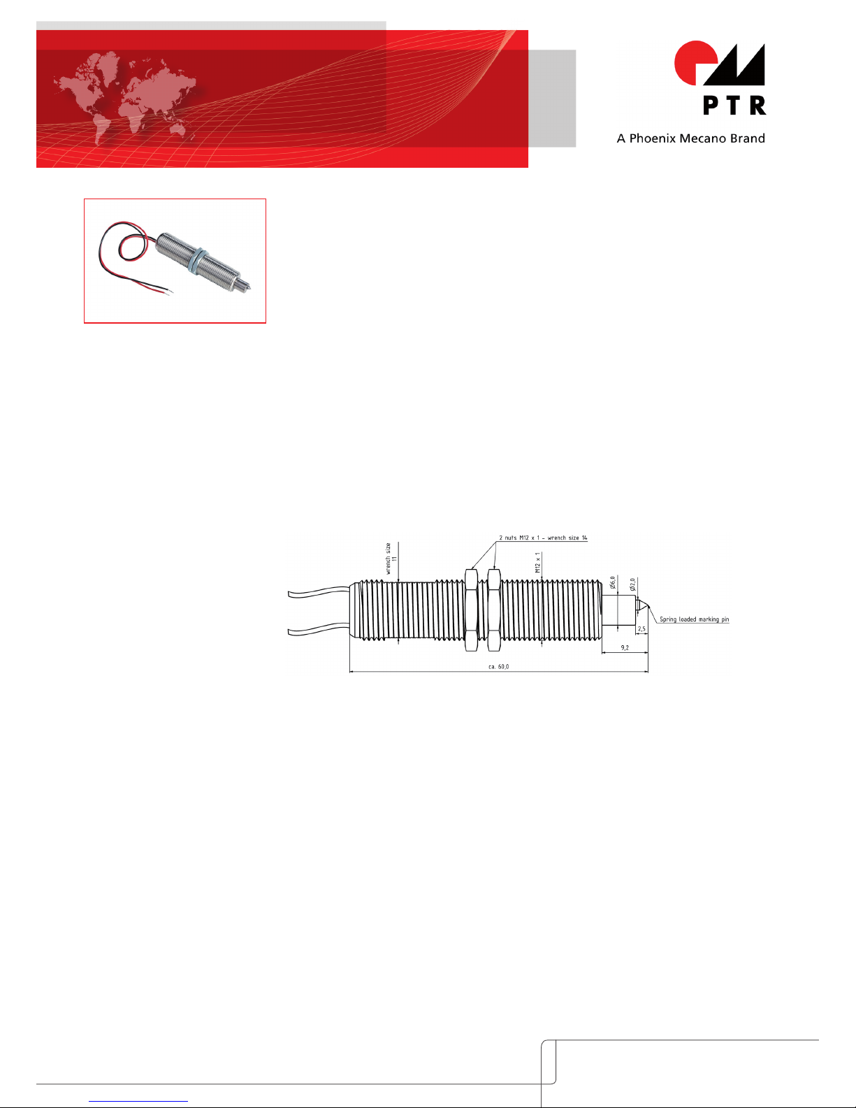
DESIGN / DIMENSION
DESCRIPTION OF FUNCTION
The marker probe is integrated in the test adaptor by means of the outer thread M12x1. During the
test sequence, the spring-loaded marking pin contacts the PCB, and, if the measurement is positive,
the marker probe motor receives a 12 V impulse. This initiates a rotation of the marking pin, which,
as a result of mechanical scoring, marks ∅ 2 mm diameter circle.
CORRECT USE
Thanks to its compact design, PTR Messtechnik‘s PCB marker probe can be incorporated in every ICT
or function test adapter and was specifically designed for this purpose. The outer thread covers the
entire length, so the unit‘s height is easily adjustable and can be matched to any PCB. The sturdy,
exchangeable marking pin guarantees good marking of the PCB.
PTR HARTMANN GmbH • Gewerbehof 38 • 59368 Werne / Germany
Phone: +49 (0)2389/7988-0 • Fax: +49 (0)2389/798888 • E-Mail: info@ptr.eu
Thanks to its compact design, PTR Messtechnik's PCB marker
can be incorporated in every ICT or function test adapter. The
outer thread covers the entire length, so the unit's height is
easily adjustable and can be matched to any PCB. The sturdy,
exchangeable marking pin guarantees good marking of the
PCB.
OPERATING INSTRUCTIONS
SK 790
www.ptr.eu
PTR HARTMANN GmbH • Gewerbehof 38 • 59368 Werne / Germany
Phone: +49 (0)2389/7988-0 • Fax: +49 (0)2389/798888 • E-Mail: info@ptr.eu
AVOIDING INCORRECT USE
To ensure correct use, the following actions are not permitted:
Any other than the permitted voltages and currents
Marking on surfaces which are live
Marking on transfers between materials (edge of PCB; between PCB and PCB tracks
Never exceed the max. working travel of 2 mm; this is to prevent damage to the gear motor
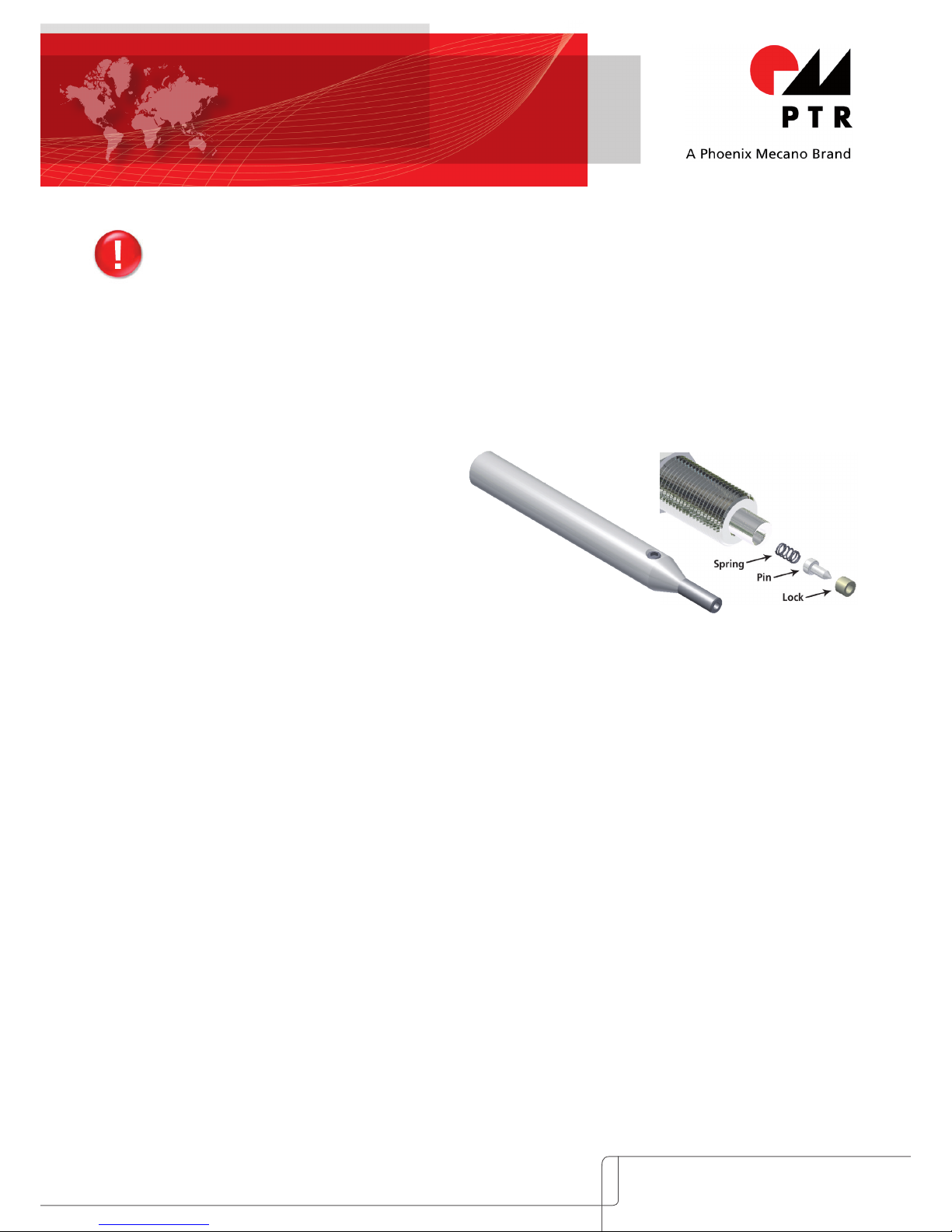
REPLACING THE MARKING PROBE
The replacement kit, which consists of a spring,
pin and lock, can be exchanged in the event of
wear (order no. SK 790-AWE).
To dismantle, remove the pin with pliers. Fit the
new parts in the replacement kit according to
the sketch. The lock has to be plugged onto the
needle with the beveled side. For this purpose we
can supply an insertion tool
(order no. WHE 1200/790) which presses the lock
into the gear shaft drill hole.
OPERATING INSTRUCTIONS
SK 790
TECHNICAL DATA GEAR MOTOR
Output 0.75 W
No-load current 3.7 mA
Starting current 106 mA
Max. permanent load current 81 mA
Terminal resistance 114 Ω
Pin no-load speed 180 min
-1
Max. pin torque 54 mNm
ADDITIONAL SPECIFICATIONS
Pin material Solid carbide
Outer thread M 12x1 with
wrench sizes SW 11
Nuts SW 14
MECHANICAL DATA
Recommended working travel 1.5 mm
Max. working travel 2.0 mm
To prevent damage to
the gear motor, do not
exceed these values.
Spring force for working travel 3.1 N
Marked area ∅ 2.0 mm
Recommended marking impulse ca. 1 s
WHE 1200/790
CE DECLARATION OF INCORPORATION
The manufacturer, PTR Messtechnik GmbH, affirms that as an incomplete
machine, product SK790 (marker probe) complies with the conditions of
Machinery Directive 2006/42/EC. Note that the incomplete machine is not put into operation until the complete machine complies with the directive.
Content-related standards used:
- EN 349:2008-09 Waldemar Lieder
- EN 12100-1:2011-03 Documentation Manager
 Loading...