

Page 1
User Manual
TPUH408TU-UK
3x1 Wallplate Transmitter Switcher with HDMI
and USB-C
All Rights Reserved
Version: TPUH408TU-UK_2018V1.1
Page 2

3x1 Wallplate Transmitter Switcher with HDMI and USB-C
Preface
Read this user manual carefully before using the product. Pictures shown in this
manual are for reference only. Different models and specifications are subject to real
product.
This manual is only for operation instruction, please contact the local distributor for
maintenance assistance. The functions described in this version were updated till
September, 2018. In the constant effort to improve the product, we reserve the right to
make functions or parameters changes without notice or obligation. Please refer to the
dealers for the latest details.
FCC Statement
This equipment generates, uses and can radiate radio frequency energy and, if not
installed and used in accordance with the instructions, may cause harmful interference
to radio communications. It has been tested and found to comply with the limits for a
Class A digital device, pursuant to part 15 of the FCC Rules. These limits are designed
to provide reasonable protection against harmful interference in a commercial
installation.
Operation of this equipment in a residential area is likely to cause interference, in which
case the user at their own expense will be required to take whatever measures may be
necessary to correct the interference.
Any changes or modifications not expressly approved by the manufacture would void
the user’s authority to operate the equipment.
Page 3

3x1 Wallplate Transmitter Switcher with HDMI and USB-C
SAFETY PRECAUTIONS
To ensure the best performance from the product, please read all instructions carefully
before using the device. Save this manual for further reference.
Unpack the equipment carefully and save the original box and packing material for
possible future shipment.
Follow basic safety precautions to reduce the risk of fire, electrical shock and injury
to persons.
Do not dismantle the housing or modify the module. It may result in electrical shock
or burn.
Using supplies or parts not meeting the products’ specifications may cause
damage, deterioration or malfunction.
Refer all servicing to qualified service personnel.
To prevent fire or shock hazard, do not expose the unit to rain, moisture or install
this product near water.
Do not put any heavy items on the extension cable in case of extrusion.
Do not remove the housing of the device as opening or removing housing may
expose you to dangerous voltage or other hazards.
Install the device in a place with fine ventilation to avoid damage caused by
overheat.
Keep the module away from liquids.
Spillage into the housing may result in fire, electrical shock, or equipment damage.
If an object or liquid falls or spills on to the housing, unplug the module immediately.
Do not twist or pull by force ends of the optical cable. It can cause malfunction.
Do not use liquid or aerosol cleaners to clean this unit. Always unplug the power to
the device before cleaning.
Unplug the power cord when left unused for a long period of time.
Information on disposal for scrapped devices: do not burn or mix with general
household waste, please treat them as normal electrical wastes.
Page 4

3x1 Wallplate Transmitter Switcher with HDMI and USB-C
Table of Content
1. Product Introduction .................................................................................................... 1
1.1 Features ............................................................................................................ 1
1.2 Package List ...................................................................................................... 2
2. Specification ............................................................................................................... 3
3. Panel Description ........................................................................................................ 4
3.1 Front Panel ........................................................................................................ 4
3.2 Rear Panel ......................................................................................................... 5
3.3 Side Panel ......................................................................................................... 6
4. System Connection ..................................................................................................... 7
5. Button Control ............................................................................................................. 8
5.1 Source Switching ............................................................................................... 8
5.2 Display Control .................................................................................................. 8
6. RS232 Control ............................................................................................................ 9
6.1 RS232 Connection ............................................................................................ 9
6.2 RS232 Control Software ................................ ................................ .................. 10
6.3 RS232 Command ............................................................................................ 11
6.3.1 Device Control ....................................................................................... 11
6.3.2 Source Switching ................................................................................... 11
6.3.3 EDID Management ................................................................................ 11
6.3.4 CEC Control .......................................................................................... 13
7. Button User-defined .................................................................................................. 14
8. Panel Drawing .......................................................................................................... 16
9. Troubleshooting & Maintenance ............................................................................... 17
10. Customer Service ................................................................................................... 18
Page 5

3x1 Wallplate Transmitter Switcher with HDMI and USB-C
1. Product Introduction
Thanks for choosing the TPUH408TU-UK 3x1 Wallplate Transmitter Switcher, which is
designed to switch and extend HDMI or Slimport input signal to far-end display device,
and the transmission distance is up to 131ft/40m at 4K and 229ft/70m at 1080P video
by using a single CATx cable.
The switcher features two HDMI and one Type-C USB inputs, it can be selected by the
SOURCE AUTO button on the front panel. The switcher supports CEC. The DISPLAY
ON/OFF button on front panel is used to control the far-end display device, and it can
be programmed by IR learning or RS232 command to ensure the compatibility with
various display devices. Moreover, 12V-48V PoC allows the switcher can be powered
from the compatible HDBaseT receiver.
1.1 Features
Supports HDMI signal up to 4K@60Hz 4:2:0, Slimport signal up to 4K@30Hz
4:4:4.
Supports HDMI 1.4 standard and HDCP 2.2 compliant. Ensures display of
content-protected media and interoperability with other HDCP compliant devices.
Active input automatic detective.
Extending HDMI signal 4K@60Hz up to 131ft/40m and 1080P@60Hz up to
229ft/70m.
Supports RS232 pass-through with HDBaseT connection and local control.
Supports IR pass-through to extend IR signal to control display device.
The DISPLAY ON/OFF button can be programmed by IR learning feature or
RS232 command.
The HDBT port supports 12V-48V PoC input, the switcher can be powered from
the compatible HDBaseT receiver by the CATx cable, and it also supports 12V24V PoC output.
Firmware upgrade by Micro-USB port.
1
Page 6

3x1 Wallplate Transmitter Switcher with HDMI and USB-C
1.2 Package List
1x TPUH408TU-UK
1x 2-pin Terminal Block
2x 3-pin Terminal Blocks
1x Power Adapter (24V 1.25A)
1x User Manual
Note: Please contact your distributor immediately if any damage or defect in the
components is found.
2
Page 7

3x1 Wallplate Transmitter Switcher with HDMI and USB-C
Input
Input
(2) HDMI, (1) USB-C (Slimport)
Input Connector
(2) Female type A HDMI, (1) Type-C USB,
HDMI Input Resolution
Up to 4K/UHD@60Hz 4:2:0
Slimport Input Resolution
Up to 4K/UHD@30Hz 4:4:4
Output
Output
(1) HDBT OUT
Output Connector
(1) RJ45
HDBT Output Resolution
Up to 4K/UHD@60Hz 4:2:0
Control
Control Ports
(1) IR, (1) FIRMWARE, (1) RS232, (1) IR IN
Control Connector
(1) Built-in IR sensor, (1) Micro-USB,
(2) 3-pin terminal block
General
Bandwidth
10.2Gbps
Transmission Mode
HDBaseT
HDMI Version
1.4
HDCP Version
2.2
Transmission Distance
4K@60Hz≤40M, 1080P@60Hz≤70M
External Power Supply
Input:100V~240V AC; Output: 24VDC 1.25A
Power Consumption
5W max. (408TU only – add extra for HDBaseT
receiver)
Operation Temperature
-10 ~ +40℃
Storage Temperature
-15 ~ +55℃
Relative Humidity
10% ~ 90%
Dimension (W*H*D)
146mm x 86mm x 39mm
Net Weight
230g
2. Specification
3
Page 8

3x1 Wallplate Transmitter Switcher with HDMI and USB-C
1
2
3
4
7
8
5
6
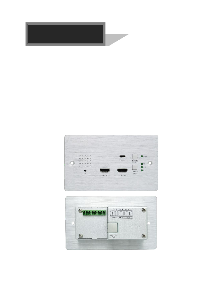
3. Panel Description
3.1 Front Panel
① IR: Built-in IR sensor for IR learning feature. It doesn’t support IR pass-through.
② HDMI IN 1: Type-A HDMI port to connect HDMI source.
③ HDMI IN 2: Type-A HDMI port to connect HDMI source.
④ USB-C: Type-C USB to connect the Macbook or other device with SlimPort output.
⑤ SOURCE AUTO:
Press the backlit button to select the next input source.
Press and hold the button at least 3 seconds to enable auto switching mode.
For more details, please refer to the 5.1 Source Switching on the page 8.
⑥ Input LED:
U: The LED illuminates green to indicate the USB-C input is selected.
H 1: The LED illuminates green to indicate the HDMI 1 input is selected.
H 2: The LED illuminates green to indicate the HDMI 2 input is selected.
⑦ DISPLAY ON/OFF: Turn the display ON or OFF via CEC or RS232 (Programming
required). For more details, please refer to the 5.2 Display Control on the page 8.
⑧ LINK LED: The LED illuminates green to indicate a successful data link with the
HDBaseT receiver.
4
Page 9

3x1 Wallplate Transmitter Switcher with HDMI and USB-C
1
2
3
4
3.2 Rear Panel
① HDBT (POC): RJ45 HDBaseT output port to connect to the HDBT IN port of the
receiver by a CATx cable. It supports 12V-48V PoC to enable the switcher can be
powered from a compatible receiver.
② RS232: Either 3-pin terminal block to connect a control device (such as PC) to
send the RS232 command to control this unit, or to connect a third party device
which needs to be controlled by RS232 pass-through. For more details, please
refer to the 6. RS232 Control on the page 9.
③ DC IN: Power port to connect 24V DC power adapter.
④ IR IN: 3-pin terminal block to connect an IR receiver.
5
Page 10

3x1 Wallplate Transmitter Switcher with HDMI and USB-C
FIRMWARE
1
3.3 Side Panel
① FIRMWARE: Micro-USB port for firmware upgrade.
6
Page 11

3x1 Wallplate Transmitter Switcher with HDMI and USB-C
MacB ook
PoC
HDBT OUT
RS232
Tx Rx
DC IN IR IN
Sig 5V24V
RXTX
Projector
Lapt op Blu- ray
Projector Screen
Power In
HDMI :
HDBa seT:
USB:
Powe r:
RS23 2:
PoC
4. System Connection
Usage Precautions
Make sure all components and accessories included before installation.
System should be installed in a clean environment with proper temperature and
humidity.
All of the power switches, plugs, sockets, and power cords should be insulated and
safe.
All devices should be connected before power on.
The following diagram illustrates typical input and output connection that can be utilized
with the switcher:
Note: We recommend CATx cabling with alien crosstalk prevention technology to
ensure the performance of HDBaseT link.
7
Page 12

3x1 Wallplate Transmitter Switcher with HDMI and USB-C
5. Button Control
5.1 Source Switching
1) Press the SOURCE AUTO button to switch to next source device, and then the
corresponding input LED will turn green.
2) Press and hold the SOURCE AUTO button at least 3 seconds to enable auto
switching mode, and it abides by the following principles:
New Input
Once detecting a new input signal, the switcher will automatically switch to this new
signal, and the far-end display device will receive command to be switched on. If
source input is not detected, the far-end display device will automatically turn off
within two minutes.
Source Removed
When an active source is removed, the switcher will switch to the first available
active input starting at HDMI IN 1.
Reboot
The switcher can save the last configuration before losing power. If the last
switching mode is auto switching, the switcher will automatically enter auto
switching mode once rebooted, then detect all inputs and memorize their
connection status for future rebooting using. If the last selected input source is still
available, the switcher will switch to this input. If not, it will switch to the first
available active input source starting at HDMI IN 1.
Exit auto switching mode
Press and hold the SOURCE (AUTO) button for 3 seconds again to exit the auto
mode, and the input source will not be changed.
5.2 Display Control
1) Press the DISPLAY ON/OFF button to turn on/off the display.
2) If the incompatible display device needs to be used with this switcher, the DISPLAY
ON/OFF button can be programed by IR learning or RS232 command. For more
details, please refer to the 7 Button User-defined on the page 14.
8
Page 13

3x1 Wallplate Transmitter Switcher with HDMI and USB-C
Laptop
RXTX
Projector
Power In
PoC
Laptop
6. RS232 Control
6.1 RS232 Connection
According the RS232 control mode, there are two types of RS232 connection can be
selected.
① When only control the local switcher, connect a control device (e.g. PC) to the
RS232 port of the switcher, the connection diagram shown as below:
② When control the far-end third party device from local control device (e.g. PC),
connect the PC to the RS232 port of the switcher, and then connect the third party
device (e.g. projector) to the RS232 port of receiver. The connection diagram shown
as below:
9
Page 14

3x1 Wallplate Transmitter Switcher with HDMI and USB-C
Parameter configuration area
Monitoring area, show the commands
and its feedback information.
Command sending area
6.2 RS232 Control Software
Installation: Copy the control software file to the control PC.
Uninstallation: Delete all the control software files in corresponding file path.
Basic Settings:
Connect TPUH408TU-UK with all input devices and output devices needed, then to
connect it with a computer which is installed with RS232 control software. Double-click
the software icon to run this software.
Here take the software CommWatch.exe as example. The icon is showed as below:
The interface of the control software is showed as below:
Please set the parameters of COM number, bound rate, data bit, stop bit and the parity
bit correctly, and then you are able to send command in command sending area.
10
Page 15

3x1 Wallplate Transmitter Switcher with HDMI and USB-C
Command
Function
Feedback Example
50617%
Restore factory default
FACTORY RESET
50699%
Get firmware version
VERSION Vx.x.x
50740%
Disable DISPLAY ON/OFF button.
DISABLE DISPLAY ON/OFF
KEY
50741%
Enable DISPLAY ON/OFF button.
ENABLE DISPLEY ON/OFF
KEY
Command
Function
Feedback Example
50701%
Switch to HDMI 1.
SWITCH TO HDMI1
50702%
Switch to HDMI 2.
SWITCH TO HDMI2
50704%
Switch to USB-C.
SWITCH TO USB-C
50710%
Enable auto switching mode.
AUTO SWITCHING
50711%
Enable manual switching mode.
MANUAL SWITCHING
50712%
Get the Source Switching mode.
AUTO SWITCHING
MANUAL SWITCHING
Command
EDID
Feedback Example
50768%
720P PCM 2CH
EDID:720P, PCM 2CH
50769%
720P Dolby/DTS PCM 6CH
EDID:720P, DOLBY/DTS
PCM 6CH
50770%
1080P PCM 2CH
EDID:1080P,PCM 2CH
50771%
1080P Dolby/DTS PCM 6CH
EDID:1080P, DOLBY/DTS
6CH
50772%
4K@30Hz PCM 2CH
EDID:4K30, PCM 2CH
50773%
4K@30Hz Dolby/DTS 5.1
EDID:4K30, DOLBY/DTS 5.1
50774%
1280x720@60Hz DVI
EDID:1280x720@60, DVI
6.3 RS232 Command
Communication protocol: RS232 Communication Protocol
Baud rate: 9600 Data bit: 8 Stop bit: 1 Parity bit: none
6.3.1 Device Control
6.3.2 Source Switching
6.3.3 EDID Management
The input resolution (EDID setting) can be set using RS232 commands to one of the
options given in the following table.
11
Page 16

3x1 Wallplate Transmitter Switcher with HDMI and USB-C
50775%
1920x1080@60Hz DVI
EDID:1920x1080@60, DVI
50776%
1920x1200 PCM 2CH 6CH
EDID:1920x1200, PCM 2CH
6CH
50777%
3840x2160@60Hz 4:2:0 8 bit
EDID:3840x2160@60, 4:2:0
8BIT
50782%
Enable EDID user-defined mode.
Uploading the user-defined EDID file
by Micro-USB port within 10 seconds.
EDID: USER
50783%
EDID bypass
EDID: BYPASS
50784%
Get the current EDID.
EDID:720P, PCM 2CH
EDID:720P, DOLBY/DTS
PCM 6CH
EDID:1080P,PCM 2CH
EDID:1080P, DOLBY/DTS
6CH
EDID:4K30, PCM 2CH
EDID:4K30, DOLBY/DTS 5.1
EDID:1280x720@60, DVI
EDID:1920x1080@60, DVI
EDID:1920x1200, PCM 2CH
6CH
EDID:3840x2160@60, 4:2:0
8BIT
EDID: USER
EDID: BYPASS
12
Page 17

3x1 Wallplate Transmitter Switcher with HDMI and USB-C
Command
Function
Feedback Example
50730%
Volume up.
CEC VOLUME INCREASE
50731%
Volume down.
CEC VOLUME DECREASE
50732%
Volume mute toggle.
CEC VOLUME MUTE
50733%
Display on.
CEC DISPLAY ON
50734%
Display off.
CEC DISPLAY OFF
CEC
<xx:xx:xx....>
Send CEC command “xx:xx:xx…” to
control display device.
CEC <xx:xx:xx…>
6.3.4 CEC Control
The switcher also supports sending of a few common CEC commands using RS232
command code. Specific CEC command can also be sent from the switcher. The
RS232 commands are as given in the following table. Please note that only CEC
enabled devices that have the specified logical address will respond to CEC
commands.
13
Page 18

3x1 Wallplate Transmitter Switcher with HDMI and USB-C
7. Button User-defined
Press the DISPLAY ON/OFF button can turn on/off the display. If the incompatible
display device needs to be used, the DISPLAY ON/OFF button can be programed by
IR learning feature or RS232 command.
IR learning feature:
Please according the below IR learning steps to defined the DISPLAY ON/OFF button.
1) Press and hold both the DISPLAY ON/OFF and SOURCE AUTO button until the
both the button LEDs flash alternately.
2) Use the DISPLAY ON/OFF button to choose the command be set:
Rapid flashing indicates that DISPLAY ON mode is selected.
Slow flashing indicates that DISPLAY OFF mode is selected.
3) Point the IR remote at the IR sensor and press the respective button on the IR
remote.
4) The DISPLAY ON/OFF button LED will stop flashing and remain lit to indicate that
IR command has been learnt.
5) Press and hold the SOURCE AUTO button until the both the button LEDs go out to
exit the IR learning mode. The switcher will enter auto switching mode five
seconds later.
Note: The IR learning function will self-terminate after 30 seconds of inactivity.
14
Page 19

3x1 Wallplate Transmitter Switcher with HDMI and USB-C
Command
Format
Function
Command Example
/+kb: xxxx
k=0, Set the DISPLAY ON
k=1, Set the DISPLAY OFF
xxxx: ASCII characters
b=0, Baud rate is 2400
b=1, Baud rate is 4800
b=2, Baud rate is 9600
b=3, Baud rate is 19200
b=4, Baud rate is 38400
b=5, Baud rate is 57600
b=6, Baud rate is 115200
/+02:abc123
Set the DISPLAY ON to
send the ASCII
characters abc123.
/-kb:xx xx xx
xx
k=0, Set the DISPLAY ON
k=1, Set the DISPLAY OFF
xx xx xx xx: HEX characters
b=0, Baud rate is 2400
b=1, Baud rate is 4800
b=2, Baud rate is 9600
b=3, Baud rate is 19200
b=4, Baud rate is 38400
b=5, Baud rate is 57600
b=6, Baud rate is 115200
/-12:30 31 32 33
Set the DISPLAY OFF to
send the HEX characters
30 31 32 33.
/x0:xxx
Set the booking shutdown time to
xxx.
SET TIME TO xxx
MINUTES
TO TURN OFF THE
DISPLAY IF NO
SOURCE DETECTED
Programed by RS232 command:
The DISPLAY ON/OFF button also can be defined to send control characters by
following the below command format.
15
Page 20

3x1 Wallplate Transmitter Switcher with HDMI and USB-C
FIRMWARE
120.60 mm
146.00 mm
86.00 mm
108
.63 mm
lower level
26.2mm
39.1mm
48.80 mm
3.00 mm
39.10 mm
8. Panel Drawing
16
Page 21

3x1 Wallplate Transmitter Switcher with HDMI and USB-C
Problems
Potential Causes
Solutions
Color losing or no video
signal output in HDMI
display.
The connecting cables
may not be connected
correctly or it may be
broken.
Check whether the cables
are connected correctly
and in working condition.
No HDMI signal output in
the device while local
HDMI input is in normal
working state.
Output image with white
noise.
POWER indicator doesn’t
work or no respond to any
operation.
Loose or failed power
cord connection.
Ensure the power cord
connection is good.
9. Troubleshooting & Maintenance
Note: If your problem still remaining after following the above troubleshooting steps,
please contact your local dealer or distributor for further assistance.
17
Page 22

3x1 Wallplate Transmitter Switcher with HDMI and USB-C
10. Customer Service
The return of a product to our Customer Service implies the full agreement of the terms
and conditions hereinafter. There terms and conditions may be changed without prior
notice.
1) Warranty
The limited warranty period of the product is fixed three years.
2) Scope
These terms and conditions of Customer Service apply to the customer service
provided for the products or any other items sold by authorized distributor only.
3) Warranty Exclusion
Warranty expiration.
Factory applied serial number has been altered or removed from the product.
Damage, deterioration or malfunction caused by:
Normal wear and tear.
Use of supplies or parts not meeting our specifications.
No certificate or invoice as the proof of warranty.
The product model showed on the warranty card does not match with the
model of the product for repairing or had been altered.
Damage caused by force majeure.
Servicing not authorized by distributor.
Any other causes which does not relate to a product defect.
Shipping fees, installation or labor charges for installation or setup of the
product.
4) Documentation:
Customer Service will accept defective product(s) in the scope of warranty
coverage at the sole condition that the defeat has been clearly defined, and upon
reception of the documents or copy of invoice, indicating the date of purchase, the
type of product, the serial number, and the name of distributor.
Remarks: Please contact your local distributor for further assistance or solutions.
18
 Loading...