

PTN MV4 User Manual
DVI Video Processing Switcher 4x4
PTN Electronics Limited www.PTN-electronics.com
MV4
PTN DVI Video Processing Switcher 4x4
USER MANUAL
Version: MV42013V1.4

DVI Video Processing Switcher 4x4
PTN Electronics Limited www.PTN-electronics.com
NOTICE: Please read this user manual carefully before using this product.
Update History
Version
Date
Update Content
1.0
2013.01.08
First version.
1.1
2013.02.19
Modified some introductions about MV4.
1.2
2013.03.07
Modified the diagram of 3x zoom-in displaying and
some parameters.
1.3
2013.03.18
Modified the diagram of multi-viewer displaying, 3x
zoom-in displaying.
1.4
2013.05.20
Modified the diagrams.
This is a manual for video processor MV4.
This manual is for operation instruction only, not for any maintenance usage. The
functions described in this version are updated till May, 2013. Any changes of
functions and parameters since then will be informed separately. Please refer to the
dealers for the latest details.
This manual is copyright PTN Electronics Limited. All rights reserved. No part of
this publication may be copied or reproduced without the prior written consent of
PTN Electronics Limited.
All product function is valid till 2013-05-20.

DVI Video Processing Switcher 4x4
PTN Electronics Limited www.PTN-electronics.com
Table of Contents
1. Introduction ............................................................................................................. 1
1.1. Introduction to MV4 ........................................................................................ 1
1.2. Package Contents.......................................................................................... 1
2. Specification ........................................................................................................... 1
3. Rear Panel and Connection ................................................................................... 2
3.1. Rear panel introduction ................................ .................................................. 2
3.2. Connection with RS232 Communication Port ................................................ 3
3.3. Connection with USB Interface ...................................................................... 4
3.4. Twist Pair Connection .................................................................................... 4
4. Operations of the Front Control Panel .................................................................... 5
4.1. Front Panel Introduction ................................................................................. 5
4.2. Operations of the Menu Buttons .................................................................... 6
4.3. Operations of the Input/output Selection Buttons ........................................... 6
4.4. Operations of the Function Buttons................................................................ 7
4.5. Operations of the Customized Buttons and the Numeric keys ....................... 8
4.6. Menu Levels Introduction ............................................................................... 8
5. Operations of the Software ................................................................................... 11
5.1. Introduction of the Software ......................................................................... 11
5.1.1. Installation & uninstallation .................................................................. 11
5.1.2. Control connection............................................................................... 11
5.2. Main Interface .............................................................................................. 12
5.3. Menu Bar Function Settings ......................................................................... 12
5.3.1. File Button ........................................................................................... 12
5.3.2. Connection Button ............................................................................... 13
5.3.3. View Button ......................................................................................... 13
5.3.4. Help Button .......................................................................................... 13
5.4. Main Function Settings ................................................................................ 13
5.4.1. 4x Zoom-in Function ............................................................................ 14
5.4.2. 3x Zoom-in Function ............................................................................ 14

DVI Video Processing Switcher 4x4
PTN Electronics Limited www.PTN-electronics.com
5.4.3. Matrix Switching Function (Full Displaying) ......................................... 15
5.4.4. Picture in Picture (PIP) Displaying ................................ ....................... 15
5.4.5. Picture outside Picture (POP) Displaying ............................................ 17
5.5. Additional Function Settings ........................................................................ 19
5.5.1. Settings in the Auxiliary Function Area ................................................ 19
5.5.2. Settings in the Function Area on the Main Panel ................................. 23
5.6. Advanced Function Settings ........................................................................ 25
5.6.1. Display Mode Setting........................................................................... 25
5.6.2. Shortcut Button Customization ............................................................ 27
6. System Diagram ................................................................................................... 28
6.1. Diagram of Video Wall Displaying ................................................................ 28
6.2. Diagram of Multi-Viewer Displaying ............................................................. 30
6.3. Diagram of Full Images Displaying .............................................................. 31
7. Firmware Upgrade ................................................................................................ 33
8. Troubleshooting & Maintenance ........................................................................... 34
9. Safety Operation Guide ........................................................................................ 35
10. After-sales Service ............................................................................................... 36
DVI Video Processing Switcher 4x4
PTN Electronics Limited 1 www.PTN-electronics.com
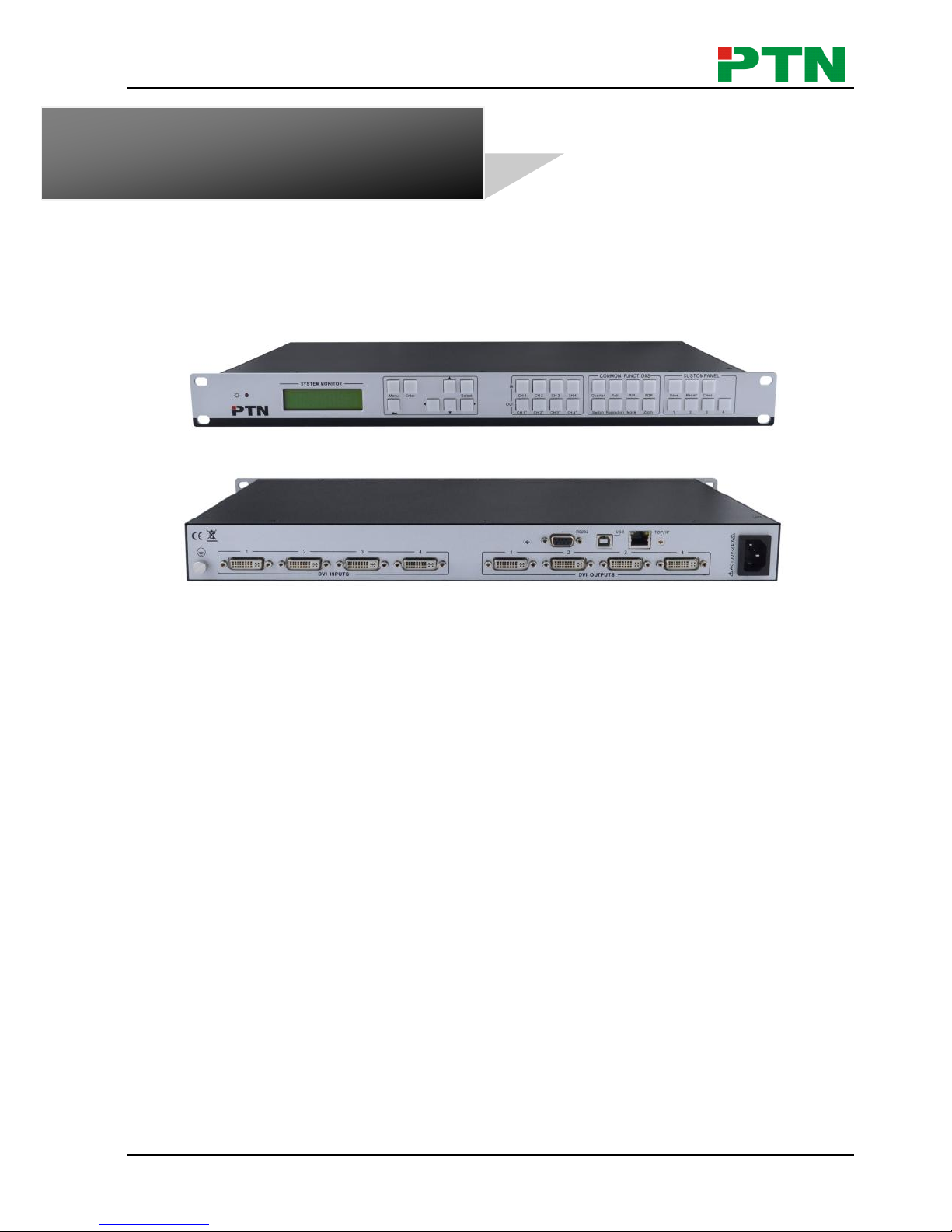
1. Introduction
1.1 Introduction to MV4
MV4 is a powerful, universal and user-friendly image analyzing processor with 4 DVI
input ports and 4 output ports. It is not only a matrix switcher, but also a Multi-viewer or
video wall processor.
As a video wall processor, MV4 is able to zoom in one input image three/ four times to
the outputs. And as a Multi-viewer processor, MV4 can mix inputs with any combos to
one image, and then transfer to all the outputs. It also supports output resolution
change, contrast & brightness adjusting, H&V zooming and moving, and bezel
adjustment.
MV4 provides with various ways for system control through its control ports, such as
the RS232 serial port, USB interface, and the TCP/IP network port. It can be controlled
easily by using the control software MV4Demo.
It has a good application in various occasions, such as TV broadcasting, multi-media
meeting room, network operations center, medical institutions, command & control
center etc.
1.2 Package Contents
1 x MV4
1 x RS232 cable (1.35m in length)
1 x Power Cord
4 x Plastic cushions
1 x User Manual
Notes: Please confirm if the product and the accessories are all included, if not,
please contact with the dealers.
2. Specification
Video Input
Video Output
Input
4 DVI
Output
4 DVI
Input Connector
Female DB 24+5
Output Connector
Female DB 24+5
Input Level
T.M.D.S. 2.9V/3.3V
Output Level
T.M.D.S. 2.9V/3.3V
Input Impedence
50Ω
Output Impedence
50Ω
Video General
Video Signal
DVI (or T.M.D.S)
Switching Speed
200ns (Max.)
DVI Video Processing Switcher 4x4
PTN Electronics Limited 2 www.PTN-electronics.com
Bandwidth
340 MHz
(6.75Gbit/s)
Transport Delay
5nS (±1nS)
Crosstalk
<-50dB@5MHz
Control Parts
Control
Buttons,
RS232 (9-pin
female D connector)
Pin Configurations
2 = TX, 3 = RX, 5 =
GND
Control Software
MV4Demo, trough
USB port.
Options
TCP/IP control by
PTNET
General
Power Supply
100VAC ~ 240VAC,
50/60Hz
Temperature
-20 ~ +70℃
Humidity
10% ~ 90%
Power
Consumption
25W
Case
Dimension
W483 x H44x
D235mm
Product Weight
5.2Kg
3. Rear Panel and Connection
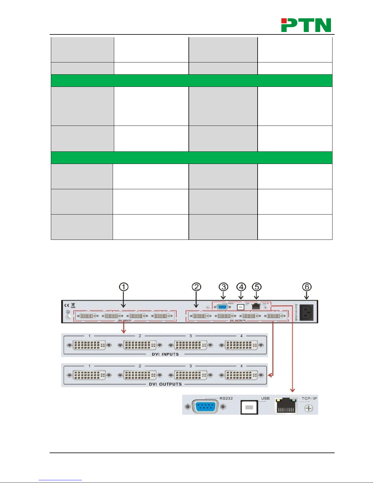
3.1 Rear panel introduction
Figure 3-1 MV4 Interface Introduction
DVI Video Processing Switcher 4x4
PTN Electronics Limited 3 www.PTN-electronics.com
No.
Name
Description
①
DVI INPUTS
DVI-I connector, 4 input ports.
②
DVI OUTPUTS
DVI-I connector, 4 output ports.
③
RS232
9-pin female connector, for serial control.
④
USB
USB interface, type B, for USB control and firmware
update.
⑤
TCP/IP
TCP/IP network port. User can control MV4 with
control software MV4Demo after setting the right IP
address in it.
⑥
AC100V~240V
Used for accessing the household current power.
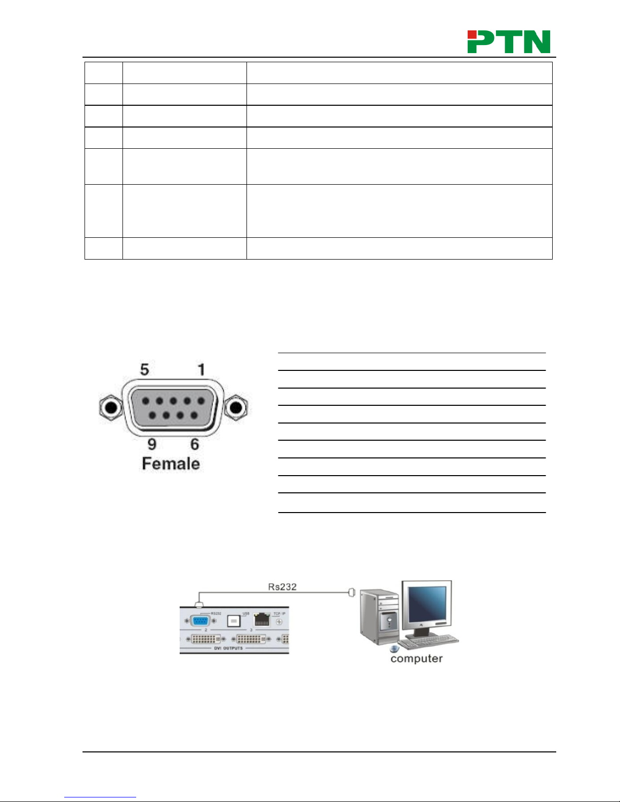
3.2 Connection with RS232 Communication Port
With the RS232 port, the processing switchers can be control by the control
software MV4Demo. This RS232 communication port is a female 9-pin D connector.
The definition of its pins is as the table below.
No. Pin Function
1 N/u Unused
2 Tx Transmit
3 Rx Receive
4 N/u Unused
5 Gnd Ground
6 N/u Unused
7 N/u Unused
8 N/u Unused
9 N/u Unused
Figure 3-2 9HDF
Please connect reference to the following contents.
1) Use a RS232 cable to connect the COM port of the computer to the RS232
connector of MV4.
Figure 3-3 Connect with PC
2) Run the control software and select RS232 connection.
3) If connection is OK, then we can control the MV4.
DVI Video Processing Switcher 4x4
PTN Electronics Limited 4 www.PTN-electronics.com
3.3 Connection with USB Interface
By connecting the USB interface between the switcher and the computer, user can
control MV4 through its USB interface. Before controlling, please install the USB driver
and the control software MV4Demo (as shown in Operations of the Software) in the
controlling computer, and check if it is well connected. Plug and play and hot plug
function are supported by the USB interface of MV4.
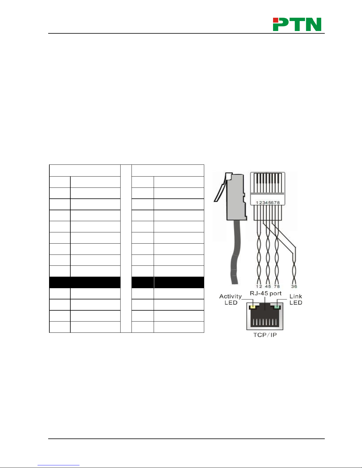
3.4 Twist Pair Connection
MV4 provides with TCP/IP communication port, user can control it by using the related
communication software.
Activity LED: The yellow LED always blinks when the network works normally.
Link LED: The green LED keeps on when the network linked.
RJ-45 port: RJ45 communication port.
Notice: Cable connectors can use T568A or T568B standard, but must be the same
on both sides of one cable.
TIA/EIA T568A
TIA/EIA T568B
Cable color
Pin
Cable color
1
green white
1
orange white
2
green
2
orange
3
orange white
3
green white
4
blue
4
blue
5
blue white
5
blue white
6
orange
6
green
7
brown white
7
brown white
8
brown
8
brown
1st
4--5
1st
4--5
2nd
3--6
2nd
1--2
3rd
1--2
3rd
3--6
4th
7--8
4th
7--8
DVI Video Processing Switcher 4x4
PTN Electronics Limited 5 www.PTN-electronics.com
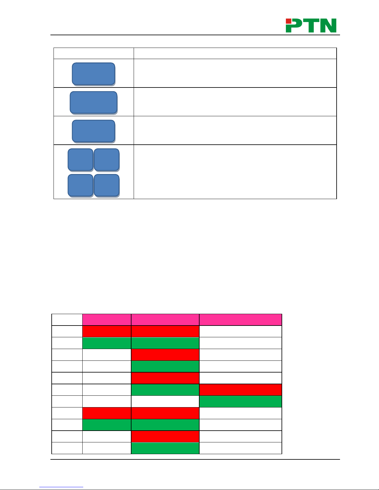
4. Operations of the Front Control Panel
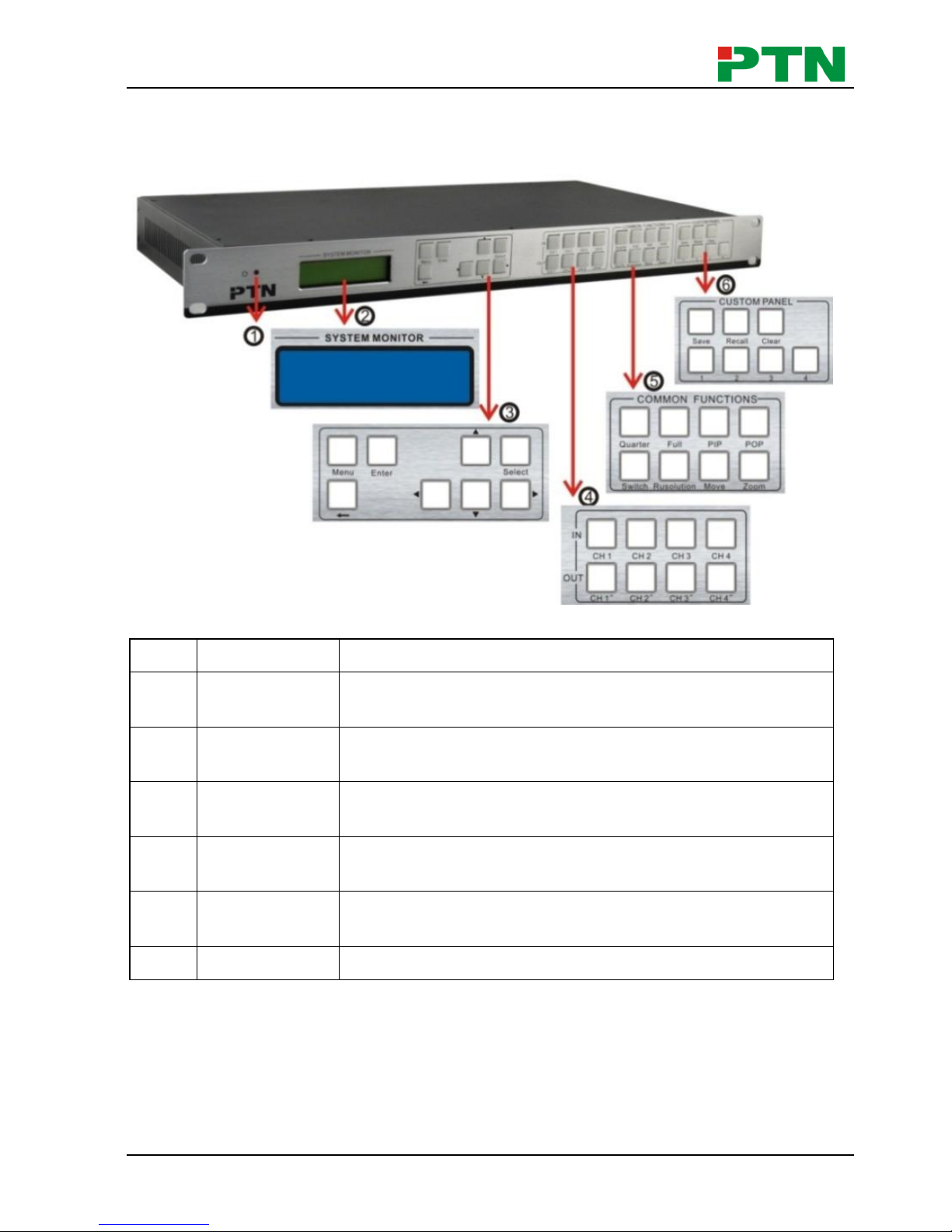
4.1 Front Panel Introduction
Figure 4-1 Front Panel Introduction
No.
Name
Description
①
Power
indicator
Turns on when power on.
②
LCD
System monitor, to indicate the operations and the
real-time running state.
③
Menu function
panel
Choose the functional button required and confirm.
④
Input/output
channels
4 input channels and 4 output channels.
⑤
Function
pattern panel
Common functions for output image displaying effects.
⑥
Custom panel
Used for saving or recovering the customized settings.
Note: Part ④, ⑤ and ⑥ are the operation areas for shortcut.
1) For the non-numeric buttons, you can use the menu buttons after you press on any
numeric buttons, or use the numeric buttons directly.
Example:
Press the button move to enter into the menu of HP/VP settings.
Press the button resolution, it will show the corresponding menu.
DVI Video Processing Switcher 4x4
PTN Electronics Limited 6 www.PTN-electronics.com
Press the numeric button 1 directly, and then the resolution will be set to 1080P
(Without selection confirmation).
2) For the numeric buttons (Including the Input/output Selection Buttons), it will show
the corresponding menu when press on any of them, uses without selection
confirmation.
3) The priority of the buttons of different menu levels is showed in 4.6 Menu Levels
Introduction.
Below are the detailed introductions for every button.
4.2 Operations of the Menu Buttons
Buttons
Operation Description
Switch cyclically between the menu items in the same
level. For example, switch cyclically in the first level of the
menu between Quarter, Full, PIP, POP, Factory set, SAVE,
RECALL and CLEAR.
Return to the previous level of the menu.
Enter to the next level of the menu. For example, to enter to
the second level of the menu Resolution from the first
level of the menu Full.
Execute the operations selected.
To move the on-screen cursor or adjust the position of the
image.
Increase or decrease the value of the parameter, such as
channel, resolution etc.
4.3 Operations of the Input/output Selection Buttons
Buttons
Operation Description
Select the corresponding input
image from the images of the 4
input channels.
Select the corresponding output
image form the images of the 4
output channels.
Note:
CH4′
CH3′
CH2′
CH1′
CH4
CH3
CH2
CH1
∨
∧
>
<
Select
Enter
←
Menu
DVI Video Processing Switcher 4x4
PTN Electronics Limited 7 www.PTN-electronics.com
1) While it is in 4x full screen zoom-in and 3x zoom-in function menu, it is unable to
set the input or the output channels, except to set the resolution of the 4 output
channels as a whole.
2) While it is in POP and PIP menu, it is able to set on a single input channel or a
single output channel.
4.4 Operations of the Function Buttons
Buttons
Operation Description
4x full zoom-in function and 3x zoom-in function, two default
display modes.
Matrix switching displaying or distribution displaying, five
default modes in total. All through mode is the first one.
Picture in picture (PIP) displaying, 3 default modes in total.
Picture outside picture (POP) displaying, 5 default modes in
total.
Select the input channels or the output channels, it is
available together with the input channel buttons or the
output channel buttons when use.
Set the output resolution, supports 1080P, 720P, WUXGA,
UXGA, SXGA, and XGA.
Adjust the position of the image, it is available together with
the direction buttons (up, down, left and right) when use.
Set the focus of the image to scale the image, it is available
together with the direction buttons (up, down, left and right)
when use.
zoom
move
resolution
switch
POP
PIP
full
Quarter
DVI Video Processing Switcher 4x4
PTN Electronics Limited 8 www.PTN-electronics.com
4.5 Operations of the Customized Buttons and the Numeric keys
Buttons
Operation Description
Customize shortcut buttons of different menu levels and
save the settings.
Customized menu button call.
Shortcut button, to clear the customized menu.
Numeric buttons, to set the corresponding shortcut buttons
of different menu levels.
Note: In the operational area of the shortcut buttons, when you press on any button, it
will show the detailed information of the present menu on the LCD screen.
4.6 Menu Levels Introduction
In this part, we mainly introduce the priority of the menu when operate.
First Level includes: Quarter, full, PIP, POP, Factory set, SAVE, RECALL, and CLEAR.
Second Level includes: resolution, set position, adjust windows, overlay, board, display,
and channel Switch.
Third Level includes: brightness, contrast and CH’.
The relationship of each level of the menu is showed as below.
First Level
Second Level
Third Level
MENU
Quarter
Type 1
MENU
rusolution
1 1920X1080
MENU
Colour
MENU
OUT 1
brightness 0512
contrast 100
MENU
FULL
Channel Switch
Type 1
IN 1 OUT 1
MENU
rusolution
1 1920X1080
4 3 2
1
CLEAR
RECALL
SAVE
 Loading...