

PTN MTX Series, MTX200, MTX400, MTX500 User Manual

PTN Electronics
r
MTX Series Matrix Switcher
User Manual
Please read this manual carefully before using this product.
MTXSeries ---Combo Matrix Switche

Notice:
This MTX series Matrix Switchers User Manual takes example of the Matrix
model MTX400. It can be used as user’s manual of other MTX series matrix
switcher models.
This manual is only an instruction for operators, not for any maintenance usage.
The functions described in this version are updated till Jan 2010. Any changes of
functions and parameters since then will be informed separately. Please refer to
the dealers for the latest details.
This manual is copyright PTN Electronics Limited. All rights reserved. No part of
this publication may be copied or reproduced without the prior written consent of
PTN Electronics Limited.
All product function is valid till 2010-1-1
MTX Series Matrix Switcher
!
In order to ensure the credibility use of the product and the user’s safety, please comply
with the following items during installation and maintenance:
The system must be earthed properly. Please do not use two blades plugs and ensure the
alternating power supply ranged from 100v to 240v and from 50Hz to 60Hz.
Do not put the switcher in a place of too hot or too cold.
To avoid any damage by over heat, please keep the working environment good in ventilation
to radiate the heat when running the switcher.
The switchers should be turned off when in rainy and humid days or nonuse for a long time,
The alternating power supply line should be disconnected with the power socket during the
following operation.
A. Take out or reinstall any component of the switcher
B. Disconnect or re-connect any connector of the switcher
Please do not attempt to maintain and uncover the switcher for there is a high-voltage
component inside and the risk of the electric shock.
Do not splash any chemical product or liquid on or near the equipment.
Safety Operation Guide
ii
PTN Electronics Limited www.PTN-electronics.com

MTX Series Matrix Switcher
Contents
1. INTRODUCTION ........................................................................................................... 1
1.1 About MTX Matrix Switcher System ...................................................................... 1
1.2 MTX Series Matrix Switcher Models ...................................................................... 1
1.2.1 the MTX series chassis (main unit) . ................................................................... 1
1.2.2 MTX card (changeable cards) ............................................................................. 2
2. PACKING OF THE PRODUCT ...................................................................................... 2
3. INSTALLATION .............................................................................................................. 3
4. FRONT VIEW AND REAR VIEW OF THE PRODUCT .................................................. 3
4.1 Front View of the MTX200 ...................................................................................... 3
4.2 Rear View of the MTX200 ...................................................................................... 4
4.3 Front View of the MTX400 ...................................................................................... 4
4.4 Rear View of the MTX400 ...................................................................................... 5
4.5 Front View of the MTX500 ........................................................................................ 5
4.6 Rear View of the MTX500 ......................................................................................... 6
5. CHANGEABLE CARDS INTRODUCTION AND INST ALLATION .................................. 6
5.1 Introduction of the changeable cards and slots .................................................. 6
5.1.1 MXDV4 ............................................................................................................... 6
5.1.2 MXDV8 ............................................................................................................... 7
5.1.3 MXHD4 ............................................................................................................... 7
5.1.4 MXVG4 ............................................................................................................... 8
5.1.5 MXVG8 ............................................................................................................... 9
5.1.6 MXCV8 ............................................................................................................... 9
5.1.7 MXSV8 ............................................................................................................... 9
5.1.8 MXAU8 ............................................................................................................... 9
5.1.9 MXUS8 ............................................................................................................. 10
5.1.10 MXPA8 ............................................................................................................ 10
5.1.11 MXTP8 ............................................................................................................ 11
5.2 ID setting during installation ............................................................................... 11
5.2.1 Defaulted ID of each slot .................................................................................. 11
5.2.2 ID matching, between the slot and card ............................................................ 12
5.3 Connection of RS-232 Communication Port ...................................................... 13
5.3.1 Connection with Control Systems ..................................................................... 13
5.3.2 Connection with Computer ................................................................................ 13
5.4 Connection of TCP/IP Communication Port (Optional Function) ................... 13
5.5 System Diagram ................................................................................................. 14
6. OPERATION OF THE CONTROL P ANEL ................................................................... 14
iii
PTN Electronics Limited www.PTN-electronics.com

MTX Series Matrix Switcher
6.1 Front Panel Description ....................................................................................... 14
6.2 Command Format of the Switching Operation ................................................... 15
6.3 Examples of Operation ..................................................................................... 16
7. COMMUNICATION PROTOCOL AND COMMAND CODES ....................................... 16
8. SPECIFICATION .......................................................................................................... 19
8.1 Main Unit (Chassis) ............................................................................................... 19
8.2 Changeable Cards ................................................................................................ 20
8.2.1 MXDV4, MXDV8,MXHD4 ................................................................................. 20
8.2.2 MXVG4,MXVG8 ................................................................................................ 20
8.2.3 MXCV8,MXSV8 ................................................................................................ 21
8.2.4 MXAU8 ............................................................................................................. 21
8.2.5 MXPA8 .............................................................................................................. 21
8.2.6 MXUS8 ............................................................................................................. 22
8.2.7 MXTP8 .............................................................................................................. 22
9. TROUBLESHOOTING & MAINTENANCE ................................................................... 23
iv
PTN Electronics Limited www.PTN-electronics.com

MTX Series Matrix Switcher
1. Introduction
1.1 About MTX Matrix Switcher System
MTX series Matrix switcher is a flexible solution for the combo signal management. It is working with
the MX series changeable cards, including various signals, such as VGA, DVG, HDMI, composite video,
s-video, USB2.0, audio mixer, twisted pair etc. It combines all the functions of different cards, to be a
comprehensive audiovisual solution.
Various changeable cards make the MTX series become flexible, and all-in-one solution for different
project. The user can choose the right card, the right function for different application. It includes almost
all the regular audiovisual signals, and control signal. And, PTN electronics limited will launch more and
more new cards, which will work compatible with the MTX series.
Every card works independently, controlled by the main board in the front panel. The cards are
controlled by the RS232, front panel buttons, and TCP/IP (optional function).
Every card is going with the ID identification. So, it works with the main board by internal protocol.
The MTX series product is used for different project, because of the change-able card design. It is the
combo solution for multimedia classroom, control rooms, conference rooms, lecture rooms, shopping
center etc. It will handle all the audiovisual management, including the switching, driving, scaling etc.
F 1-1 MTX400
1.2 MTX Series Matrix Switcher Models
1.2.1 the MTX series chassis (main unit) .
Itcan be classified into the following models:
Specifications
Models
MTX200 2U 3 Signal √ Optional
MTX400 4U 6 Redundant √ Optional
MTX500 5U 8 Redundant √ Optional
PTN Electronics Limited www.PTN-electronics.com
Height Maximum Slot
1
Power
supplies
RS232 control
Network
control
MTX Series Matrix Switcher
1.2.2 MTX card (changeable cards)
According to different situation and users, the MTX card (changeable cards) can be classified into the
following models:
Specifications
Models
MXDV4 4 4 DVI (HDMI) Signal Gang Router
MXDV8 8 8 DVI (HDMI) Double Gang Router
MXHD4 4 4 HDMI (DVI) Signal Gang Router
MXVG4 4 4 VGA Signal Gang Router
MXVG8 8 8 VGA Double Gang Router
MXCV8 8 8 C Video DVI (HDMI) Router
MXSV8 8 8 S Video DVI (HDMI) Router
MXAU8 8 8 Stereo Audio DVI (HDMI) Router
MXUS8 8 8 USB2.0 DVI (HDMI) Router
MXPA8 8 8 Stereo Audio DVI (HDMI) Processor
MXTP8 8 8
All modules above are for separated case design,
Inputs Outputs Signal Format Height Features
VGA T w isted Pair
Double Gang Driver
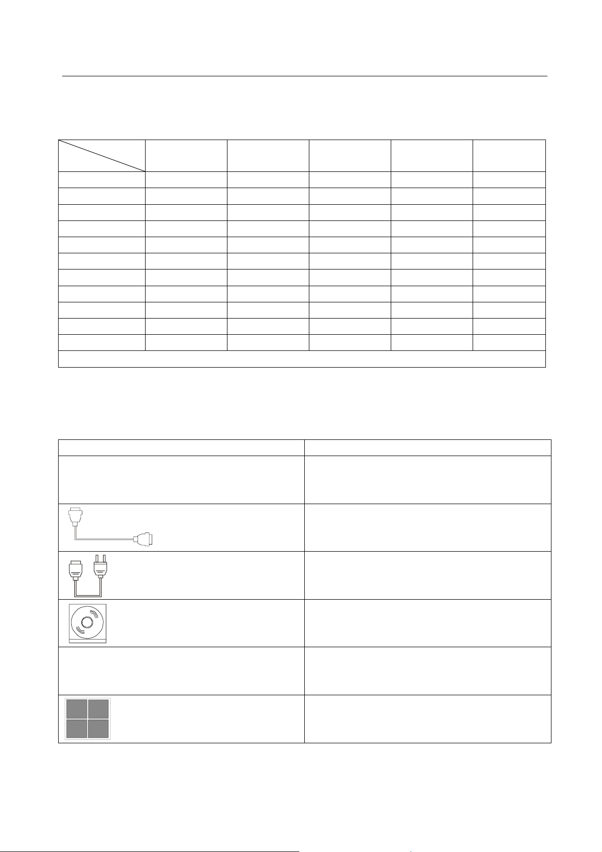
2. Packing of the Product
Pictures Description
MTX matrix switcher (with empty slot and empty
cover)
RS-232 Communication Cord
Power Supply Cord
CD with Application SWITCHER 2.0
User manual
Rubber cushion
2
PTN Electronics Limited www.PTN-electronics.com

MTX Series Matrix Switcher
3. Installation
MTX series matrix switchers adopt metal shell and can be stacked with other device. Moreover, they
are rack-mountable enclosure and can be installed in the standard 19 inches case.
4. Front View and Rear View of the Product
4.1 Front View of the MTX200
3
PTN Electronics Limited www.PTN-electronics.com

MTX Series Matrix Switcher
4.2 Rear View of the MTX200
4.3 Front View of the MTX400
(Crystal Buttons Version)
There are two different button in the front panel.
1: Regular buttons.
Black plastic buttons, with red LED indicating.
2: Crystal buttons.
Crystal buttons, with green back-light indicating, which can insert customized label.
4
PTN Electronics Limited www.PTN-electronics.com
 Loading...