

Page 1

PTN Electronics
r
MTX Series Matrix Switcher
User Manual
Please read this manual carefully before using this product.
MTXSeries ---Combo Matrix Switche
Page 2

Notice:
This MTX series Matrix Switchers User Manual takes example of the Matrix
model MTX400. It can be used as user’s manual of other MTX series matrix
switcher models.
This manual is only an instruction for operators, not for any maintenance usage.
The functions described in this version are updated till Jan 2010. Any changes of
functions and parameters since then will be informed separately. Please refer to
the dealers for the latest details.
This manual is copyright PTN Electronics Limited. All rights reserved. No part of
this publication may be copied or reproduced without the prior written consent of
PTN Electronics Limited.
All product function is valid till 2010-1-1
Page 3
MTX Series Matrix Switcher
!
In order to ensure the credibility use of the product and the user’s safety, please comply
with the following items during installation and maintenance:
The system must be earthed properly. Please do not use two blades plugs and ensure the
alternating power supply ranged from 100v to 240v and from 50Hz to 60Hz.
Do not put the switcher in a place of too hot or too cold.
To avoid any damage by over heat, please keep the working environment good in ventilation
to radiate the heat when running the switcher.
The switchers should be turned off when in rainy and humid days or nonuse for a long time,
The alternating power supply line should be disconnected with the power socket during the
following operation.
A. Take out or reinstall any component of the switcher
B. Disconnect or re-connect any connector of the switcher
Please do not attempt to maintain and uncover the switcher for there is a high-voltage
component inside and the risk of the electric shock.
Do not splash any chemical product or liquid on or near the equipment.
Safety Operation Guide
ii
PTN Electronics Limited www.PTN-electronics.com
Page 4

MTX Series Matrix Switcher
Contents
1. INTRODUCTION ........................................................................................................... 1
1.1 About MTX Matrix Switcher System ...................................................................... 1
1.2 MTX Series Matrix Switcher Models ...................................................................... 1
1.2.1 the MTX series chassis (main unit) . ................................................................... 1
1.2.2 MTX card (changeable cards) ............................................................................. 2
2. PACKING OF THE PRODUCT ...................................................................................... 2
3. INSTALLATION .............................................................................................................. 3
4. FRONT VIEW AND REAR VIEW OF THE PRODUCT .................................................. 3
4.1 Front View of the MTX200 ...................................................................................... 3
4.2 Rear View of the MTX200 ...................................................................................... 4
4.3 Front View of the MTX400 ...................................................................................... 4
4.4 Rear View of the MTX400 ...................................................................................... 5
4.5 Front View of the MTX500 ........................................................................................ 5
4.6 Rear View of the MTX500 ......................................................................................... 6
5. CHANGEABLE CARDS INTRODUCTION AND INST ALLATION .................................. 6
5.1 Introduction of the changeable cards and slots .................................................. 6
5.1.1 MXDV4 ............................................................................................................... 6
5.1.2 MXDV8 ............................................................................................................... 7
5.1.3 MXHD4 ............................................................................................................... 7
5.1.4 MXVG4 ............................................................................................................... 8
5.1.5 MXVG8 ............................................................................................................... 9
5.1.6 MXCV8 ............................................................................................................... 9
5.1.7 MXSV8 ............................................................................................................... 9
5.1.8 MXAU8 ............................................................................................................... 9
5.1.9 MXUS8 ............................................................................................................. 10
5.1.10 MXPA8 ............................................................................................................ 10
5.1.11 MXTP8 ............................................................................................................ 11
5.2 ID setting during installation ............................................................................... 11
5.2.1 Defaulted ID of each slot .................................................................................. 11
5.2.2 ID matching, between the slot and card ............................................................ 12
5.3 Connection of RS-232 Communication Port ...................................................... 13
5.3.1 Connection with Control Systems ..................................................................... 13
5.3.2 Connection with Computer ................................................................................ 13
5.4 Connection of TCP/IP Communication Port (Optional Function) ................... 13
5.5 System Diagram ................................................................................................. 14
6. OPERATION OF THE CONTROL P ANEL ................................................................... 14
iii
PTN Electronics Limited www.PTN-electronics.com
Page 5

MTX Series Matrix Switcher
6.1 Front Panel Description ....................................................................................... 14
6.2 Command Format of the Switching Operation ................................................... 15
6.3 Examples of Operation ..................................................................................... 16
7. COMMUNICATION PROTOCOL AND COMMAND CODES ....................................... 16
8. SPECIFICATION .......................................................................................................... 19
8.1 Main Unit (Chassis) ............................................................................................... 19
8.2 Changeable Cards ................................................................................................ 20
8.2.1 MXDV4, MXDV8,MXHD4 ................................................................................. 20
8.2.2 MXVG4,MXVG8 ................................................................................................ 20
8.2.3 MXCV8,MXSV8 ................................................................................................ 21
8.2.4 MXAU8 ............................................................................................................. 21
8.2.5 MXPA8 .............................................................................................................. 21
8.2.6 MXUS8 ............................................................................................................. 22
8.2.7 MXTP8 .............................................................................................................. 22
9. TROUBLESHOOTING & MAINTENANCE ................................................................... 23
iv
PTN Electronics Limited www.PTN-electronics.com
Page 6

MTX Series Matrix Switcher
1. Introduction
1.1 About MTX Matrix Switcher System
MTX series Matrix switcher is a flexible solution for the combo signal management. It is working with
the MX series changeable cards, including various signals, such as VGA, DVG, HDMI, composite video,
s-video, USB2.0, audio mixer, twisted pair etc. It combines all the functions of different cards, to be a
comprehensive audiovisual solution.
Various changeable cards make the MTX series become flexible, and all-in-one solution for different
project. The user can choose the right card, the right function for different application. It includes almost
all the regular audiovisual signals, and control signal. And, PTN electronics limited will launch more and
more new cards, which will work compatible with the MTX series.
Every card works independently, controlled by the main board in the front panel. The cards are
controlled by the RS232, front panel buttons, and TCP/IP (optional function).
Every card is going with the ID identification. So, it works with the main board by internal protocol.
The MTX series product is used for different project, because of the change-able card design. It is the
combo solution for multimedia classroom, control rooms, conference rooms, lecture rooms, shopping
center etc. It will handle all the audiovisual management, including the switching, driving, scaling etc.
F 1-1 MTX400
1.2 MTX Series Matrix Switcher Models
1.2.1 the MTX series chassis (main unit) .
Itcan be classified into the following models:
Specifications
Models
MTX200 2U 3 Signal √ Optional
MTX400 4U 6 Redundant √ Optional
MTX500 5U 8 Redundant √ Optional
PTN Electronics Limited www.PTN-electronics.com
Height Maximum Slot
1
Power
supplies
RS232 control
Network
control
Page 7
MTX Series Matrix Switcher
1.2.2 MTX card (changeable cards)
According to different situation and users, the MTX card (changeable cards) can be classified into the
following models:
Specifications
Models
MXDV4 4 4 DVI (HDMI) Signal Gang Router
MXDV8 8 8 DVI (HDMI) Double Gang Router
MXHD4 4 4 HDMI (DVI) Signal Gang Router
MXVG4 4 4 VGA Signal Gang Router
MXVG8 8 8 VGA Double Gang Router
MXCV8 8 8 C Video DVI (HDMI) Router
MXSV8 8 8 S Video DVI (HDMI) Router
MXAU8 8 8 Stereo Audio DVI (HDMI) Router
MXUS8 8 8 USB2.0 DVI (HDMI) Router
MXPA8 8 8 Stereo Audio DVI (HDMI) Processor
MXTP8 8 8
All modules above are for separated case design,
Inputs Outputs Signal Format Height Features
VGA T w isted Pair
Double Gang Driver
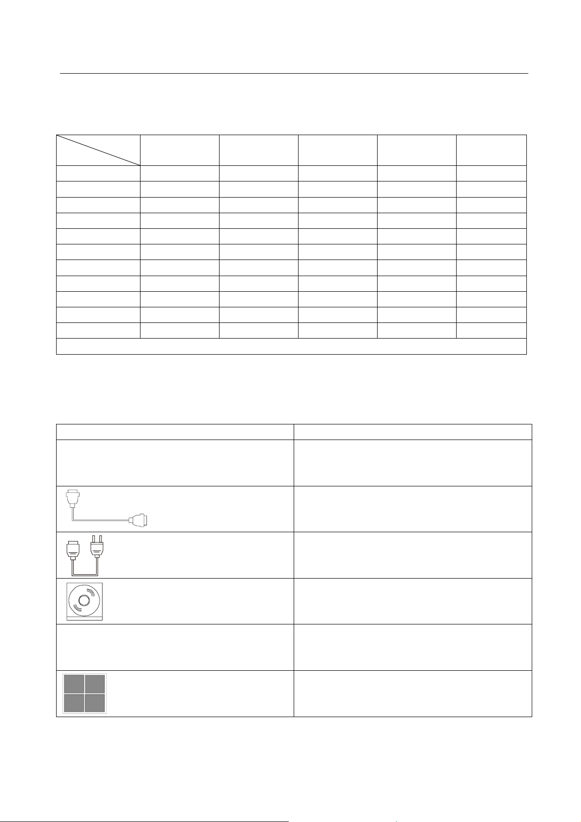
2. Packing of the Product
Pictures Description
MTX matrix switcher (with empty slot and empty
cover)
RS-232 Communication Cord
Power Supply Cord
CD with Application SWITCHER 2.0
User manual
Rubber cushion
2
PTN Electronics Limited www.PTN-electronics.com
Page 8

MTX Series Matrix Switcher
3. Installation
MTX series matrix switchers adopt metal shell and can be stacked with other device. Moreover, they
are rack-mountable enclosure and can be installed in the standard 19 inches case.
4. Front View and Rear View of the Product
4.1 Front View of the MTX200
3
PTN Electronics Limited www.PTN-electronics.com
Page 9

MTX Series Matrix Switcher
4.2 Rear View of the MTX200
4.3 Front View of the MTX400
(Crystal Buttons Version)
There are two different button in the front panel.
1: Regular buttons.
Black plastic buttons, with red LED indicating.
2: Crystal buttons.
Crystal buttons, with green back-light indicating, which can insert customized label.
4
PTN Electronics Limited www.PTN-electronics.com
Page 10

MTX Series Matrix Switcher
4.4 Rear View of the MTX400
( Maximum installed 6 cards. The cards in the pictures is only for reference. The user can change it ,
plug and play. )
4.5 Front View of the MTX500
(Crystal Buttons Version)
There are two different button in the front panel.
1: Regular buttons.
Black plastic buttons, with red LED indicating.
2: Crystal buttons.
Crystal buttons, with green back-light indicating, which can insert customized label.
5
PTN Electronics Limited www.PTN-electronics.com
Page 11

MTX Series Matrix Switcher
4.6 Rear View of the MTX500
( Maximum installed 8 cards. The cards in the pictures is only for reference. The user can change it ,
plug and play. )
Please contact us for more information: [email protected]
www.PTN-electronics.com
or visit website:
5. Changeable Cards Introduction &
Installation
5.1 Introduction of the changeable cards and slots
There are various changeable cards, which can insert to the MTX empty slot (hot-swop). It includes
different signal, such as DVI, HDMI, VGA, composite video, s-video, USB2.0, stereo audio, audio
mixer, twisted pair etc. All these card can be inserted to the MTX main unit (empty slot) by your will.
Now, there is the one by one introduction for every card.
5.1.1 MXDV4
DVI cross point matrix switcher. 4x4. (Please check the specification from 9.2.1)
It is fully compatible with HDMI (HDCP1.3, 1.2, 1.1), not supporting analogy signal.
It is embedded the EDID management technology, supporting CEC, DDC.
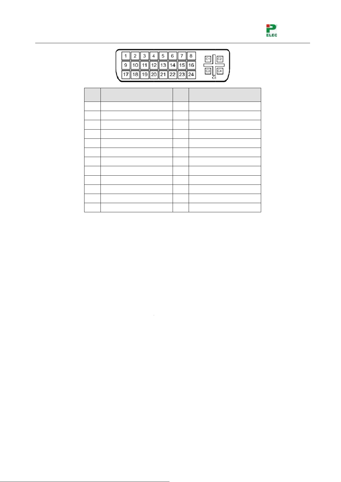
Pin Layout of the DVI-I connector (Dual-Link). (female)
6
PTN Electronics Limited www.PTN-electronics.com
Page 12
MTX Seri
E
D
c
u
e
s
H
e
a
a
S
I12345678
9
m
h
e
h
i
S
S
S
S
S
l
a
n
S
S
S
S
h
a
h
t
a
V
S
h
e
o
D
a
N
s
o
i
c
s
d
P
F
w
a
r
C
C
o
h
l
9
y
m
es Matrix
witcher
P
N
Function
PI
unction
5.1.2 MX
DVI
It is f
It is
V8
ross point
lly compati
mbedded t
T.M.D.
T.M.D.
T.M.D.
T.M.D.
T.M.D.
DDC C
DDC D
No Co
T.M.D.
1
0 T.M.D.
1
1 T.M.D.
1
2 T.M.D.
atrix switc
ble with HD
e EDID m
.Data2.Data2+
. Data 2/4
. Data 4. Data 4+
ock
ta
nect
.Data1.Data1+
.Data1/3 S
.Data3-
er 8x8. (Pl
MI (HDCP1
nagement t
13
14
hield 15
16
17
18
19
20
21
22
ield 23
24
ase check
.3, 1.2, 1.1)
echnology,
T.M.D.S.
+5V Po
Ground (
Hot Plug
T.M.D.S.
T.M.D.S.
T.M.D.S.
T.M.D.S.
T.M.D.S.
T.M.D.S.
T.M.D. S
T.M.D.S
the specific
, not suppo
upporting
Data3+
er
for +5V)
Detect
Data 0-
Data 0+
Data 0/5 S
Data5-
Data5+
Clock Shie
. Clock +
.Clock-
tion from
ting analog
EC, DDC.
ield
d
.2.1)
signal.
Plea
5.1.3 MX
HDM
It is
It is
Pin l
PTN
e check th
D4
I cross poin
mbedded t
lso compat
yout of the
lectronics
5.1.1 for t
t matrix swi
e EDID m
ble with D
HDMI conn
Limited
e introducti
cher. 4x4. (
nagement t
I signal (H
ectors(fem
n of DVI p
Please che
echnology,
CP require
le ).
7
n layout.
k the speci
upporting
)
www.
fication fro
EC, DDC.
TN-electr
9.2.1)
nics.com
Page 13
MTX Seri
E
V
b
p
a
S
u
s
P
r
gTMTMTMTMTM
M
MTMTM
M
c
M
R
+
-
+
-
+
-
P
G
l
_
T
n
k
Y
N
P
r
m
o
m
e
r
k
c
c
c
a
R
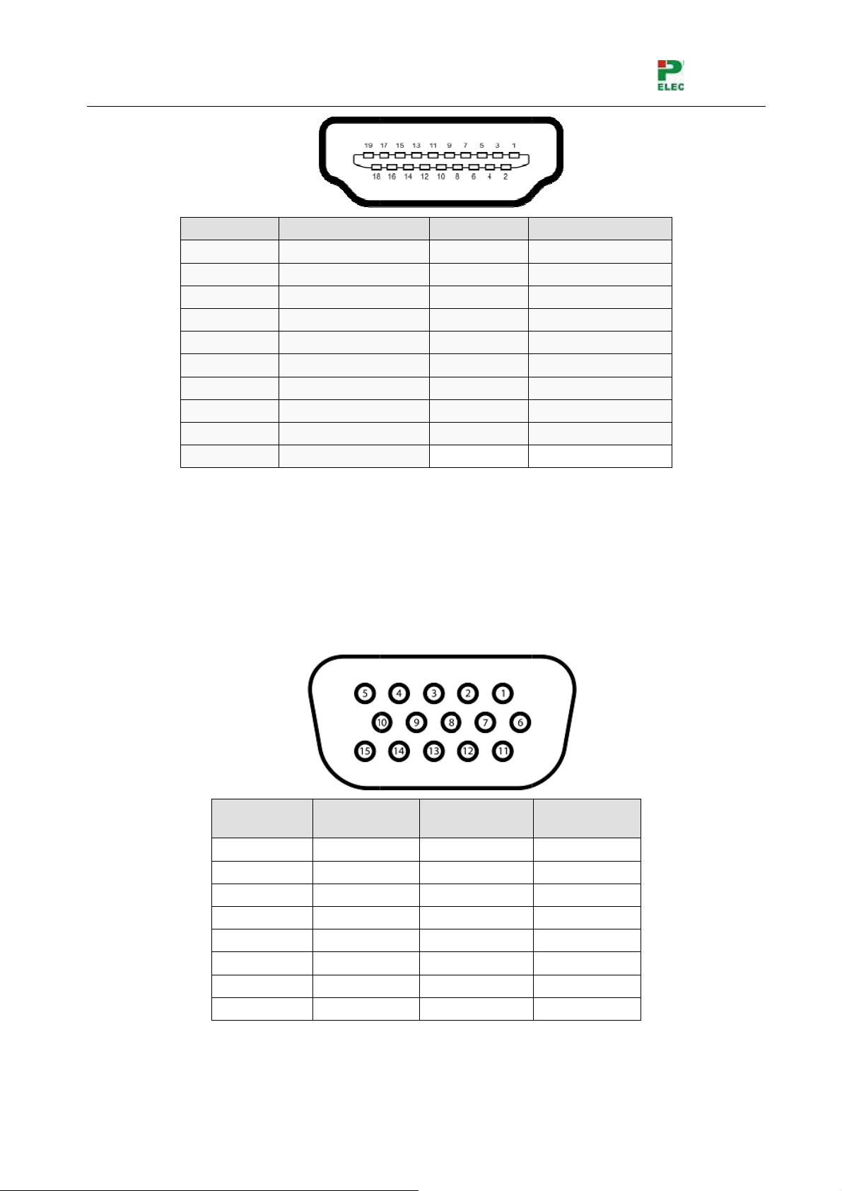
5.1.4 MX
VGA
The
Sup
es Matrix
Pin N
1
2
3
4
5
6
7
8
9
10
G4
cross point
andwidth i
orting RGB
witcher
mbe
Si
T
T
T
matrix swit
up to 350
HV, RGsB,
nal Name
DS Data 2
DS Data 2
DS Data 2
DS Data 1
DS Data 1
DS Data 1
DS Data 0
DS Data 0
DS Data 0
DS Clock+
her. 4x4. (
Hz(-3dB)
GBS, Rs
Shield
Shield
Shield
lease chec
sBs, YUV,
Pi
Numbe
20
19
18
17
16
15
14
13
12
11
the specifi
C and Co
Signal Na
SHELL
Hot Plug D
+5V Powe
Ground
DDC Data
DDC Cloc
No Conne
CEC
TMDS Clo
TMDS Clo
cation from
posite vide
e
etect
t
kk Shield
9.2.2)
o.
Pin l
yout of the
VGA conne
in Number
Pin 1
Pin 2
Pin 3
Pin 4
Pin 5
Pin 6
Pin 7
Pin 8
ctors (fema
Signal N
RED
GREEN
BLUE
ID2/RES
GND
RED_RT
GREEN
BLUE_R
e ):
ame Pin
N
RTN
N
umber
Pin 9
Pin 10
Pin 11
Pin 12
Pin 13
Pin 14
Pin 15
Signal N
KEY/PW
GND
ID0/RES
ID1/SDA
HSync
VSync
ID3/SCL
me
8
PTN
lectronics
Limited
www.
TN-electr
nics.com
Page 14
MTX Series Matrix Switcher
5.1.5 MXVG8
VGA cross point matrix switcher 8x8. (Please check the specification from 9.2.2)
The bandwidth is up to 350MHz(-3dB)
Supporting RGBHV, RGsB, RGBS, RsGsBs, YUV, YC and Composite video.
Please check the 5.1.4 for the introduction of VGA pin layout.
5.1.6 MXCV8
Composite Video cross point matrix switcher. 8x8. (Please check the specification from 9.2.2)
The bandwidth is up to 150MHz(-3dB)
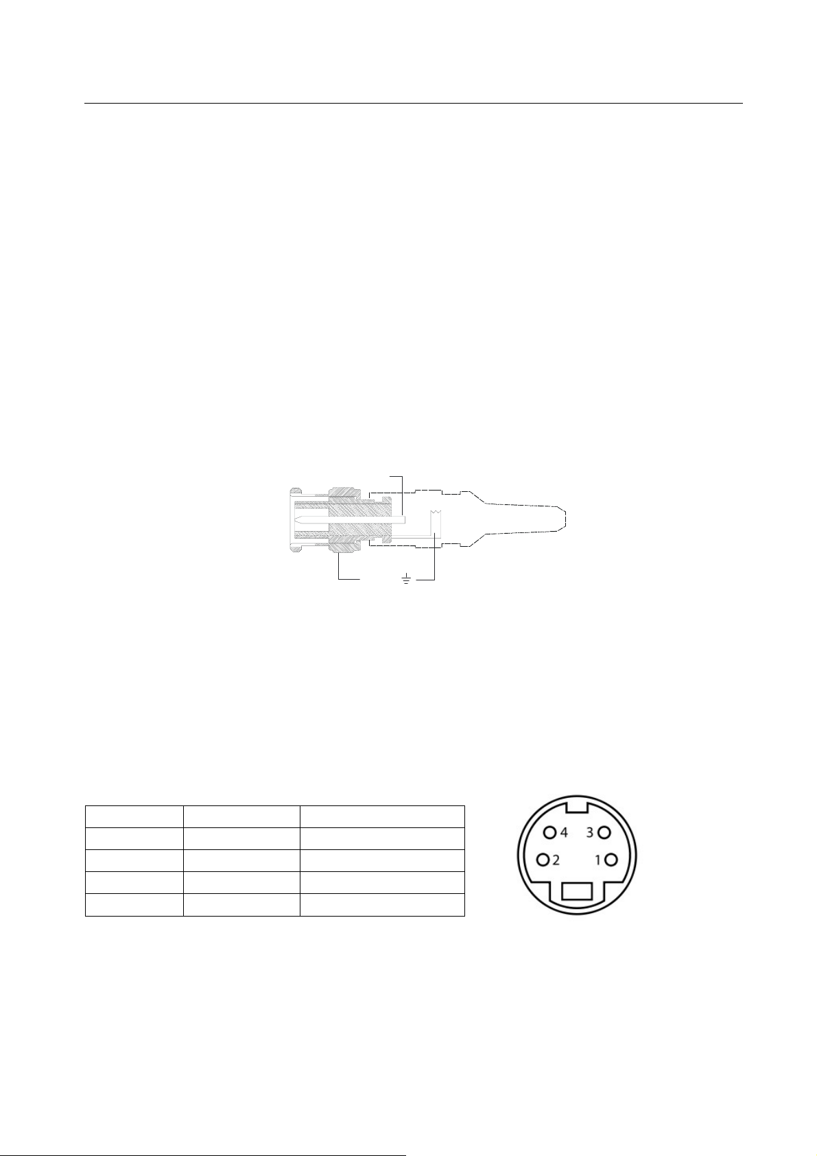
The BNC connector is shown as the figure below.
Tip (+)
( )
Sleeve
BNC Connector
5.1.7 MXSV8
S-Video cross point matrix switcher. 8x8. (Please check the specification from 9.2.2)
The bandwidth is up to 150MHz(-3dB)
Pin lay out of the S-Video connector (female):
Pin Number Signal Name Remark
Pin 1 GND Ground (Y)
Pin 2 GND Ground
Pin 3 Y Intensity (Luminance)
Pin 4 C Color (Chrominance)
5.1.8 MXAU8
Stereo Audio cross point matrix switcher. 8x8. (Please check the specification from 9.2.3)
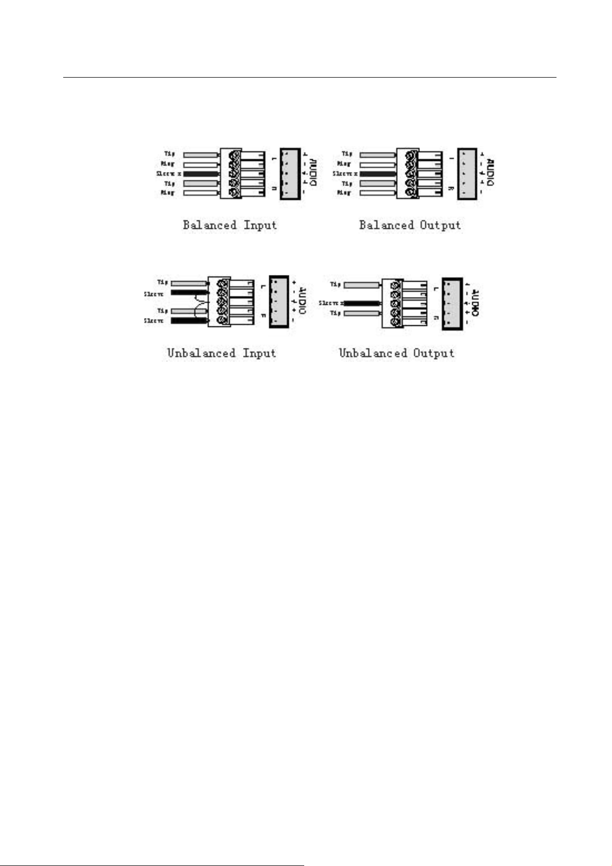
It supports the balanced/unbalanced audio, by different connection.
9
PTN Electronics Limited www.PTN-electronics.com
Page 15
MTX Series Matrix Switcher
Balanced Audio Connection:
Unbalanced Audio Connection:
5.1.9 MXUS8
USB2.0 matrix switcher. 8x8. (Please check the specification from 9.2.4)
It does not supports the cross point switching, ONLY one to one switching..
It is working compatible with USB1.0, USB1.1 and PS2.
5.1.10 MXPA8
Stereo Audio cross point matrix switcher. 8x8, and embedded the audio processor function.
(Please check the specification from 9.2.5, Please check the RS232 code from 7.2)
EQ function: Every input volume is preset-able, every output bass/treble control-able. All these EQ
function can be controlled by RS232 or TCP/IP, working with PTN PC software.
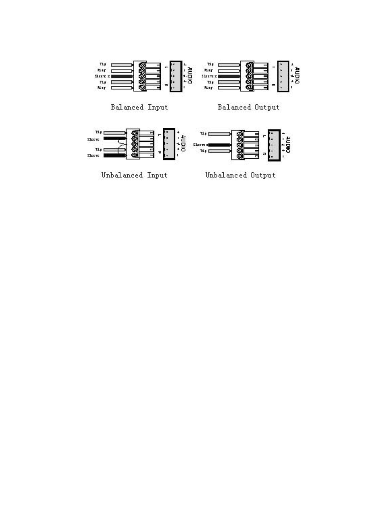
Balanced Audio: It supports the balanced/unbalanced audio, by different connection. Please check
the connection below:
Audio Mixer : The 8 output is built in the mixer function, which can mix any two or more inputs. The
mixer function can be controlled by RS232 or TCP/IP, working with PTN PC software.
10
PTN Electronics Limited www.PTN-electronics.com
Page 16
MTX Series Matrix Switcher
Balanced Audio Connection:
Unbalanced Audio Connection:
5.1.11 MXTP8
Twisted pair cross point matrix switcher. 8x8. (Please check the specification from 9.2.6)
8 inputs (4 VGA/Stereo audio and 4RJ45), 8 outputs (8 RJ45), 1 local monitor for VGA and stereo
audio.
It is working with PTN TP200 Pro (VGA/Stereo Audio twisted pair). The transmission distance is up
to 300 meters. It is built in the skew equalizer (EQ) function for each channel.
5.2 ID setting during installation
There are several slots in the rear panel of MTX main unit (chassis). The changeable card can be
inserted, and working after the ID setting.
Every slot has the defaulted ID, which is fixed after the production. The changeable card has to
match the ID of each slot.
The MTX supports the hot-swop, plug and play. When the card is inserted or removed, the RS232
port will send out the feedback codes, for indicating.
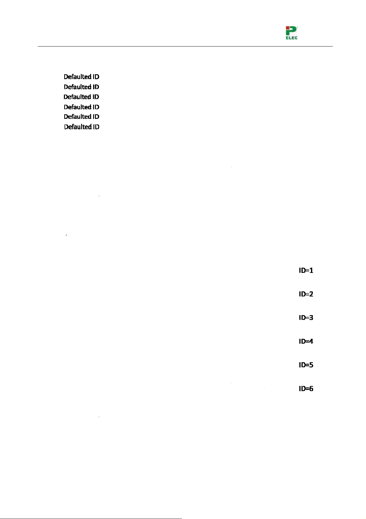
5.2.1 Defaulted ID of each slot
The defaulted ID of each slot is counting from “1”, from the top slot to the bottom slot.
We take the MTX400 as an example , The top slot is defaulted as “1”. The second slot is defaulted
as “2”, the third slot is defaulted as “3”, and so on and so forth.
Please check the picture :
11
PTN Electronics Limited www.PTN-electronics.com
Page 17
MTX Seri
E
T
t
m
c
s
M
a
e
s
S
6
0
b
e
D
u
a
e
d
u
a
2
g
e
n
e
c
d
o
n
o
a
t
p
m
o
o
h
l
P
o
o
t
(
2
o
r
o
m
a
b
a
h
y
e
k
So, i
The I
5.2.2 ID
The
adju
The
the s
Now,
es Matrix
here are
(
means the
D of MTX5
atching,
ards will b
t the card I
TX main
me as slot
we take th
witcher
slots to th
ID of MTX
0 is rangin
etween th
enable a
, the sam
nit will dete
ID. )
MTX400 a
e MTX400.
00 is rangi
from “1” t
slot and c
d work , af
as the inse
t the card,
s an exam
Their ID is
g from “1” t
“8”, from t
rd
er match t
rted slot ID.
after the ID
le:
ranging fr
“3”, from t
p to bottom
e slot ID. I
matching.
m 1 to 6, f
p to botto
.
means the
manually
om top to
.
user need
djust the c
ottom)
to manuall
rd ID , to b
It m
ans the car
code
, after the s
The
ame ID m
PTN
lectronics
ID must t
ccessful m
tching is to
Limited
be the sa
atching.
MTX200 an
e as the s
d MTX500.
12
ot. The RS
www.
32 port wil
TN-electr
l send out t
nics.com
e feedbac
Page 18
MTX Series Matrix Switcher
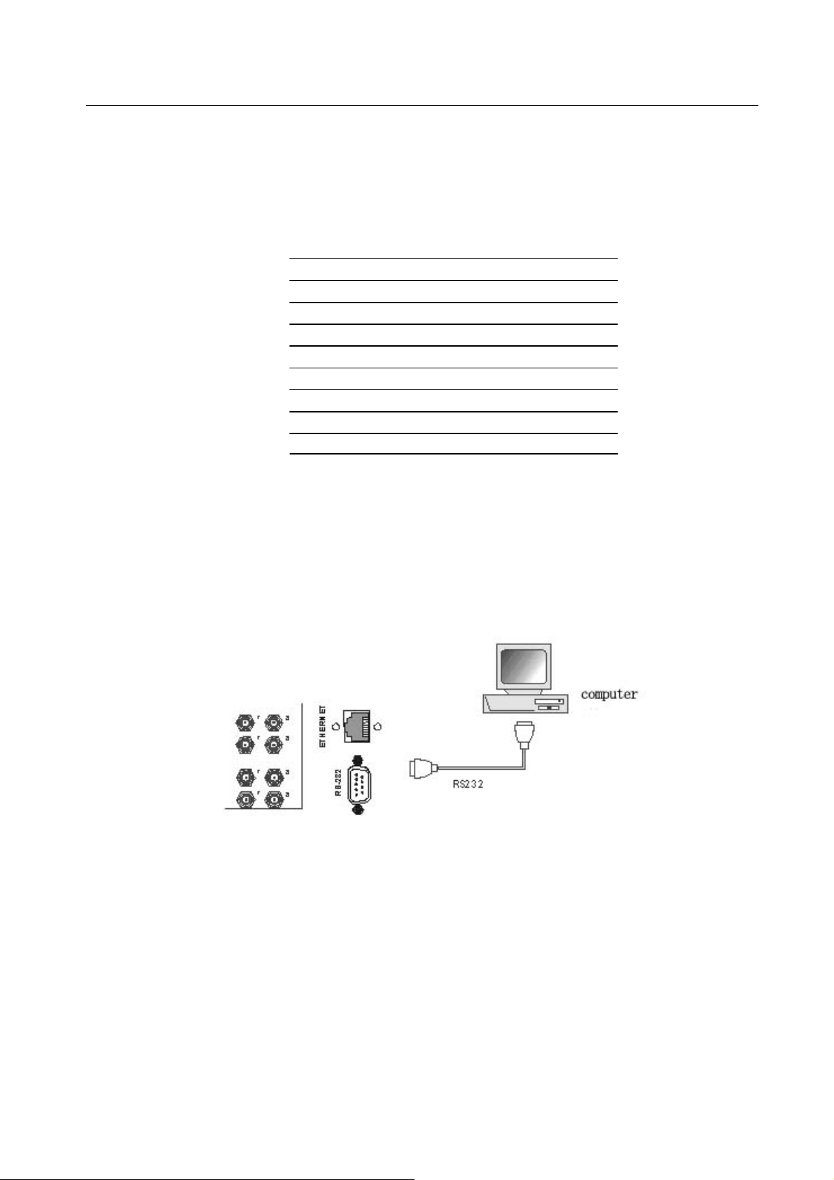
5.3 Connection of RS-232 Communication Port
Except the front control panel, the MTX matrix switcher can be control by far-end control system
or through the Ethernet control via the RS-232 communication port.
This RS-232 communication port is a female 9-pin D connector. The definition of its pins is as the
table below.
Pin No. Name Function
1 N/u Unused
2 Tx Transmit
3 Rx Receive
4 N/u Unused
5 Gnd Ground
6 N/u Unused
7 N/u Unused
8 N/u Unused
9 N/u Unused
5.3.1 Connection with Control Systems
With the RS-232 port, the MTX matrix switchers can be control by several kinds of control
systems.
5.3.2 Connection with Computer
When the switcher connects to the COM1 or COM2 of the computer with control software, users
can control it by that computer.
To control the switcher, users may use the RS232 software
F 5-1 Connection between MTX matrix switcher and the computer
5.4 Connection of TCP/IP Communication Port (Optional Function)
The MTX matrix switchers can work with the PTN model “PTNET”, to enable the TCP/IP function.
The PTNET is a programmable RCP/IP to RS232 processor, which is built in the FTP and fixed IP
address inside and working compatible with internet.
13
PTN Electronics Limited www.PTN-electronics.com
Page 19

MTX Series Matrix Switcher
5.5 System Diagram
6. Operation of the Control Panel
6.1 Front Panel Description
14
PTN Electronics Limited www.PTN-electronics.com
Page 20
MTX Series Matrix Switcher
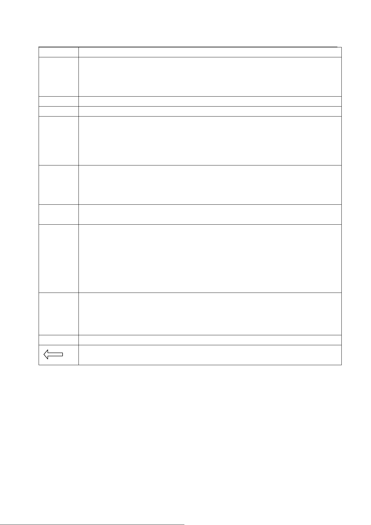
Buttons Function Description
ID selection buttons. It is the ID number of every slot. The user need to select the ID,
ID
Selection
INPUTS Input buttons. It is the number of every input channel, ranging from "1" to "8".
OUTPUTS Output buttons. It is the number of every output channel, ranging from "1" to "8".
SAVE
RECALL
DEMO
ALL
before controlling this slot(card).
Example: you want to control the second slot (card), you need to select the ID button "2"
in advance.
Saving function of preset. It means you can save the current working status as the
preset, in order to recall this function easy in the future. There are 8 presets in total,
ranging from 1~8.
Example: Press "SAVE" and press "1", the MTX will save the current status as "preset
1"
Recall function of preset. It means you can recall the saved preset, and return to some
previous working status.
Example: Press "RECALL" and press "1", the MTX will recall the working stauts of
"preset 1"
Demo function. When you press this button, the MTX will enter the demo status, routing
automaticlly, from input 1 to output 8, for all the switching testing.
All button: To transfer an input channel to all output channels or switch off all the output
channels
Example1: To transfer video and audio signals from input channel No.7 to all output
channels
Operation: Press buttons in this order “7”, “ALL”
Example2: To transfer all input signals to the corresponding output channels
respectively. In another word, to switch to this status: 1->1, 2->2, 3->3, 4->4……8->8.
Through button: To transfer the signals directly to the corresponding output channels
THROUGH
UNDO Undo button: To resume to the status before the command just performed
Example: To transfer the signals from input channel No. 3 to their corresponding output
channels
Operation: Press buttons in this order “3”, “THROUGH”
Backspace button: To backspace the latest input button
6.2 Command Format of the Switching Operation
With the front control panel, the switcher could be control directly and rapidly by pressing the buttons
under below format.
“ID selection” +“Input Channel” +“Output Channels”
“ID selection”: select the right ID, which you are going to control.
“Input Channel”: press the number of input channel to be controlled
15
PTN Electronics Limited www.PTN-electronics.com
Page 21
MTX Series Matrix Switcher
“Output Channel”: press the number of output channels to be controlled
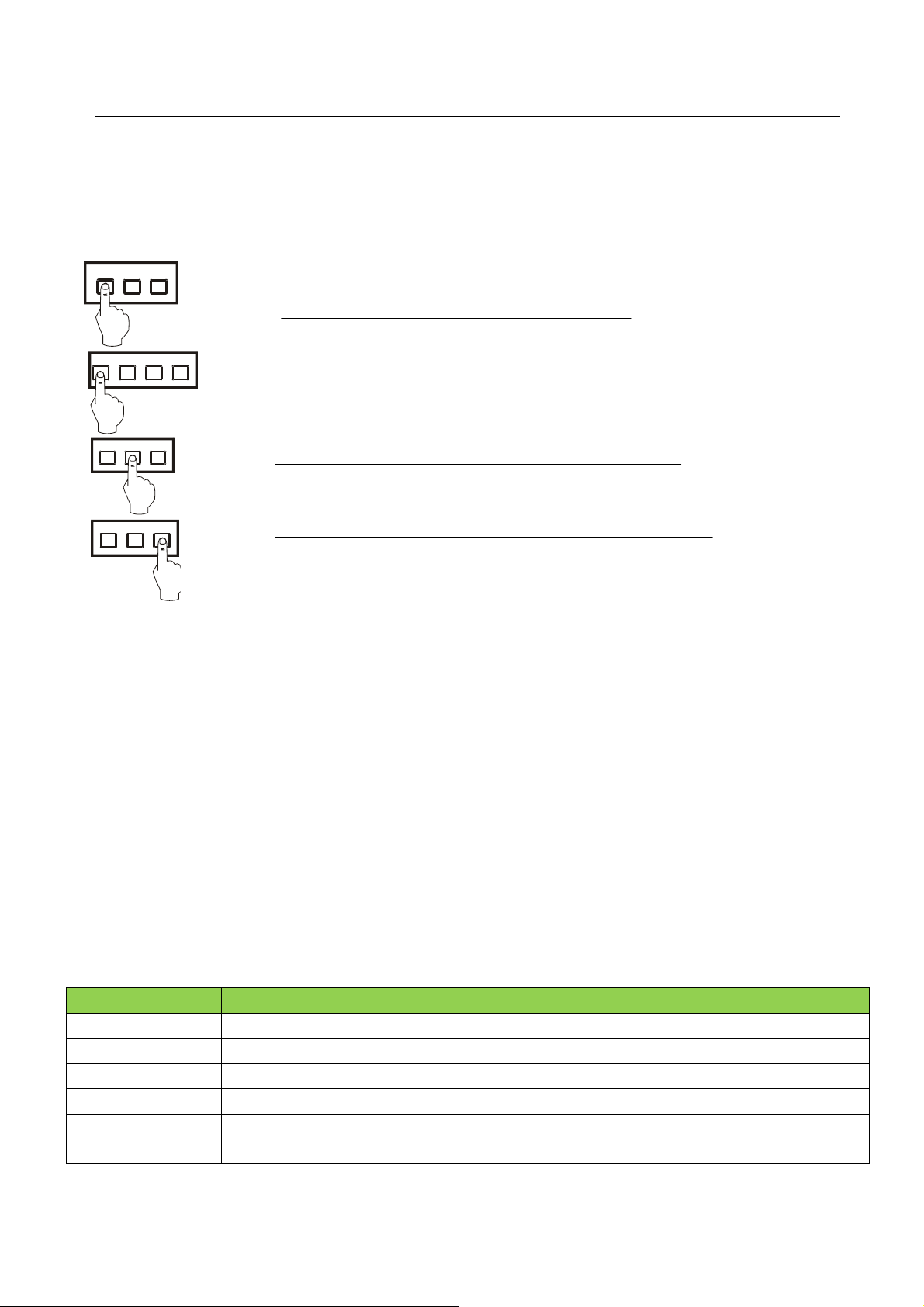
6.3 Examples of Operation
Example 1:To transfer the signal of ID”1” from input channel No.1 to output channel
No.3,4
AV AudioVideo
1342
342
342
1, Press the “1” from the ID selection menu.
2, Press the button for input channel number“1”
3,Press the button for the first output channel number “3”
4, Press the button for the second output channel number “4”
Then, switching OK ! the signal of ID”1” is switching from “1” to “3” and “4”
7. Communication Protocol and Command
Codes
7.1 RS232 codes of regular switching (not including the MXPA8)
With this command system, the RS232 software is able to control and operate the MTX Matrix with
remotely.
Communication protocol:
Baud rate: 9600 Data bit: 8 Stop bit: 1 Parity bit: none
Commands: Description
/*Type;
/%Lock;
/%Unlock;
/^Version; Inquire the version of firmware. (refer to Detail example 4)
/:MessageOff;
PTN Electronics Limited www.PTN-electronics.com
Check the system information and ID information.
Lock the keyboard of the control panel on the matrix.
Unlock the keyboard of the control panel on the matrix.
Switch off the feedback command from the com port. It will only show “switcher OK”.
(refer to Detail example 5)
16
Page 22

MTX Series Matrix Switcher
/:MessageOn; Switch on the feedback command from the com port. (refer to Detail example 6)
Demo.
Switch to the “demo” mode, 1->1, 2->2, 3->3 … and so on, every 2 seconds, and cycled
switching.
Save[Z]. Save the present operation to the pr eset command [Z]. [Z] ranges from 0 to 9. (refer to
Detail example 12)
Recall[Z]. Recall the preset command [Z]. (refer to Detail example 13)
Clear[Z]. Clear the preset command [Z]. (refer to Detail example 14)
Undo.
To cancel the previous operation.
&[Y] + Status[x]. Inquire the input channel to the output channel [x1] of [Y] card. (refer to Detail example
10)
&[Y] + Status. Inquire the input channels to the output channels one by one, of [Y] card. (refer to
Detail example 11)
&[Y] + [x]All. Transfer signal on [Y] card from input channel [x] to all output channels. (refer to Detail
example 1)
&[Y] +All#.
Transfer all input signals on [Y] card to the corresponding output channels respectively.
(refer to Detail example 2)
&[Y] +All$. Switch off all the output channels on [Y] card. (refer to Detail example 3)
&[Y] + [x]#. Transfer signal on [Y] card from the input channel [x] to the output channel [x]. (refer to
Detail example 7)
&[Y] + [x]$. Switch off the output channel [x] on [Y] card. (refer to Detail example 8)
&[Y] + [x1] B[x2].
Transfer the signal on [Y] card from the input channel [x1] to the output channel [x2].
(refer to Detail example 9)
&[Y] + [x1] B[x2],
[x3], [x4].
Transfer the signal on [Y] card from the input channel [x1] to the output channels [x2],
[x3] and [x4].
Notice 1 :
[Y] is the floating number, ranging from 0~9. It indentifies the ID of each card.
If [Y]=1, it means you are controlling the first slot.
If [Y]=3, it means you are controlling the third slot.
If [Y]=0, it means you are controlling all the slot at the same time.
If you forget to enter “&[Y]+”, the MTX will default it as “0”.
Notice 2 :
1. MXDV4 (DVI 4X4) card does not support the “video mute” function.
2. MXUS8 (USB 8X8) doesn’t support crosspoint switching. It supports one-to-one switching
only. For example, we have signal from input 1 to output 2 now, if we switch to output 4 then
output 2 will be cut off automatically.
Detail Examples:
1、 Transfer signal on [Y] card from one input channel to all output channels:
&[Y] + [x]All.
Example: To transfer signal on the second card from the input channel No.3 to all output channels.
Run Command: “&2+3All.”
17
PTN Electronics Limited www.PTN-electronics.com
Page 23

MTX Series Matrix Switcher
2、 Transfer all input signals on [Y] card to the corresponding output channels respectively:
&[Y] + All#.
Example: If the command “&1+All#” is carried out, the status of the first card will be: 1->1, 2->2,
3->3, 4->4……8->8.
3、 Switch off all the output channels on [Y] card: &[Y]+ All$.
Example: After running the command “&3+All$”, there will be no signal output on the third card.
4、 Check the version of the firmware: /^Version;
To check the version of the firmware, run command “/^Version”.
5、 Switch off the detail feedback command from the COM port: /:MessageOff;
Switch off the detail feedback information from the COM port. But, it will leave the “switch OK” as
the feedback, when you switch the matrix.
6、 Switch on the detail feedback command from the COM port: /:MessageOn;
Switch on the detail feedback information from the COM port. It will show the detail switch
information when it switches. Example: when switch 1->2 for Audio, it will feedback “A0102”.
7、 Transfer signal on [Y] card from an input channel to the corresponding output channel:
&[Y]+[x]#.
Example: To transfer signal of the fourth card from the input channel No.5 to the outp ut channel
No.5. Run Command: “&4+5#.”
8、Switch off an output channel of [Y] card: &[Y]+[x]$.
Example: To switch off the output channel No.5 on the first card. Run Command: “&1+5$.”
9、Switch the signal on [Y] card, from [x1] to [x2]: &[Y]+[x1] B[x2].
Example: To transfer the signal of the fifth card, from the input channel No.8 to the output channel
No.3,6,7. Run Command: “&5+8B3,6,7.”
10、Inquire the input channel to the output channel [x] of [Y] card: &[Y]+Status[x].
Example: To inquire the input channel to the output channel No.7 of the first card. Run Command:
“&1+Status7.”
11、Inquire the input channels to the output channels one by one, of [Y] card: &[Y]+Status.
Example: To inquire the input channels to the output channels one by one of the first card. Run
Command: “&1+Status.”
12、Save the present operation to the preset command [Z]: Save[Z].
Example: To save the present operation to the preset command No.7. Run Command: “Save7.”
13、Recall the preset command [Z]: Recall[Z].
Example: To recall the preset command No.5. Run Command: “Recall5.”
14、Clear the preset command [Z]: Clear[Z].
Example: To clear the preset command No.5. Run Command: “Clear5.”
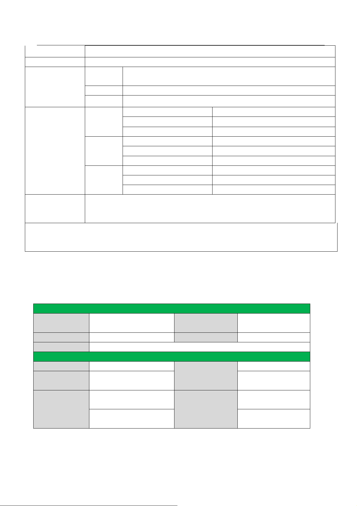
7.2 RS232 codes of MXPA8
Communication protocol:
Baud rate: 9600 Data bit: 8 Stop bit: 1 Parity bit: none
RS232
commands
PTN Electronics Limited www.PTN-electronics.com
Function Desctription
18
Page 24
MTX Series Matrix Switcher
&[Q]+ Audioinit. Initialize the Volume/Bass/Treble
&[Q]+ VOICE. Checking the level of Volume/Bass/Treble of all the channels
&[Q]+ [Y]API[x]
[x].
&[Q]+ [Z]APO[Y]
[x] [x].
&[Q]+
[x1]AND[x2],[x3]…
[x8].
[xx] is from
"00" to "60"
[xx] = [UP] Turning up the volume of input [Y]
[xx] = [DO] Turning down the volume of input [Y]
[xx] is ranging from "00" to "12" Preset the treble of output [Z]
[Y] = [H]
[xx] is ranging from "00" to "12" Preset the bass of output [Z]
[Y] = [L]
[xx] is ranging from "00" to "60" Preset the volume of output [Z]
[Y] = [A]
[xx] = [UP] Turning up the treble of output [Z]
[xx] = [DO] Turning down the treble of output [Z]
[xx] = [UP] Turning up the bass of output [Z]
[xx] = [DO] Turning down the bass of output [Z]
[xx] = [UP] Turning up the volume of output [Z]
[xx] = [DO] Turning down the volume of output [Z]
Input audio mixed. Maximum 8 channels mixed.
preset the volume of input [Y], 61 degrees
Remark:
&[Q]+ [Q] is the ID of MXPA8) . If you miss sending the "&[Q]+", the code will be sent to all
the cards.
8. Specification
8.1 Main Unit (Chassis)
Control parts
Serial control port
Intallation Rack Mountable Front panel control Buttons
Options TCP/IP control by PTNET(PTN's programmable interface)
General
Power Supply 110VAC ~ 240VAC, 50/60Hz
Temperature
Case Dimension
RS-232, 9-pin female D
connector
-20 ~ +70℃
W482.6 x H174.5 x D282mm
(MTX400)
W482.6 x H221.5 x D300mm
(MTX500)
Pin Configurations 2 = TX, 3 = RX, 5 = GND
17W (MTX400)
Power Consumption
25W (MTX500)
2.5Kg(MTX400)
Product Weight
3.5Kg (MTX500)
19
PTN Electronics Limited www.PTN-electronics.com
Page 25
MTX Series Matrix Switcher
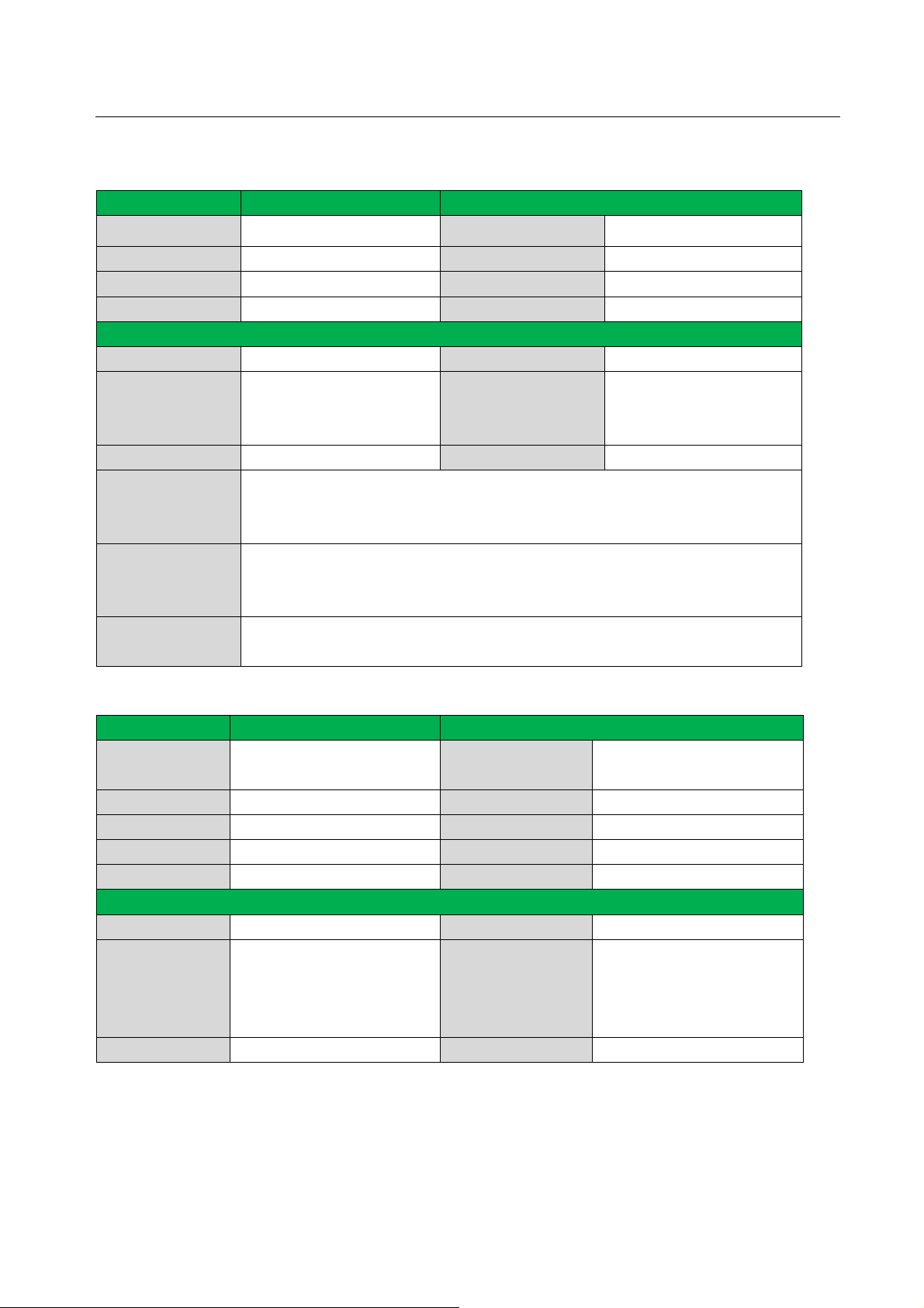
8.2 Changeable Cards
8.2.1 MXDV4, MXDV8, MXHD4
Input Output
Input 4 DVI; 8 DVI ; 4 HDMI Output 4 DVI; 8 DVI ; 4 HDMI
Input Connector Female DB24+5/HDMI Output Connector Female DB24+5/HDMI
Input Level T.M.D.S. 2.9V/3.3V output Level T.M.D.S. 2.9V/3.3V
Input Impedence 75Ω Output Impedence 75Ω
General
Gain 0 dB Bandwidth 340 MHz (10.2 Gbit/s)
DVI 1.0 standard DVI-D
Video Signal
Switching Speed 200ns (Max.) Crosstalk <-50dB@5MHz
Consumer
Electronics
Control (CEC)
EDID and DDC
HDCP
8.2.2 MXVG4, MXVG8
Input Output
Input
Input Connector Female 15 pin HD Output Connector Female 15 pin HD
Input Coupling AC coupling only Switching Type Vertical interval
Input Level 0.5 ~ 2.0Vp-p output Level 0.5 ~ 2.0Vp-p
Input Impedence 75Ω Output Impedence 75Ω
General
Gain 0 dB Bandwidth 350MHz (-3dB), fully load
Video Signal
Switching Speed 200ns (Max.) Crosstalk <-50dB@5MHz
full digital T.M.D.S signal
HDMI 1.3
Supports CED wired infrared data pass-through using the HDMI 1.3 standard
Supports Extended Display Identification Data (EDID) and Display Data
Channel (DDC) data using DVI and HDMI standards. EDID and DDC signals
are actively buffered
Compliant with High-bandwidth Digital Content Protection (HDCP) using DVI
and HDMI 1.3 standards
4 VGA
8 VGA
VGA-UXGA,RGBHV,RGBS,
RGsB, RsGsBs, component
video, S-video, and
composite video .
Max Time-delay 5nS (±1nS)
Output
Video Type
4 VGA
8 VGA
VGA-UXGA,RGBHV,RGBS,
RGsB, RsGsBs, component
video, S-video, and
composite video .
20
PTN Electronics Limited www.PTN-electronics.com
Page 26
MTX Series Matrix Switcher
c
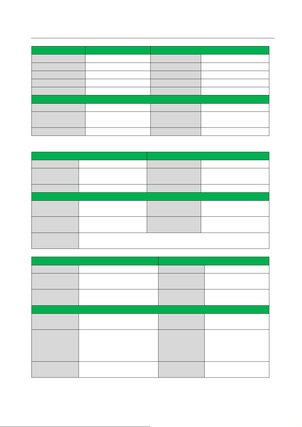
8.2.3 MXCV8, MXSV8
Input Output
Input 8 video Output 8 video
Input Connector Female RCA/S-V Output Connector Female RCA/ S-V
Input Coupling AC coupling only Switching Type Vertical interval
Input Level 0.5 ~ 2.0Vp-p output Level 0.5 ~ 2.0Vp-p
Input Impedence 75Ω Output Impedence 75Ω
General
Gain 0 dB Bandwidth 150MHz (-3dB), fully load
Video Signal c-video/s-video Video Type
Switching Speed 200ns (Max.) Crosstalk <-50dB@5MHz
NTSC3.58, NTSC4.43,
PAL,SECAM
8.2.4 MXAU8
Input Output
Input 8 stereo Output 8 stereo
Input Connector
Input Impedance >10KΩ Output Impedance 50Ω
General
Frequency
Response
Stereo Channel
Separation
Audio Bits per
Sample
3.5 mm captive screw conne
5 pole
20Hz~20KHz, ±0.5dB
>80dB@1KHz
18 bits per channel, 2 channels (L, R)
Output Connector
CMRR >90dB@20Hz~20KHz
THD + Noise
3.5 mm captive screw
connectors, 5 pole
1% @ 1 kHz, 0.3% @ 20
kHz at nominal level
8.2.5 MXPA8
Input Output
Input 8 stereo Output 8 stereo
Input Connector
Input Impedance >10KΩ
General
Mixer Processor Built in DSP effects
Input Volume 61 degrees controllable/preset Output Volume
Frequency
Response
3.5 mm captive screw connectors,
pole
20Hz~20KHz, ±0.5dB
Output Connector
Output
Impedance
Mixer Max.
Output Gain
CMRR >90dB@20Hz~20KHz
3.5 mm captive screw
connectors, 5 pole
50Ω
21 dB
61 degrees
controllable/preset
13 degrees Bass/Treble
controllable/preset
21
PTN Electronics Limited www.PTN-electronics.com
Page 27
MTX Series Matrix Switcher
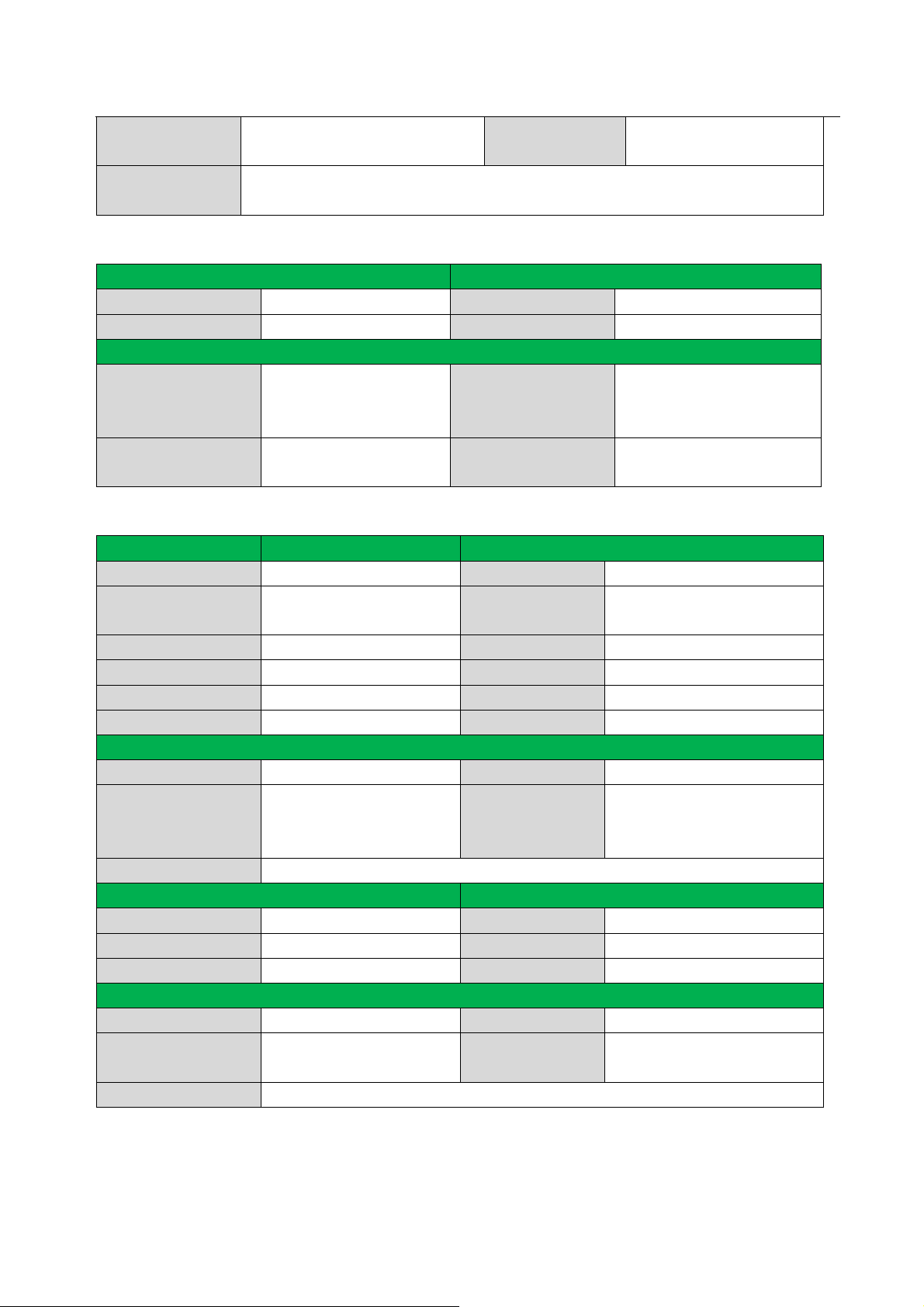
Stereo Channel
Separation
Audio Bits per
Sample
>80dB@1KHz
18 bits per channel, 2 channels (L, R)
THD + Noise
1% @ 1 kHz, 0.3% @ 20
kHz at nominal level
8.2.6 MXUS8
Input Output
Input 8 USB2.0 Output 8 USB2.0
Input Connector USB-A female connector Output Connector USB-A female connector
General
480Mbps, bidirectional
Gain 0 dB Bandwidth
Signal Type
USB2.0 (Universal Serial
Bus)
Switching Speed 200ns (Max.)
communication. Supporting
Hot Swap
8.2.7 MXTP8
Video Input Video Output
Input 4 VGA, 4 RJ45 Output 1 VGA, 8 RJ45
Input Connector
Input Level 0.5 ~ 2.0Vp-p output Level 0.5 ~ 2.0Vp-p
Input Impedence 75Ω Output Impedence 75Ω
Horizontal Frequency 15 Khz to 130Khz Switching Type Vertical interval
Vertical Frequency 30Hz to 150 Hz Return Loss <-30dB@ 5MHz
Video General
Gain 0 dB Bandwidth 450MHz (-3dB), fully load
Video Signal
Crosstalk -55dB@ 10MHz,-45dB@ 30MHz,-37dB@ 100MHz
Audio Input Audio Output
Input 4 stereo,unbalanced Output 1 stereo,unbalanced
Input Connector 3.5mm mini jack for audio Output Connector 3.5mm mini jack for audio
Input Impedance >10KΩ Output Impedance 50Ω
Audio general
Frequency Response 20Hz ~ 20KHz ± 1dB CMRR >90dB@20Hz~20KHz
Stereo Channel
Separation
S/N >70 dB at maximum output(unweighted)
Female 15 pin HD ,female
RJ45
Composite video, YC,
YUV, RGsB, RGBS,
RsBsGs, RGBHV
>80dB@1KHz
Output Connector
Switching Speed 200ms (Max.)
THD + Noise
Female 15 pin HD, female
RJ45
0.15% @ 1 kHz at nominal
level
22
PTN Electronics Limited www.PTN-electronics.com
Page 28

MTX Series Matrix Switcher
9. Troubleshooting & Maintenance
1) When the output image in the destination device connected to the MTX Matrix has ghost, such as
the projector output with ghost, please check the projector’s setting or try another high quality
connection cord.
2) When there is a color losing or no video signal output, it may be the unmatched RGBHV connector
order between the input and output end.
3) When the remote controller doesn’t works:
A. Maybe the battery is run out of, please change a new one.
B. Maybe the controller is broken, please ask the dealer to fix it.
4) When user can not control the MTX Matrix by computer through its COM port, please check the
COM port number in the software and make sure the COM port is in good condition.
5) When switching , the beeper beeps but without any output image:
A. Check with oscilloscope or multimeter if there is any signal at the input end. If there is no
signal input, it may be the input connection cord broken or the connectors loosen.
B. Check with oscilloscope or multimeter if there is any signal at the output end. If there is no
signal output, it may be the output connection cord broken or the connectors loosen.
C. Please make sure the destination device is exactly on the controlled output channel
D. If it is still the same after the above checking, it may be something wrong in the switcher.
Please send it to the dealer for fixing.
6) If the output image is interfered, please make sure the system is earthed well.
7) If the static becomes stronger when connecting the BNC connectors, it may be due to the incorrect
earthing of the power supply, Please earth it again correctly, and otherwise it would bring damage
to the switcher or shorten its natural life.
8) If the Matrix can not be controlled by the keys on the front panel, RS232 port or remote controller,
the host may has already been broken. Please send it to the dealer for fixing.
23
PTN Electronics Limited www.PTN-electronics.com
 Loading...