

PTN HDBT44-N User Manual
HDBT44-N
HDBaseT 4x4 Matrix Swi t cher
All Rights Reserved
Version: HDBT44-N_2015V1.5
User Manual

HDBaseT 4x4 Matrix Switcher-N
PTN Electronics Limited www.PTN-electronics.com
SAFETY PRECAUTIONS
To insure the best from the product, please read all instructions carefully before using
the device. Save this manual for further reference.
Unpack the equipment carefully and save the original box and packing material for
possible future shipment
Follow basic safety precautions to reduce the risk of fire, electrical shock and injury
to persons.
Do not dismantle the housing or modify the module. It may result in el ectrical shock
or burn.
Using supplies or parts not meeting the products’ specifications may cause damage,
deterioration or malfunction.
Refer all servicing to qualified service personnel.
To prevent fire or shock hazard, do not expose the unit to r ai n, m ois ture or install this
product near water.
Do not put any heavy items on the extension cable in case of extrusion.
Do not remove the housing of the devic e as opening or removing housing may
expose you to dangerous voltage or other hazards.
Install the device in a place with fine ventilation to avoid damage caused by
overheat.
Keep the module away from liquids.
Spillage into the ho usi ng m ay resul t in f ir e, e lec tric al s ho ck, or equipment damage. If
an object or liquid falls or spills on to the housing, unplug the module immediately.
Do not twist or pull by force ends of the optical cable. It can cause malfunction.
Do not use liquid or aerosol cleaners to clean this unit. Always unplug the power to
the device before cleaning.
Unplug the power cord when left unused for a long perio d of time.
Information on disposal for scrapped devices: do not burn or mix with general
household waste, please treat them as norm al ele ctri cal wastes.

HDBaseT 4x4 Matrix Switcher-N
NOTICE: Please read this user manual carefully before using this product. Pictures
shown in this manual are for reference only, different model and specifications are
subject to real product.
This is a manual for HDBaseT 4x4 Matrix Switcher-N. It can also be applied to
HDBaseT 4x4 Matrix Switcher with little adjustment. “N” stands for the T C P/IP port.
This manual is only for operation instruction only, not for any maintenance usage.
The functions described in this version are updated till January 2015. Any changes
of functions and parameters since then will be informed separately. Please refer to
the dealers for the latest details.
All rights reserved. No part of this publication may be copied or reproduced without
permission.
All product function is valid till 2015-01-30.

HDBaseT 4x4 Matrix Switcher-N
Contents
1. Introduction ................................................................................................................. 1
1.1 Introduction to the HDBaseT 4x4 Matrix Switcher-N ......................................... 1
1.2 Features ............................................................................................................ 1
1.3 Package List ...................................................................................................... 1
2. Product Appearan ce ................................................................................................... 2
2.1 Front Panel ........................................................................................................ 2
2.2 Rear Panel ......................................................................................................... 3
2.3 Connection with RS232 Communication Port .................................................... 4
2.4 Twisted Pair Cable Connection .......................................................................... 5
3. System Connection ..................................................................................................... 5
3.1 Usage Precautions ............................................................................................ 5
3.2 System Diagram ................................................................................................ 6
3.3 Connection Procedure ....................................................................................... 6
3.4 System Applications .......................................................................................... 7
4. Application Solution .................................................................................................... 7
5. System Operations ..................................................................................................... 9
5.1 Button Control .................................................................................................... 9
5.2 IR Control .......................................................................................................... 9
5.2.1 Usage of IR Remote .............................................................................. 10
5.2.2 IR Operations ........................................................................................ 10
5.3 RS232 Control ................................................................................................. 14
5.3.1 RS232 Commands ................................................................................ 14
5.3.2 Control the HDBaseT 4x4 Matrix Switcher-N ......................................... 19
5.3.3 Control 3rd-Party Device from Local ...................................................... 20
5.3.4 Bi-directional RS232 Control ................................................................. 20
5.4 TCP/IP Control................................................................................................. 21
5.4.1 Control Modes ....................................................................................... 21
5.4.2 Control HDBaseT 4x4 Matrix Switcher-N via TCP/IP commun ication
software .......................................................................................................... 23
5.4.3 TCP/IP Confi guration ............................................................................. 24
5.5 USB Firmware Updati ng .................................................................................. 24
6. Specification ............................................................................................................. 25
7. Panel Drawing .......................................................................................................... 26
8. Troubleshooting & Maintenance ............................................................................... 27
9. After-s ales Service .................................................................................................... 28

HDBaseT 4x4 Matrix Switcher-N
1
1. Introduction
1.1 Introduction to the HDBaseT 4x4 Matrix Switcher-N
HDBaseT 4x4 Matrix Switcher-N includes 4 HDMI inputs, 4 HDBaseT outputs, 2 local
HDMI outputs, 4 de-em bedded stereo audio & 4 de-embedded digital audio outputs.
It enables cross-point switching from any input to any output, and supports high
resolution 1080P, 1080p 3D. HDBaseT output ports can work with HDMI PoC Twisted
Pair Receiver, to transmit HDMI, IR, RS232 and PoC over a Cat5e/Cat6 cable. And its
transmission distanc e can up to 60 meters.
1.2 Features
Support 1080P@60Hz & 1080p 3D.
HDCP Compliant and DVI compatible, supporting HDMI 1.4a & DVI1.0.
Powerful EDID&HDCP management.
HDBaseT outputs, to transmit HDMI, IR&RS232 to 60 meters long distance over a
Cat5E/6 cable.
Support PoC, provides power for all the receivers connected to HDBaseT outputs.
Support multiple control ways, including front panel buttons, RS232, IR and optional
TCP/IP control (works with TCPUDP).
IR OUT signal switching follow with video signal, can also be separated from video
switching.
Support remote control fr om receiver by IR& RS232.
Support centralized IR control to control all the remote display devices.
Support PCM, Dolby, and DTS5.1 surround.
LCD indicator shows connection status , s witching status, HDCP status, and output
resolution.
1.3 Package List
1 x HDBaseT 4x4 Matrix Switcher-N
2 x Mounting ears
10 x Screws (white color)
1 x RS232 cable
4 x IR converting cable
8 x Pluggable Terminal Blocks
4 x Plastic cushions
1 x IR remote
1 x Power adapter (DC 48V)
1 x Power cord
1 x User manual
Notes:Please confirm if t he product a nd the accessories are all included, if not, pl ease
contact with the dealers.

HDBaseT 4x4 Matrix Switcher-N
2
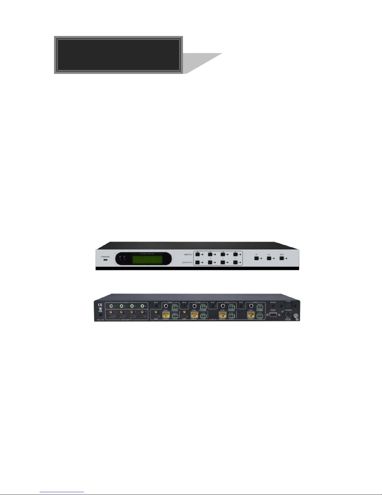
2. Product Appearance
2.1 Front Panel
No. Name Description
① Firmware Micro USB port for firmware update.
②
Power
Indicator
Illuminate red when power on.
③ IR Receiver In-built IR sensor, receive control signal from IR remote.
④ LCD Screen Shows real-time syst e m st atus.
⑤
INPUTS/
Menu
buttons
Normal mode: Input buttons, ranging from "1" to "4".
Inquiry mode: Press “AV” and hold for more than 3 seconds
to enter this mode. Dial to change different menus,
to change different channels.
⑥
Function
buttons
AV synchronal button: To transfer AV and IR signal (from IR
OUT port) synchronously by the switcher.
Note: The 4 IR OUT ports correspond with the 4 HDMI
INPUT ports separately.
Example: To transfer both AV and IR signals from Input 1
to Output 3.
Operation: Press buttons in this order “Input 1”, “AV”,
“Output 3”.
ALL outputs button: To transfer one input to all outputs .
Example: To transfer both A V and IR signals from Input 1
to all output channel s .
Operation: Press buttons in this order “Input 1”, “ALL”.
EDID management button: manually capture and learn the
EDID data from output device.
Example: Input 2 captures and learns the EDID data from
Output 4.
Operation: Press buttons in this order “EDID”, “Input 2”,
“Output 4”.

HDBaseT 4x4 Matrix Switcher-N
3
⑦ OUTPUTS
Output buttons, rangi ng from " 1" to "4", correspond to the 4
HDBaseT outputs ports.
With the front control panel, the switcher could be controlled directly and rapidly by
pressing the buttons in this order: “Input Channel” + “AV” + “Output Channel”
“Input Channel”: Fill with the number of input channel to be controlled.
“Output Channel”: Fill with the number of output channels to be controlled.
2.2 Rear Panel
No.
Name
Description
① IR ALL IN
IR control signal input port, connect with IR receiver, pass
through to all the HDBaseT ports to control remote devices.
②
HDMI
INPUTS
HDMI input ports, 4 in total, type A female HDMI connector,
connect with HDMI input source devices.
③ IR OUT
Connect with IR transmitter, to emit the IR signal sent from the
HDBaseT ports of the far-end Receiver. These IR OUTs m ake
up an IR matrix with the IR INs on the HDBaseT receivers, and
all IR signals can be switched
synchronously with the AV
signal, or separately switched.
④ OUTPUTS
IR IN: Connect with IR receiver, fixed IR input for the output,
cannot be switched separately. It makes up an IR bi-directional
transmission with the IR OUT on the corresponding HDBaseT
receiver.
HDMI: HDMI output port, connect with HDMI displayers,
deliver same input signals with HDBaseT ports, split HDMI
output for local monitoring.
COAX: HD MI de-embedded digital audio output.
HDBaseT: Works with HDBaseT receivers, such as the HDMI
HDBaseT 4x4 Matrix Switcher-N
4
twisted pair receiver & HDMI PoC twisted pair receiver. It can
extend AV , IR and R S232 s ign al t o 60 m di sta nce . Meanwhile, it
can provide power for the receivers which support PoC.
RS232: Serial port to communicate with the RS232 port on
corresponding HDBaseT receiver. When controlled by
HDBaseT receiver, the communication protocol must be the
same with the HDBaseT 4x4 Matri x Switcher-N.
AUDIO: HDMI de-embedded stereo audio output
⑤ RS232
Serial port for unit control, 9-pin female co nne ctor, connects
with control device such as a PC.
⑥
Power
Indicator
Illuminate red when powered on.
⑦ 48V DC Connect with 48V DC power adaptor.
⑧ GROUND Connect to grounding, make the unit ground well.
⑨ TCP/IP TCP/IP port for unit control, optional function.
⑩ IR EYE
Connect with extended IR receiver, use the IR remote to
control the HDBaseT 4x4 Matrix Switcher-N.
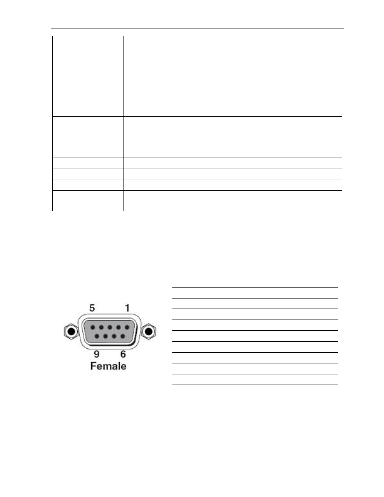
2.3 Connection with RS232 Communication Port
Except the front control panel, the HDBaseT 4x4 Matrix Switcher-N can be controlled
by far-end control system through the RS232 communication port. This RS232
communication port is a female 9-pin D connector. The definition of its pins is listed in
the table below.
No. Pin Function
1 N/u Unused
2 Tx Transmit
3 Rx Receive
4 N/u Unused
5 Gnd Ground
6 N/u Unused
7 N/u Unused
8 N/u Unused
9 N/u Unused
HDBaseT 4x4 Matrix Switcher-N
5
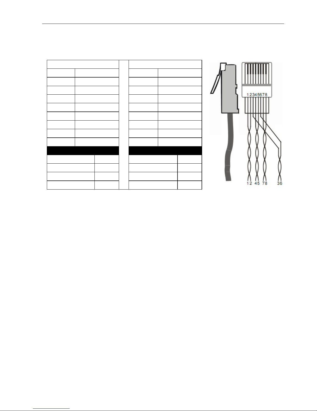
2.4 Twisted Pair Cable Conn ection
The cables for HDBaseT ports must be straight-through ones, using T568A or T568B
standard. The connectors can be T568A or T568B, but both sides must be the same.
3. System Connection
3.1 Usage Precaution s
1) System should be installed in a clean environment and has a prop temperatur e and
humidity.
2) All of the power switches, plugs, sockets and power cords should be insulated and
safe.
3) All devices should be connected before power on.
TIA/EIA T568A
TIA/EIA T568B
Pin Cable color Pin Cable color
1
green white
1
orange white
2 green 2 orange
3
orange white
3
green white
4 blue 4 blue
5
blue white
5
blue white
6 orange 6 green
7
brown white
7
brown white
8 brown 8 brown
1st Ground 4--5 1st Ground 4--5
2nd Ground
3--6
2nd Ground
1--2
3rd Group 1--2 3rd Group 3--6
4th Group
7--8
4th Group
7--8
HDBaseT 4x4 Matrix Switcher-N
6
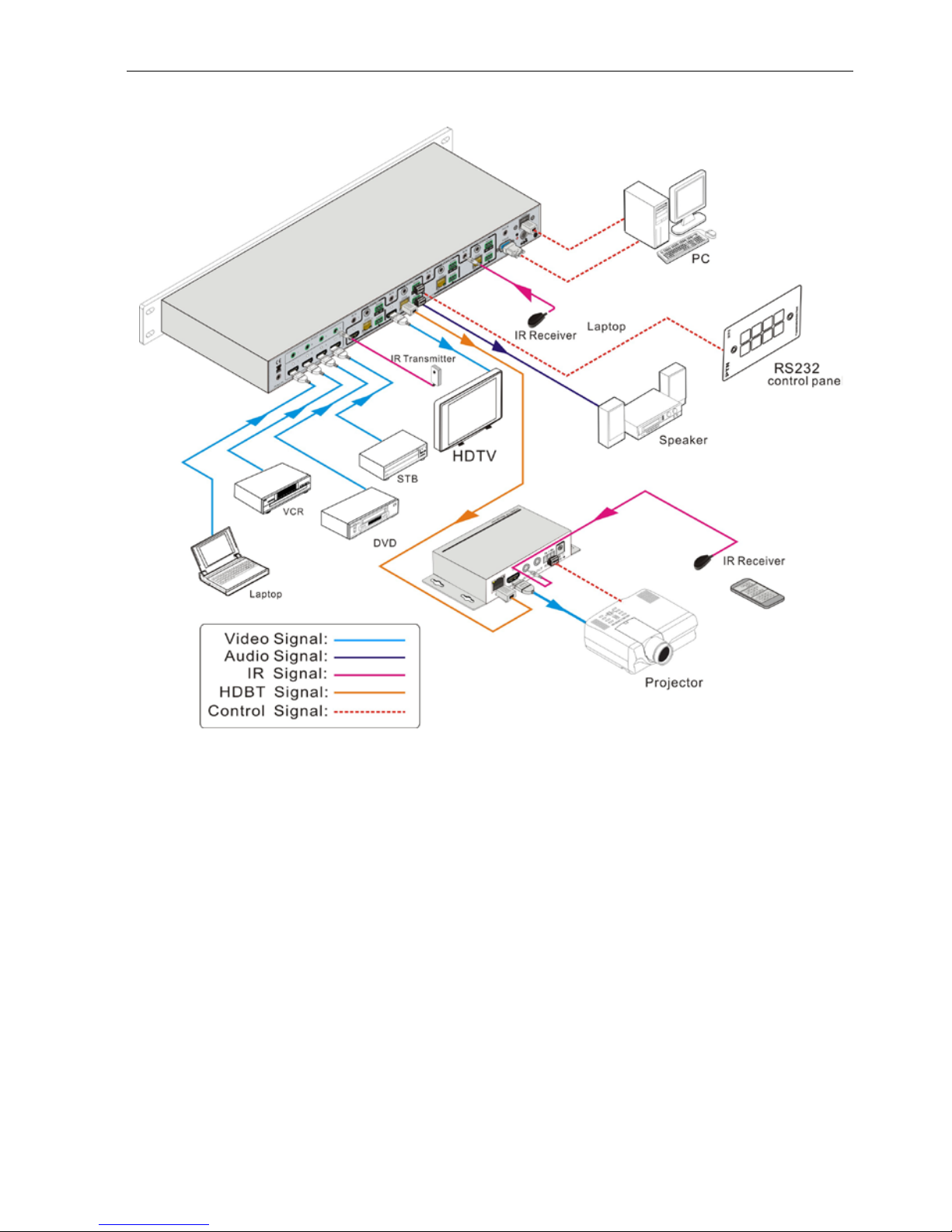
3.2 System Diagram
3.3 Connection Procedure
1) Connect HDMI source devices (e.g. DVD) to HDMI input ports of the HDBaseT 4x4
Matrix Switcher-N with HDMI cables.
2) Connect HDMI displayers (e.g. HDTV) to HDMI output ports of the HDBaseT 4x4
Matrix Switcher-N with HDMI cables.
3) Connect speakers/ earphones to AUDIO output ports (3-pin captive screw
connectors).
4) Connect the HDBaseT ports of HDBas eT receiver and the HDBaseT 4x4 Matrix
Switcher-N with twi s ted pair.
5) Connect the RS232 port (9 pin female D) of the HDBaseT 4x4 Matrix Switcher-N
with control device (e.g. PC).
6) Connect the RS232 port of the device to be controlled to the RS232 port of the
HDBaseT Receiver or HDBaseT 4x4 Matrix Switcher-N. The control sig nal can be
transmitted bi-directionally.
 Loading...