

Page 1

www.PTN-electronics.com
FMX12
Single Plug-in Card Matrix Switcher
All Rights Reserved
Version: FMX12_2016V1.1
User Manual
Page 2

Single Plug-in Card Matrix Switcher
PTN Electronics Limited www.PTN-electronics.com
Preface
Read this user manual carefully before using this product. Pictures shown in this manual
is for reference only, different model and specifications are subject to real product.
This manual is only for operation instruction only, not for any maintenance usage. The
functions described in this version are updated till January 2016. Any changes of
functions and parameters since then will be informed separately. Please refer to the
dealers for the latest details.
All product function is valid till 2016-1-12.
Trademarks
Product model, PTN and its logo are trademarks of PTN Electronics Limited.
Any other trademarks mentioned in this manual are acknowledged as the properties of
the trademark owner. No part of this publication may be copied or reproduced without
the prior written consent of PTN Electronics Limited.
FCC Statement
This equipment generates, uses and can radiate radio frequency energy and, if not
installed and used in accordance with the instructions, may cause harmful interference
to radio communications. It has been tested and found to comply with the limits for a
Class B digital device, pursuant to part 15 of the FCC Rules. These limits are designed
to provide reasonable protection against harmful interference in a commercial
installation.
Operation of this equipment in a residential area is likely to cause interference, in which
case the user at their own expense will be required to take whatever measures may be
necessary to correct the interference
Any changes or modifications not expressly approved by the manufacture would void
the user’s authority to operate the equipment.
Page 3

Single Plug-in Card Matrix Switcher
PTN Electronics Limited www.PTN-electronics.com
SAFETY PRECAUTIONS
To insure the best from the product, please read all instructions carefully before using
the device. Save this manual for further reference.
Unpack the equipment carefully and save the original box and packing material for
possible future shipment
Follow basic safety precautions to reduce the risk of fire, electrical shock and injury
to persons.
Do not dismantle the housing or modify the module. It may result in electrical shock
or burn.
Using supplies or parts not meeting the products’ specifications may cause damage,
deterioration or malfunction.
Refer all servicing to qualified service personnel.
To prevent fire or shock hazard, do not expose the unit to rain, moisture or install this
product near water.
Do not put any heavy items on the extension cable in case of extrusion.
Do not remove the housing of the device as opening or removing housing may
expose you to dangerous voltage or other hazards.
Install the device in a place with fine ventilation to avoid damage caused by
overheat.
Keep the module away from liquids.
Spillage into the housing may result in fire, electrical shock, or equipment damage. If
an object or liquid falls or spills on to the housing, unplug the module immediately.
Do not twist or pull by force ends of the optical cable. It can cause malfunction.
Do not use liquid or aerosol cleaners to clean this unit. Always unplug the power to
the device before cleaning.
Unplug the power cord when left unused for a long period of time.
Information on disposal for scrapped devices: do not burn or mix with general
household waste, please treat them as normal electrical wastes.
Page 4

Single Plug-in Card Matrix Switcher
PTN Electronics Limited www.PTN-Electronics.com
Contents
1. Introduction ................................................................................................................. 1
1.1 Introduction to FMX12 ....................................................................................... 1
1.2 Features ............................................................................................................ 1
1.3 Package List ...................................................................................................... 1
2. Panel Description ........................................................................................................ 2
2.1 FMX12 ............................................................................................................... 2
2.1.1 Front Panel .............................................................................................. 2
2.1.2 Rear Panel............................................................................................... 3
2.2 Signal Cards ...................................................................................................... 4
2.2.1 FMX-ITP& FMX-OTP ............................................................................... 4
2.2.2 FMX-ISD& FMX-OSD .............................................................................. 5
2.2.3 FMX-IVG& FMX-OVG ............................................................................. 6
2.2.4 FMX-IDV& FMX-ODV .............................................................................. 7
2.2.5 FMX-IHD& FMX-OHD ............................................................................. 8
3. System Connection ................................ ................................ ................................ ... 10
3.1 Usage Precautions .......................................................................................... 10
3.2 System Diagram .............................................................................................. 10
3.3 Connection Procedures ................................................................................... 11
3.4 Application ....................................................................................................... 11
4. Operations ................................................................................................................ 12
4.1 Front Panel Control ......................................................................................... 12
4.1.1 Switching I/O connection ....................................................................... 12
4.1.2 EDID Learning ....................................................................................... 12
4.1.3 Inquiry .................................................................................................... 13
4.1.4 Clear operation ...................................................................................... 13
4.2 IR Control ........................................................................................................ 14
4.3 RS232 Control ................................................................................................. 14
4.3.1 Installation/uninstallation of RS232 Control Software ............................ 14
4.3.2 Basic Settings ........................................................................................ 14
4.3.3 RS232 Communication Commands ...................................................... 16
Page 5

Single Plug-in Card Matrix Switcher
PTN Electronics Limited www.PTN-Electronics.com
4.4 TCP/IP Control................................................................................................. 23
4.4.1 Control Modes ....................................................................................... 23
4.4.2 Control via TCP/IP communication software ......................................... 24
4.4.3 Control via web-based GUI.................................................................... 25
4.4.4 Port Management .................................................................................. 30
5. Firmware Upgrade .................................................................................................... 31
6. Specification ............................................................................................................. 32
6.1 Main Unit ......................................................................................................... 32
6.2 Signal Cards .................................................................................................... 32
6.2.1 FMX-ITP& FMX-OTP ............................................................................. 32
6.2.2 FMX-ISD& FMX-OSD ............................................................................ 33
6.2.3 FMX-IVG& FMX-OVG ........................................................................... 33
6.2.4 FMX-IDV& FMX-ODV ............................................................................ 33
6.2.5 FMX-IHD& FMX-OHD ........................................................................... 34
7. Panel Drawing .......................................................................................................... 35
8. Troubleshooting & Maintenance ............................................................................... 36
9. After-sales Service ................................................................ ................................ .... 37
Page 6

Single Plug-in Card Matrix Switcher
PTN Electronics Limited 1 www.PTN-Electronics.com
1. Introduction
1.1 Introduction to FMX12
FMX12 is a high-performance seamlessly AV modular matrix switcher providing 12
flexible PCIE slots for single VGA/ DVI/ HDBaseT input/ output cards.
With its advanced modularization design, FMX12 can make up a 11x1~1x11 matrix of
HDMI, DVI, HDBaseT, VGA or their any combinations (count with one). All the cards
support plug-and-play. It supports different video signals with seamless cross switching.
Every video or audio signal is transmitted and switched independently to decrease
signal attenuation. The switcher can handle all the audiovisual management, including
the switching, driving, scaling etc.
1.2 Features
12 card slots for flexible input/ output combination
Comprehensive signal card compatibility: DVI/ SDI/ VGA/ HDBT
Automatically recognize input/ output signal card
Powerful EDID management
UPnP enables quick-connection to GUI
HDCP Compliant
Seamless AV distribution through different AV signal
Controllable via front panel buttons, IR, RS232 & TCP/IP
Adjustable output resolution
Online firmware upgrade via USB port
1.3 Package List
1 x FMX12
1 x IR Receiver
1 x IR Remote
2 x Pluggable Terminal Blocks
4 x Plastic cushions
1 x Power Cord
1 x User Manual
Signal cards are sold and packed separately, all the items listed above are for
FMX12 solely. Confirm all the accessories are included, if not, please contact with
the dealers.
Page 7

Single Plug-in Card Matrix Switcher
PTN Electronics Limited 2 www.PTN-Electronics.com
2. Panel Description
2.1 FMX12
2.1.1 Front Panel
No.
Name
Description
①
FIRMWARE
Micro USB port, used for firmware update
②
Power
indicator
Light green once powered on
Turn red in standby mode
Turn off when powered off
③
System
Monitor
Display real-time operation status
④
INPUTS
Input selection buttons, ranges from 0~ 9
⑤
OUTPUTS
Output selection buttons, ranges from 0~ 9
⑥
MENU
ALL: Select all inputs/ outputs
EDID: EDID management button, enable input port to learn the
EDID data from output devices.
CLEAR: Withdraw an operation before it comes into effect/ exit
inquiry mode
ENTER: confirm operation/ long-press (3s or more) to enter
inquiry mode
1) Input/ output channels are recognized as double-digit, so press channel 1~9 as
01~09, besides, the interval should not exceed 8s.
2) Operations will be automatically canceled 8s later unless pressing ENTER to
confirm.
Page 8

Single Plug-in Card Matrix Switcher
PTN Electronics Limited 3 www.PTN-Electronics.com
2.1.2 Rear Panel
No.
Name
Description
①
Card Slots
Flexible card slots, 12 in total, insert input/ output signal cards here
②
RS232
Serial control port, connect with RS232 port of control device,
control the device or 3rd party device connected to FMX-ITP
&FMX-OTP
③
IR ALL IN
Input port for IR control signal, connect with IR receiver (5V, with
carrier), work with IR emitters connected to IR OUT of far-end
HDBT receivers
④
TCP/IP
TCP/IP control port, connect with control device (e.g. a PC)
⑤
IR EYE
Connect with IR receiver (5V, with carrier) to control the switcher
⑥
Power port
Connect with 100~240V AC outlet
⑦
Ground
Connect to grounding
1) FMX12 supports flexible card connection to form 11x1~1x11 matrix.
2) Pictures shown in this manual are only for reference.
INPUT
SDI
LOOP
1 2
3
4
5
7 1211
RS232
Tx
Rx
TCP/I P
①
②
③
④⑤⑥
⑦
VGA
INPUT
AUDIO
L
R
DVI
INPUT
AUDIO
L
R
Tx
Rx
L
R
RS232 AUDIO
HDBase T
INPUT
Seamless
HDMI
INPUT
AUDIO
L
R
DVI
OUTPUT
AUDIO
L
R
VGA
OUTPUT
AUDIO
L
R
Tx
Rx
L
R
RS232 AUDIO
HDBase T
OUTPUT
Seamless
8 9 10
HDMI
OUTPUT
AUDIO
L
R
VGA
OUTPUT
AUDIO
L
R
HDMI
OUTPUT
AUDIO
L
R
VGA
INPUT
AUDIO
L
R
Page 9

Single Plug-in Card Matrix Switcher
PTN Electronics Limited 4 www.PTN-Electronics.com
2.2 Signal Cards
FMX12 boasts 12 card slot for flexible input& output signal card combinations, various
signal card can be selected, including VGA, DVI, SDI, HDBT, HDMI, according to
specific need. All the signal cards support seamless distribution and hot-plug.
The chart below shows all signal cards FMX12 supported:
Input
Output
Card
Ports
Card
Ports
FMX-ITP
HDBT& Analog Audio&
RS232
FMX-OTP
HDBT& Analog Audio&
RS232
FMX-ISD
SDI& Loop output
FMX-OSD
SDI& Loop output
FMX-IVG
VGA& Analog audio
FMX-OVG
VGA& Analog audio
FMX-IDV
DVI& Analog Audio
FMX-ODV
DVI& Analog Audio
FMX-IHD
HDMI& Analog Audio
FMX-OHD
HDMI& Analog Audio
2.2.1 FMX-ITP& FMX-OTP
HDBT signal card (refer to 6.2.1 for detailed specification)
HDMI1.3 &HDCP1.3 comliant;
Work with HDBT transmitter/ receiver to attain long-distance (up to 70m via quailified
CAT6 cable) (up to 70m via quailified CAT6 cable) transmission for 1080p signal and
bi-directional RS232 control;
Real-time work status indicator: green LED blinks once powered on; yellow LED lights
when the port is connected with HDBT devices;
HDBT port supports PoE;
Comprehensive audio capacity with embedded HDMI audio and 1 auxiliary analog audio
port, audio source selectable via RS232 command/ GUI;
Output resolution adjustable via command or GUI;
Support EDID management and DDC communication.
Figure 2- 1 FMX-ITP
Figure 2- 2 FMX-OTP
Pin layout of the HDBT connector:
Page 10

Single Plug-in Card Matrix Switcher
PTN Electronics Limited 5 www.PTN-Electronics.com
Pin
Color
1
orange white
2
orange
3
green white
4
blue
5
blue white
6
green
7
brown white
8
brown
Twist the pure-color cables with their
half-color cables.
2.2.2 FMX-ISD& FMX-OSD
Single SDI input card (refer to 6.2.2 for detailed specification)
Transmit high-definition 3G-SDI/HD-SDI/SDI signal;
Resolution range: 1080p, 1080i, 720p;
Transmit 1080p signal up to 100m;
INPUT card: 1 loop output for local monitoring;
OUTPUT card: 1 SDI and 1 loop output.
Figure 2- 3 FMX-ISD Figure 2- 4 FMX-OSD
The BNC connector is shown as the figure below.
Page 11

Single Plug-in Card Matrix Switcher
PTN Electronics Limited 6 www.PTN-Electronics.com
Sleeve
( )
Tip (+)
BNC Connector
2.2.3 FMX-IVG& FMX-OVG
Single VGA signal card (refer to 6.2.3 for detailed specification)
VGA port supports VGA C-Video, YPbPr;
Input card automatically recognizes input signal format;
Output signal format adjustable via commands or GUI;
Output resolution adjustable via commands or GUI:
Resolution range for VGA signal: 800x600, 1024x768, 720p, 1280x1024, 1080i,
1080p (default), 1920x1200;
Resolution range for YPbPr signal: 720p, 1080i, 1080p;
Resolution range for CVBS signal: 480i, 576i;
Figure 2- 5 FMX-IVG
Figure 2- 6 FMX-OVG
Pin layout of the VGA connectors (female):
Pin
Signal
Pin
Signal
1
RED
9
KEY/PWR
2
GREEN
10
GND
3
BLUE
11
ID0/RES
4
ID2/RES
12
ID1/SDA
5
GND
13
HSync
6
RED_RTN
14
VSync
7
GREEN_RTN
15
ID3/SCL
8
BLUE_RTN
When connecting to YPbPr or CVBS signal, insert converting cables according to
Page 12

Single Plug-in Card Matrix Switcher
PTN Electronics Limited 7 www.PTN-Electronics.com
specific pin definitions (see the figures below):
VGA- YPbPr:
Figure 2- 7 VGA-YPbPr converting guide
Pin
Signal
Pin
Signal
1
RED
6
GND
2
GREEN
7
GND
3
BLUE
8
GND
Other pins are not used.
VGA- CVBS:
Figure 2- 8 VGA-C-Video converting guide
Pin
Signal
Pin
Signal
1
RED
6
GND
7
GND
8
GND
Other pins are not used.
2.2.4 FMX-IDV& FMX-ODV
Single DVI signal card (refer to 6.2.4 for detailed specification)
HDMI1.3& HDCP1.3 compliant, capable to transmit DVI/ HDMI signal;
Output resolution adjustable via commands or GUI: including auto, 800x600, 1024x768,
720p, 1280x1024, 1080i, 1080p (default), 1920x1200
Input/ Output audio can be enabled/ disabled via commands (default settings: input
audio: disabled; output audio: enabled)
Features EDID management and DDC communication.
Figure 2- 9 FMX-IDV
Figure 2- 10 FMX-ODV
Page 13

Single Plug-in Card Matrix Switcher
PTN Electronics Limited 8 www.PTN-Electronics.com
Pin Layout of the DVI-I connector (Dual-Link). (Female)
Pin
Function
Pin
Function
1
T.M.D.S.Data2-
13
T.M.D.S.Data3+
2
T.M.D.S.Data2+
14
+5V Power
3
T.M.D.S. Data
2/4 Shield
15
Ground (return for
+5V,
Hsync and Vsync)
4
T.M.D.S. Data 4-
16
Hot Plug Detect
5
T.M.D.S. Data
4+
17
T.M.D.S. Data 0-
6
DDC Clock
18
T.M.D.S. Data 0+
7
DDC Data
19
T.M.D.S. Data 0/5
Shield
8
Analog Vertical
Sync
20
T.M.D.S.Data5-
9
T.M.D.S.Data1-
21
T.M.D.S.Data5+
10
T.M.D.S.Data1+
22
T.M.D.S. Clock
Shield
11
T.M.D.S.Data1/3
Shield
23
T.M.D. S. Clock +
12
T.M.D.S.Data3-
13
T.M.D.S.Data3+
2.2.5 FMX-IHD& FMX-OHD
Single HDMI signal card (refer to 6.2.5 for detailed specification)
HDMI1.3& HDCP1.3 compliant, capable to transmit DVI/ HDMI signal;
Auto-detect input resolution;
Max resolution: 1080p@60Hz
Output resolution adjustable via commands or GUI: including auto, 800x600, 1024x768,
720p, 1280x1024, 1080i, 1080p (default), 1920x1200
Support EDID Management and DDC communication;
Input audio source selectable via command, including HDMI embedded audio (default),
and analog audio;
Analog output audio can be enabled/ disabled via commands (default: enabled)
Support EDID management& DDC communication
Page 14

Single Plug-in Card Matrix Switcher
PTN Electronics Limited 9 www.PTN-Electronics.com
Figure 2- 11 FMX-IDV
Figure 2- 12 FMX-ODV
Pin layout of the HDMI connector (female).
No.
Signal
No.
Signal
1
TMDS Data 2+
11
TMDS Clock Shield
2
TMDS Data 2
Shield
12
TMDS Clock-
3
TMDS Data 2-
13
CEC
4
TMDS Data 1+
14
N.C.
5
TMDS Data 1
Shield
15
SCL
6
TMDS Data 1-
16
SDA
7
TMDS Data 0+
17
DDC/CEC Ground
8
TMDS Data 0
Shield
18
+5V Power
9
TMDS Data 0-
19
Hot Plug Detect
10
TMDS Clock+
TMDS Clock Shield
Page 15

Single Plug-in Card Matrix Switcher
PTN Electronics Limited 10 www.PTN-Electronics.com
3. System Connection
3.1 Usage Precautions
1) System should be installed in a clean environment and has a prop temperature and
humidity.
2) All of the power switches, plugs, sockets and power cords should be insulated and
safe.
3) All devices should be connected before power on.
3.2 System Diagram
The following diagram illustrates typical input and output connections that can be
utilized with FMX12:
Figure 3- 1 Connection Diagram
11 12 13 14
12 13 14
11 14
Laptop
Projector
PC
Monitor
HDTV
TPHD402PR
TPHD402PT
Camera
VGA Signal:
DVI Signal:
HDMI Signal:
HDBaseT Signal:
RS232 Signal:
TCP/IP Signal:
SDI Signal:
IR Signal:
IR Remote
DVD
HDTV
DVD
Laptop
Speaker
Audio Signal:
Laptop
FMX12
Laptop
HDTV
Page 16

Single Plug-in Card Matrix Switcher
PTN Electronics Limited 11 www.PTN-Electronics.com
3.3 Connection Procedures
Step1. Insert necessary signal cards to the card slots.
Step2. Connect source device(s) (e.g. Blue-ray DVD) to corresponding input ports.
Step3. Connect displays to corresponding output ports.
Step4. Connect amplifier/ speaker to audio output ports.
Step5. Connect an IR Receiver to IR EYE to enable IR control.
Step6. Connect control device (e.g. a PC) to the RS232 port to enable serial control.
Step7. Connect control device (e.g. a PC) to the TCP/IP port to enable TCP/IP control.
Step8. Insert 100~240V AC outlet via the included power cord.
3.4 Application
Owing to its flexible card design, FMX12 is an all-in-one solution which is ideal for
different projects such as public display, educational demo, professional presentation,
advertising display or control center. The switcher can handle all the audiovisual
management, including the switching, driving, scaling etc.
Page 17

Single Plug-in Card Matrix Switcher
PTN Electronics Limited 12 www.PTN-Electronics.com
4. Operations
4.1 Front Panel Control
FMX12 provides with convenient front panel button control for I/O switch, EDID
management, and system inquiry. Here we make a brief introduction to the operations.
4.1.1 Switching I/O connection
Input/ output channels are recognized in double-digit, press 01~09 for channel 1~9.
1) To convert one input to an output:
Operation: “INPUT”+“OUTPUT”+“ENTER”
Example: transfer input 01 to output 12:
+ +
2) To convert an input to several outputs:
Operation: “INPUT” + “OUTPUT” + “OUTPUT” +… + “ENTER”
Example: Switch input 2 to output 2, 4
+ +
3) To convert an input to all outputs:
Operation: “input” + “ALL” + “ENTER”
Example: Convert input 02 to all outputs
+ +
4.1.2 EDID Learning
FMX12 features EDID management to maintain compatibility between all devices.
One input port learns the EDID data of one output port
Operation: “EDID”+“INPUT”+“OUTPUT”+“ENTER”.
Example: Input 02 learns EDID data from output 4
+ + +
All input ports learn EDID data from one output port
Operation: “EDID”+“ALL”+“OUTPUT”+“ENTER”
Page 18

Single Plug-in Card Matrix Switcher
PTN Electronics Limited 13 www.PTN-Electronics.com
Example: All input ports learn EDID data from output 04
+ + +
4.1.3 Inquiry
Press and hold the button “ENTER” for 3 seconds to enter system inquiry mode. The
chart below shows information that can be inquired:
Function Items
Description
Example
Check customer
serial
Interface shown after entering
inquiry mode, customer serial
can be changed via RS232
command.
Check output
resolution
In inquiry mode, press output
channel to check its
resolution
Correspondence
between inputs
and outputs
“OUTPUT” + “ENTER”
4.1.4 Clear operation
Function: clear the previous operations before pressing ENTER to enforce it. Press
CLEAR can only erase the operations not confirmed by pressing ENTER.
1) Input/ output channels are recognized in double-digit, press 01~09 instead of 1~9.
2) The input delay time between two numbers of every input& output channel must be
less than 8 seconds; otherwise the operation will be cancelled.
3) The input/output channels on the rear panel are counting from left to right no matter
whether there is signal card.
Page 19

Single Plug-in Card Matrix Switcher
PTN Electronics Limited 14 www.PTN-Electronics.com
4.2 IR Control
Connect an IR receiver to IR EYE on the rear panel, users can control the switcher with
the included IR remote (shown as below):
① Standby: enter/ exit standby mode
② INPUTS: input selection buttons, channels 1~9
should be pressed as 01~09
③ Function Buttons: share the same operation
with front panel buttons
④ ENTER:
confirm operation
long-press (3 seconds or more) to enter
inquiry mode
Note: navigation buttons are unavailable.
⑤ OUTPUTS: output selection buttons, channels
1~9 should be pressed as 01~09
4.3 RS232 Control
FMX12 provides with 1 3.5mm RS232 port for serial port control. Connect FMX12 to the
control device (e.g. a PC) with RS232 cable and set the correct parameters, the control
device is capable to control FMX12 via designed software.
4.3.1 Installation/uninstallation of RS232 Control Software
Installation: Copy the control software file to the computer connected with FMX12.
Uninstallation: Delete all the control software files in corresponding file path.
4.3.2 Basic Settings
Firstly, connect FMX12 with an input device and an output device. Then, connect it with
a computer which is installed with RS232 control software. Double-click the software
Page 20

Single Plug-in Card Matrix Switcher
PTN Electronics Limited 15 www.PTN-Electronics.com
icon to run this software.
Here we take the software CommWatch.exe as example. The icon is showed as below:
The interface of the control software is showed as below:
Please set the parameters of COM number, bound rate, data bit, stop bit and the parity
bit correctly, only then will you be able to send command in Command Sending Area.
Parameter Configuration area
Parameter Configuration area
Monitoring area, indicates
whether the command
sent works.
Command Sending area
Page 21

Single Plug-in Card Matrix Switcher
PTN Electronics Limited 16 www.PTN-Electronics.com
4.3.3 RS232 Communication Commands
1. Case insensitive.
2. In following commands, “[”and “]” are symbols for easy reading and do not need to
be typed in actual operation.
3. Type in the complete commands including ending symbol “.” or “;”.
4. For input/ output channels 1~9 in the commands, type in 01~09 instead of 1~9.
5. After sending command “%0911.” to restore factory default, wait for 10s or so before
you reboot the device. Or the restoration may fail, and it will prompt “Default failed,
please try again!” in the feedback.
Communication Protocol: Baud rate: 9600; Data bit: 8; Stop bit: 1; Parity bit: none.
Command
Description
Feedback
System Command
/*Type;
Inquire the model
FMX12
/%Lock;
Lock the front panel buttons
System Locked!
/%Unlock;
Unlock the front panel buttons
System Unlock!
/^Version;
Inquire the firmware version
VX.X.X
/:MessageOff;
Turn off the feedback from the com
port. It only shows “switcher OK”.
/:MessageOff;
/:MessageOn;
Turn on the feedback from the com
port.
/:MessageOn;
Operation Command
Undo.
Cancel the previous operation.
Undo Ok!
Demo.
Switch to the “demo” mode, 02->01,
2->2, 3->3 … and so on.
Demo Mode
AV: 02-> 01
……
[x]All.
Transfer signal from Input [x] to all
outputs
02 To All.
All@.
Switch on all the outputs
All Open.
[x]@.
Switch on output [x]
02 Open.
All$.
Switch off all the outputs
All Closed.
[x]$.
Switch off output [x]
01 Closed.
Page 22

Single Plug-in Card Matrix Switcher
PTN Electronics Limited 17 www.PTN-Electronics.com
[x1]V[x2],[x3],[x4]…
Transfer signal from input [x1] to
output [x2],[x3],[x4].., separate output
channels with “,”
AV: 01->07
AV: 01->08
…
Save[Y].
Save the present operation to the
preset command [Y], [Y]=0~9
Save To F1
Recall[Y].
Recall the preset command [Y]
Recall From F1
AV: 02->04
AV: 02->06
…
Clear[Y].
Clear the preset command [Y]
Clear F1
EDIDMInit.
Reset factory default EDID
EDIDMInit.
EDIDM[X]B[Y].
Manage EDID, enable input [Y] learn
EDID data from output [X]
EDIDM07B03
PWON.
Work normally
PWON
PWOFF.
Enter standby mode
PWOFF
STANDBY.
Enter standby mode, can be awaken
via front panel button operations
STANDBY
POE/[X]:[Y].
Enable/ Disable PoE function of signal
card [X]
[X]=1~12, enable/ disable PoE
function of 1 signal card, [X]=13,
enable/ disable PoE function of all
signal cards
[Y]=0 (disable PoE) or 1 (enable PoE)
POE/1:0
Page 23

Single Plug-in Card Matrix Switcher
PTN Electronics Limited 18 www.PTN-Electronics.com
/+[Y]/[X]:******.
Set communication between PC and
HDBaseT receiver.
① Y is for RS232 port (connect with
RS232 port of HDBaseT receiver)
a. Y = 1~12, send this command to
the corresponding HDBaseT
receiver to control far-end device.
b. Y = A~L, send this command to
the corresponding HDBaseT
receiver when FMX12 is powered
on
c. Y = M~X, send this command to
the corresponding HDBaseT
receiver when FMX12 is powered
off
② X is for baud rate, its value ranges
from 1 to 7 (1--2400, 2--4800,
3--9600, 4--19200, 5--38400,
6—57600, 7--115200)
③ ***** is for data (max 48 Byte)
601%
Volume of MIC : 60
(****** and feedback
from HDBT receiver)
%0911.
Reset factory default
Factory Default
Inquiry Command
Status[x].
Inquire the respective input for output
[x]
AV:01-> 02
Status.
Inquire respective inputs for all
outputs
AV:01->02
AV:03->06
… …
CheckInKatype.
Get the input signal card type
*-- no available input signal card/
output card, 1--VGA, 2--DVI, 4--BT,
5--SDI, 6--HDMI
Channel
IN:*11*4**11*4*.
CheckOutKatype.
Get the output signal card type
*-- no available output signal card/
input card, 1--VGA, 2--DVI, 4--BT,
6--HDMI
Channel
OUT:***4*62**1**.
Page 24

Single Plug-in Card Matrix Switcher
PTN Electronics Limited 19 www.PTN-Electronics.com
POEstatus.
Check PoE status of all the signal
cards
“Y” means PoE function is enabled;
“N” means not
Port 01 02 03 04
POE Y Y Y Y
Port 05 06 07 08
POE Y Y Y Y
Port 09 10 11 12
POE Y Y Y Y
%88[XX].
Inquire the command send to port
[XX]+1
[XX]=00~11, get the command sent to
port 1~12 when powered on FMX12
[XX]=12~23, get the command sent to
port 1~12 when powered off FMX12
Port 11: 2A1. when
PWOFF
%9961.
Get current keylock status
System Unlock!/
System Locked!
%9962.
Inquire current working status
PWON/STANDBY
/PWOFF
%9963.
Return all input& output connection
status
Port 01 02 … …
Mode In Ou … …
Port … … 11 12
Mode … … Ou Ou
%9964.
Inquire the IP
IP: 192.168.0.178
%9973.
Return resolutions of all outputs
Resolution Out05
1920x1080P
… …
%9975.
Get current input& output card
correspondence status
Out 01 02 … …
In 00 06 … …
Out … … 11 12
In … … 06 06
%9976.
Get the output card type
Channel 4 output mode
is Digital
Channel 6 output mode
is VGA
Channel 7 output mode
is Digital
Channel 10 output
mode is VGA
%9977.
Inquire force output signal format
status
Channel xx is
auto/manual signal
format
Page 25

Single Plug-in Card Matrix Switcher
PTN Electronics Limited 20 www.PTN-Electronics.com
%9978.
Inquire output resolution configuration
mode (manual/ auto EDID)
Channel xx is
auto/manual signal
format
%9981.
Inquire input/output type of current
inserted cards
Note: If there is no card inserted in a
slot, it will show “Nc” instead of In/ Ou.
Port 01 02 03 04
Mode In In Ou In
Port 05 06 07 08
Mode Ou Ou Ou Ou
Port 09 10 11 12
Mode Ou Ou Nc Nc
Channel status has
changed
Commands for Signal Cards
FMX-OTP/VG/ DV/ HD
USER/O/[x]:0804%;
Set the resolution of output [x] to 720P
60Hz
Resolution Out08
1280x720P
USER/O/[x]:0810%;
Set the resolution of output [x] to
1080I 30Hz
Resolution Out08
1920x1080I
USER/O/[x]:0813%;
Set the resolution of output [x] to
1080P 60Hz
Resolution Out08
1920x1080P
USER/O/[x]:0822%;
Set the resolution of output [x] to
800X600 60Hz
Resolution Out08
800x600
USER/O/[x]:0824%;
Set the resolution of output [x] to
1024x768 60Hz
Resolution Out08
1024x768
USER/O/[x]:0826%;
Set the resolution of output [x] to
1280X1024 60Hz
Resolution Out08
1280x1024
USER/O/[x]:0837%;
Set the resolution of output [x] to
1920X1200 60Hz
Resolution Out08
1920x1200
FMX-OVG
USER/O/[x]:0900%;
Set the resolution of CVBS output [x]
to 480i
Resolution Out 01
720x480 I
USER/O/[x]:0901%;
Set the resolution of CVBS output [x]
to 576i
Resolution Out 02
720x576 I
USER/O/[x]:0201%;
Set the signal format of VGA output [x]
to YPBPR
0201%
USER/O/[x]:0202%;
Set the signal format of VGA output [x]
to VGA
0202%
USER/O/[x]:0203%;
Set the signal format of VGA output [x]
to CVBS
0203%
USER/O/[x]:0110%;
Enable analog audio output for output
[x]
Channel 11 out audio
command is:0110%
Page 26

Single Plug-in Card Matrix Switcher
PTN Electronics Limited 21 www.PTN-Electronics.com
USER/O/[x]:0111%;
Disable analog audio output for output
[x]
Channel 11 out audio
command is:0111%
USER/O/[x]:0710%;
Inquire analog audio output status for
output [x]
Channel 11 audio
output is mute
FMX-OSD
USER/O/[x]:0804%;
Set the resolution of output [x]
1280x720@60Hz
Resolution
Out02 1280x720 P
USER/O/[x]:0810%;
Set the resolution of output [x]
1920x1080I@30Hz
Resolution
Out02 1920x1080I
USER/O/[x]:0813%;
Set the resolution of output [x]
1920x1080P@60Hz
Resolution
Out02 1920x1080P
FMX-ITP
USER/I/[x]:0706%;
Set the audio source of input [x] to
HDMI embeded audio
Channel 01 in audio
command is:0706%
USER/I/[x]:0707%;
Set the audio source of input [x] to
analog audio
Channel 01 in audio
command is:0707%
USER/I/[x]:0708%;
Get the audio source of input [x]
Channel 08 in audio is
HDMI
FMX-OTP
USER/O/[x]:0108%;
Enable analog audio output for
channel [x]
Channel 02 out audio
command is:0108%
USER/O/[x]:0109%;
Disable analog audio output for
channel [x]
Channel 02 out audio
command is:0109%
USER/O/[x]:0710%;
Inquire analog audio output status for
output [x]
Channel 11 audio
output is mute
USER/O/[x]:0103%;
Set the output signal to HDMI and
neglect hot-plug detection
0103%
USER/O/[x]:0104%;
Set the output signal to DVI and
neglect hot-plug detection
0104%
USER/O/[x]:0105%;
Capture the best resolution of far-end
display connected to output [x] and
enable hot-plug detection
0105%
USER/O/[x]:0106%;
Switch on the HDCP compliance of
output [x]
0106%
USER/O/[x]:0107%;
Switch off the HDCP compliance of
output [x]
0107%
FMX-ODV
Page 27

Single Plug-in Card Matrix Switcher
PTN Electronics Limited 22 www.PTN-Electronics.com
USER/O/[x]:0101%;
Set the resolution of output [x] through
auto EDID (after detected new output,
automatically capture the output
device’s EDID)
Resolution Out 02
Auto
USER/O/[x]:0110%;
Enable analog audio output for output
[x]
Channel 11 out audio
command is:0110%
USER/O/[x]:0111%;
Disable analog audio output for output
[x]
Channel 11 out audio
command is:0111%
USER/O/[x]:0710%;
Inquire analog audio output status for
output [x]
Channel 11 audio
output is mute
USER/O/[x]:0103%;
Set the output signal to HDMI and
neglect hot-plug detect
0103%
USER/O/[x]:0104%;
Set the output signal to DVI and
neglect hot-plug detect
0104%
USER/O/[x]:0105%;
Set normal hot-plug detect for DVI
output [x]
0105%
USER/O/[x]:0106%;
Switch on the HDCP compliance of
output [x]
0106%
USER/O/[x]:0107%;
Switch off the HDCP compliance of
output [x]
0107%
FMX-IHD
USER/I/[x]:0706%;
Set the audio source of input [x] to
HDMI embeded audio
Channel 04 in audio
command is:0706%
USER/I/[x]:0707%;
Set the audio source of input [x] to
analog audio
Channel 04 in audio
command is:0707%
USER/I/[x]:0708%;
Get the audio source of input [x]
Channel 01 in audio is
HDMI
FMX-OHD
USER/O/[x]:0110%;
Enable analog audio output for output
[x]
Channel 11 out audio
command is:0110%
USER/O/[x]:0111%;
Disable analog audio output for output
[x]
Channel 11 out audio
command is:0111%
USER/O/[x]:0710%;
Inquire analog audio output status for
output [x]
Channel 11 audio
output is mute
USER/O/[x]:0106%;
Switch on the HDCP compliance of
output [x]
0106%
USER/O/[x]:0107%;
Switch off the HDCP compliance of
output [x]
0107%
Page 28

Single Plug-in Card Matrix Switcher
PTN Electronics Limited 23 www.PTN-Electronics.com
4.4 TCP/IP Control
FMX12 boasts option TCP/IP port for IP control.
Default settings: IP: 192.168.0.178; Subnet Mast: 255.255.255.0; Gateway: 192.168.0.1;
Serial Port: 4001.
IP& gateway can be changed as you need, Serial Port cannot be changed.
Connect the Ethernet port of control device and TCP/IP port of FMX12, and set same
network segment for the 2 devices, users are able to control the device via web-based
GUI or designed TCP/IP communication software.
4.4.1 Control Modes
FMX12 can be controlled by PC without Ethernet access or PC(s) within a LAN.
Controlled by PC without Ethernet access
Connect a computer to the TCP/IP port of the FMX12, and set its network segment to
the same as the FMX12’s.
Controlled by PC(s) in LAN
Connect FMX12, a router and several PCs to setup a LAN (as shown in the following
figure). Set the network segment of FMX12 to the same as the router’s, then PCs within
the LAN are able to control FMX12.
Same network
segment as the
switcher
Page 29

Single Plug-in Card Matrix Switcher
PTN Electronics Limited 24 www.PTN-Electronics.com
Follow these steps to connect the devices:
Step1. Connect the TCP/IP port of the FMX12 to Ethernet port of PC with straight-thru
CAT5e/6.
Step2. Set the PC’s network segment to the same as the FMX12’s.
Step3. Set the FMX12’s network segment to the same as the router.
Step4. Set the PC’s network segment to the original ones.
Step5. Connect the FMX12 and PC(s) to the router. PC(s) within the LAN is able to
control the FMX12 asynchronously.
4.4.2 Control via TCP/IP communication software
(Exampled by TCPUDP software)
1) Connect a computer and FMX12 to the same network. Open the TCPUDP software
(or any other TCP/IP communication software) and create a connection, enter the IP
address and port of FMX12 (default IP: 192.168.0.178, port:4001):
Router
Internet
PC
CAT5e
TCP/IP
Page 30

Single Plug-in Card Matrix Switcher
PTN Electronics Limited 25 www.PTN-Electronics.com
2) After connect successfully, we can enter commands to control the FMX12, as below:
4.4.3 Control via web-based GUI
FMX12 provides with built-in GUI for convenient TCP/IP control. GUI allows users to
interact with FMX12 through graphical icons and visual indicators.
Access GUI interface through any one of the following methods:
1) Access through UPnP: Go to My Network Place in your PC, and click the icon
named FMX12.
2) Access through web browser: type the IP of the device (default: 192.168.0.178,
changeable) in the browser
PCs running Windows XP system may occur issues in finding UPnP icon, follow
these steps to switch on UPnP protocol:
1) Add UPnP component: go to “Control Panel” -> double-click “Add/ Delete
Programs” -> double-click “Add/ Delete windows component” ->tick “UPnP” ->
click “Next” -> click “OK”
2) Enable Windows Firewall: go to “Control Panel” -> double-click “Windows
Firewall” -> click “Others” -> tick “UPnP framework”
3) Enable UPnP auto-starting: go to “Control Panel” -> double-click
“Administrative Tools ” -> double-click “Services” -> find and click SSDP
Discovery Servic and Universal Plug and Play Device Host -> click “OK”
UPnP will now automatically start when you turn on your computer.
Here you will receive the
feedback when a command
is sent.
Enter your command here.
Commands are the same with
RS232 commands listed in 4.3.3
RS232 Communication
Page 31

Single Plug-in Card Matrix Switcher
PTN Electronics Limited 26 www.PTN-Electronics.com
4) Reboot the device.
The log-in interface is shown below:
Figure 4- 1 Log-in interface
There are 2 selectable accounts to log in. Type the right name and password in relative
column and click Login to enter configuration interfaces.
Name: admin; Password: admin (default setting, changeable via GUI)
Name: user; Password: user (default setting, changeable via GUI)
It will enter scene management interface (left) after log-in, which provides direct scene
switch. The chart below illustrates the main structure of GUI interfaces:
Figure 4- 2 GUI Structure
Log in as user will only access interfaces in bold in Figure 4-2.
Page 32

Single Plug-in Card Matrix Switcher
PTN Electronics Limited 27 www.PTN-Electronics.com
Switch Control: 2 selectable interfaces in total, including scene switch interface and I/O
switch interface
Figure 4- 3 Scene Switch
Figure 4- 4 I/O Switch
In these interfaces, you can:
Scene switch: scene button + Load
I/O switch: “input” + “output 1 + …/ All” +”Confirm”
Scene management (save/ delete/ modify)
Switch to system setting interfaces by pressing at the left-bottom corner
System Setting: 4 submenu items in total, including configuration, status, EDID and
password.
Configuration: 5 submenu items in total, including Resolution, VGA Port, Network,
Audio In and Audio Out
Figure 4- 5 Configuration Interface
In these interfaces, you can:
Configure output resolution
Page 33

Single Plug-in Card Matrix Switcher
PTN Electronics Limited 28 www.PTN-Electronics.com
FMX-ODV, FMX-OTP& FMX-OHD: Auto, 800*600, 1024*768, 720p,
1280x1024, 1080i, 1080p, 1920x1200
FMX-OVG (options vary according to different signal format):
Ø VGA: 800x600, 1024x768, 720p, 1280x1024, 1080i, 1080p, 1920x1200;
Ø YPbPr: 720p, 1080i, 1080p;
Ø CVBS: 480i, 576i;
Set signal format for VGA port(s): including VGA, YPBPR, CVBS
Configure network: set IP to DHCP (automatically assign IP by router) or
static IP (manually set IP)
Switch on/ off audio input/ output
Switch to switch control interfaces by pressing at the left-bottom corner
Operations in Audio IN/ Out configuration interface:
Icon Status
Description
Audio IN: select HDMI embeded audio as input source
Audio OUT: enable analog audio output
Audio IN: select HDMI embeded audio as input source
Audio OUT: disable analog audio output
Press the button to switch between the 2 states.
Status: 3 submenu items in total, including LCD, Button, and Scene
Figure 4- 6 Display information configuration
In these interfaces, you can:
Configure LCD display information: max at 16 numbers/ letters
Page 34

Single Plug-in Card Matrix Switcher
PTN Electronics Limited 29 www.PTN-Electronics.com
Set button lables: max at 7 numbers/ letters/ Chinese characters
Name scenes: max at 7 numbers/ letters/ Chinese characters
Remember to click Confirm to save the settings.
EDID: EDID management interface, enable 1/all input(s) capture and learn the
EDID data from 1 output
Figure 4- 7 EDID Management
In these interfaces, you can:
1 input learns EDID from 1 output: Output + Input + Confirm
All inputs learn EDID from 1 output: Output + To All Inputs
Undo the previous input: click Cancel
Password:
Figure 4- 8 Password Setting
Page 35

Single Plug-in Card Matrix Switcher
PTN Electronics Limited 30 www.PTN-Electronics.com
In these interfaces, you can:
Set password: max at 10 numbers/ letters
Configure front panel lock status
Inquire GUI& Hardware versions
Remember to click Save to save the settings.
Notes on the front panel icon:
Icon Status
Description
Front panel button unlock
Front panel button locked
Press the button to switch between the 2 states.
Clear the cache of the browser beforehand to ensure reliable GUI operation.
4.4.4 Port Management
Type the designed website 192.168.0.178:100 (Default, changeable via GUI) in your
browser. Enter correct username and password (same with GUI name and password) to
log in the WebServer:
Here is the main configuration interface of the WebServer:
In this interface, you can:
Change website display language
Modify network settings: Go to Internet Settings -> WAN
Upgrade TCP/IP module: Go to Administration -> Upload Program -> Select
program file -> Start upgrading
Reboot the device after upgrading.
Page 36
Single Plug-in Card Matrix Switcher
PTN Electronics Limited 31 www.PTN-Electronics.com
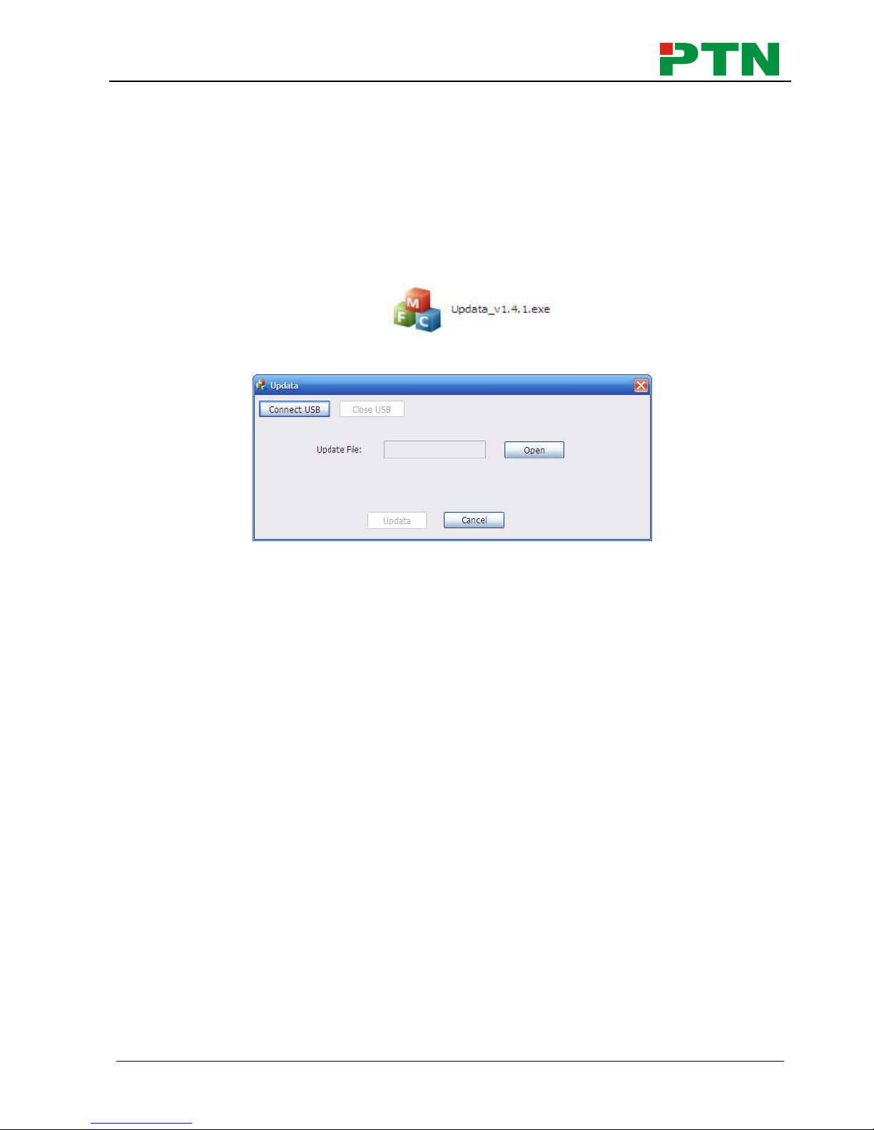
5. Firmware Upgrade
The switcher boasts a USB port for online firmware upgrade on the front panel. Follow
these steps to upgrade firmware:
Step1. Copy the upgrade software and the latest upgrade file (.bin) to PC.
Step2. Connect the USB ports of the switcher and the PC via USB cable.
Step3. Double-click the update software icon (see as below).
It will enter the upgrade interface shown as below:
Step4. Click Connect USB.
Step5. Click Open to load the upgrade file, then click Updata to start firmware
upgrading.
Note:
1. To ensure available control, the COM number of the PC should be 1~9.
2. If the update progress bar can’t go on, please cut off power, and then restart this
machine to update firmware again.
Page 37

Single Plug-in Card Matrix Switcher
PTN Electronics Limited 32 www.PTN-Electronics.com
6. Specification
6.1 Main Unit
Connectors
Control
1 IR EYE,
1 RS232, 1 TCP/IP
Card Slot
12 PCI-E
Control
Connectors
1 3.5mm mini jack, 1 3-pin pluggable terminal block, 1 RJ45
General
Standards
HDMI 1.4 & HDCP1.3
Resolution
1080p (max)
Power
Supply
100~240V AC
Power
Consumption
181.5w
Temperature
0~50℃
Reference
Humility
10%~90%
Dimension
(W*H*D)
483x 88x 380mm
Weight
5.2 kg
6.2 Signal Cards
6.2.1 FMX-ITP& FMX-OTP
FMX-ITP
FMX-OTP
Input
1 HDBT, 1 Audio
Output
1 HDBT, 1 Audio
Input
Connector
1 Female RJ45
1 3-pin pluggable
terminal block
Output
Connector
1 Female RJ45
1 3-pin pluggable
terminal block
Power
Consumption
13.5w
Power
Consumption
14w
General
Transmission
Distance
(1080p)≤70m
Switching
Speed
﹤100ns
Working
Temperature
0~50℃
Reference
Humility
10%~90%
Standard
HDMI1.3, DVI1.0 & HDCP1.3
Audio
PCM
EDID
Supports EDID Management
Output
Resolution
Auto, 800x600, 1024x768, 720p, 1280x1024, 1080i, 1080p,
1920x1200
Page 38

Single Plug-in Card Matrix Switcher
PTN Electronics Limited 33 www.PTN-Electronics.com
6.2.2 FMX-ISD& FMX-OSD
Input
Output
Input
1 SDI
Output
1 SDI
2 SDI LOOP
Connector
Female BNC
Output
Connector
Female BNC
Output
1 SDI LOOP
Output
Connector
Female BNC
General
Signal
3G-SDI/HD-SDI/SDI
Resolution
1080p (max)
Transmission
Distance
(1080p)≤160m
Data Type
8 & 10 & 12bit
Working
Temperature
0~50℃
Reference
Humility
10%~90%
Power
Consumption
6.1w
6.2.3 FMX-IVG& FMX-OVG
FMX-IVG
FMX-OVG
Input
1 VGA, 1 Audio
Output
1 VGA, 1 Audio
Input
Connector
Female 15 pin HD
1 3-pin pluggable
terminal block
Output
Connector
Female 15 pin HD
1 3-pin pluggable
terminal block
Power
Consumption
4.6w
Power
Consumption
4w
General
Video Signal
VGA, CVBS, YPbPr
Switching
Speed
﹤100ns
Output
Resolution
VGA: 800x600, 1024x768, 720p, 1280x1024, 1080i, 1080p,
1920x1200
YPbPr: 720p, 1080i, 1080p
CVBS: 480i, 576i
Working
Temperature
0~50℃
Reference
Humility
10%~90%
6.2.4 FMX-IDV& FMX-ODV
FMX-IDV
FMX-ODV
Input
1 DVI, 1 Audio
Output
1 DVI, 1 Audio
Input
Connector
Female DB24+5/ HDMI
1 3-pin pluggable
Output
Connector
Female DB24+5/ HDMI
1 3-pin pluggable
Page 39

Single Plug-in Card Matrix Switcher
PTN Electronics Limited 34 www.PTN-Electronics.com
terminal block
terminal block
Power
Consumption
4.5w
Power
Consumption
3.5w
General
Working
Temperature
0~50℃
Reference
Humility
10%~90%
Switching
Speed
﹤100ns
Standard
HDMI1.3 & HDCP
EDID
Supports EDID Management
Output
Resolution
Auto, 800x600, 1024x768, 720p, 1280x1024, 1080i, 1080p,
1920x1200
6.2.5 FMX-IHD& FMX-OHD
FMX-IHD
FMX-OHD
Input
1 HDMI, 1 Analog audio
Output
1 HDMI, 1 Analog audio
Input
Connector
19-pin Type A Female
HDMI
3-pin pluggable
terminal block
Output
Connector
19-pin Type A Female
HDMI
3-pin pluggable
terminal block
Power
Consumption
5w
Power
Consumption
2.7w
General
Audio
PCM
Bandwidth
6.75 Gbps
Switching
Speed
﹤100ns
Standard
HDMI1.3 & HDCP1.3
Working
Temperature
0~50℃
Reference
Humility
10%~90%
EDID
Supports EDID Management
Output
Resolution
Auto, 800x600, 1024x768, 720p, 1280x1024, 1080i, 1080p,
1920x1200
Page 40

Single Plug-in Card Matrix Switcher
PTN Electronics Limited 35 www.PTN-Electronics.com
7. Panel Drawing
CLEAR
ALL
MENU
1 2
3 4
5
6
ENTER
FIRMWAR E
EDID
INPUT S
OUTPU TS
987 0
437.00 mm
23.10 mm
8
8
.
0
0
m
m
7
6
.
8
9
m
m
INPUT
SDI
LOOP
1 2
3 4
5
7 1211
RS232
Tx
Rx
TCP/IP
VGA
INPUT
AUDIO
L
R
DVI
INPUT
AUDIO
L
R
Tx
Rx
L
R
RS232 A UDIO
HDBaseT
INPUT
Seamless
HDMI
INPUT
AUDIO
L
R
DVI
OUTPUT
AUDIO
L
R
VGA
OUTPUT
AUDIO
L
R
Tx
Rx
L
R
RS232 A UDIO
HDBaseT
OUTPUT
Seamless
8 9 10
HDMI
OUTPUT
AUDIO
L
R
VGA
OUTPUT
AUDIO
L
R
HDMI
OUTPUT
AUDIO
L
R
VGA
INPUT
AUDIO
L
R
Page 41

Single Plug-in Card Matrix Switcher
PTN Electronics Limited 36 www.PTN-Electronics.com
8. Troubleshooting & Maintenance
Problems
Causes
Solutions
Color losing or no video
signal output in HDMI
display
The connecting cables may
not be connected correctly
or it may be broken.
Check whether the cables
are connected correctly
and in working condition.
No HDMI signal output in
display while local input is
working normally
Loose cable connection
Reconnect the devices and
make sure they’re well
contacted.
The display doesn’t
support the resolution
Set output resolution to
other supportive ones or
Auto.
Splash screen in output
devices
Poor quality of the
connecting cable
Change for another cable
of good quality.
Poor contact at the input/
output end
Reconnect the devices and
make sure they’re well
contacted.
Cannot control the device
via front panel buttons
Front panel buttons are
locked
Send “/%Unlock;” to
unlock.
Cannot control FMX12 by
control device (e.g. a PC)
through RS232 port
Wrong RS232
communication parameters
Make sure the RS232
communication parameters
are correct.
FMX12 is broken
Send it to authorized
dealer for repairing.
Static becomes stronger
when connecting the video
connectors
Bad grounding
Check the grounding and
make sure it is connected
well.
If your problem persists after following the above troubleshooting steps, seek further
help from authorized dealer or our technical support.
Page 42

Single Plug-in Card Matrix Switcher
PTN Electronics Limited 37 www.PTN-Electronics.com
9. After-sales Service
If there appear some problems when running the device, please check and deal with the
problems reference to this user manual.
1) Product Limited Warranty: PTN warrants that its products will be free from defects
in materials and workmanship for three years, which starts from the first day the
product leaves warehouse (check the SN mark on the product).
Proof of purchase in the form of a bill of sale or receipted invoice must be presented
to obtain warranty service.
2) What the warranty does not cover:
Warranty expiration.
Factory applied serial number has been altered or removed from the product.
Damage, deterioration or malfunction caused by:
Normal wear and tear
Use of supplies or parts not meeting our specifications
No certificate or invoice as the proof of warranty.
The product model showed on the warranty card does not match with the
model of the product for repairing or had been altered.
Damage caused by force majeure.
Servicing not authorized by PTN
Other causes which does not relate to a product defect
Delivery, installation or labor charges for installation or setup of the product
3) Technical Support: Email to our after-sales department or make a call, please
inform us the following information about your cases.
Product version and name.
Detailed failure situations.
The formation of the cases.
Remarks: For any questions or problems, please try to get help from your local
distributor, or email PTN at: support@PTN-electronics.com
Page 43

Page 44

www.PTN-Electronics.com
PTN Electronics Limited
Tel: +86-755-2846 1819
Fax: +86-755-8471 7796
Email: info@PTN-electronics.com
Website: www.PTN-electronics.com
 Loading...