

Page 1
Zertifiziert nach ISO 9001:2008
MONTAGEANLEITUNG
ASSEMBLY GUIDE
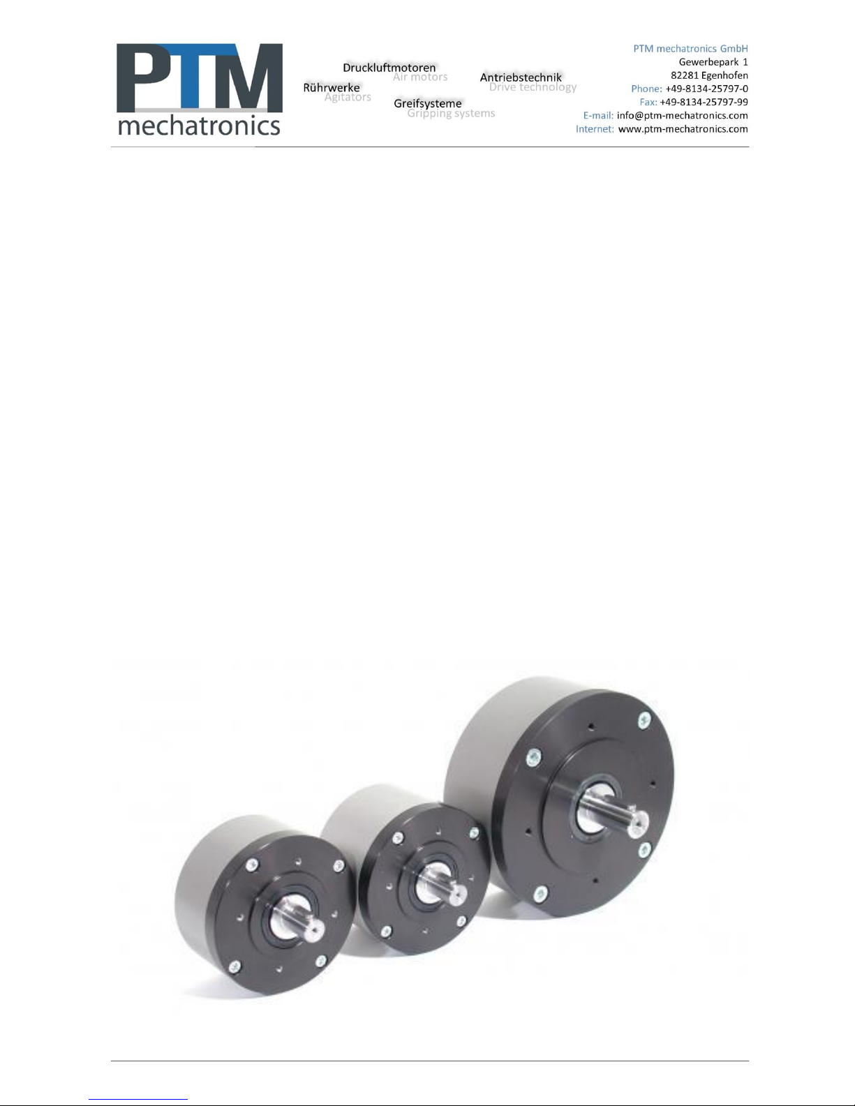
PTM Druckluftmotor
PTM air motor
PMO450 PMO900
PMO1450 PMO1800
PMO3600 PMO7200
Page 2

Montageanleitung / Assembly guide
Seite 2 von 36
Inhalt
A. EINBAUERKLÄRUNG ................................................................................................................................................................ 3
A.1 Funktionsbeschreibung .......................................................................................................................................................... 3
A.2 Hersteller und Kundendienst .................................................................................................................................................. 3
A.3 Wichtige Hinweise .................................................................................................................................................................. 4
A.4 Varianten ............................................................................................................................................................................... 6
A.5 Allgemeine Sicherheitshinweise ............................................................................................................................................. 8
B. INBETRIEBNAHME .................................................................................................................................................................... 9
B.1 Druckluftanschluss ................................................................................................................................................................. 9
B.2 Reparaturen ........................................................................................................................................................................... 9
C. EX-SCHUTZ ............................................................................................................................................................................. 10
C.1 Allgemeine Sicherheitshinweise ........................................................................................................................................... 10
C.2 Motorvarianten ..................................................................................................................................................................... 10
C.3 Prüfen des Ex-Schutzes ....................................................................................................................................................... 10
C.4 Bedienung ............................................................................................................................................................................ 11
C.5 Grundlagen .......................................................................................................................................................................... 11
C.5.1 Europäische Richtlinien, Gesetze und Vorschriften .................................................................................................................. 11
C.5.2 Kennzeichen nach Richtlinie 94/9/EG und 2014/34/EU ................................................................................................ ............ 11
C.6 Vorschriften zum Explosionsschutz ...................................................................................................................................... 11
C.6.1 Zoneneinteilung für explosionsgefährdete Bereiche ................................................................................................................. 11
C.7 Inbetriebnahme, Installation ................................................................................................................................................. 12
C.7.1 Verwendung, Einsatzbedingungen.......................................................................................................................................... 12
C.7.2 Umgebungstemperaturen ........................................................................................................................................................ 13
C.7.3 Maximale Oberflächentemperatur ............................................................................................................................................ 13
C.7.4 Temperaturbeständigkeit ......................................................................................................................................................... 13
C.7.5 Instandhaltung, Wartung .......................................................................................................................................................... 13
C.7.6 Störungsbeseitigung ................................................................................................................................................................ 13
C.7.7 Entsorgung .............................................................................................................................................................................. 13
D. ANHANG ................................................................................................................................ ................................ ........................... 14
D.1 EG – Einbauerklärung ................................................................................................................................................................ 14
D.2 EG – Konformitätserklärung ........................................................................................................................................................ 15
D.3 EG – Konformitätsbescheinigung ................................................................................................................................................ 16
A. INSTALLATION CERTIFICATE ................................................................................................................................................ 20
A.1 Functional description .................................................................................................................................................................... 20
A.2 Manufacturer and customer service................................................................................................................................................ 20
A.3 Important notes .............................................................................................................................................................................. 21
A.4 Versions ......................................................................................................................................................................................... 23
A.5 General safety precautions ............................................................................................................................................................. 25
B. COMMISSIONING .................................................................................................................................................................... 26
B.1 Compressed air connection ............................................................................................................................................................ 26
B.2 Repairs .......................................................................................................................................................................................... 26
C. EX PROTECTION..................................................................................................................................................................... 27
C.1 General safety precautions ............................................................................................................................................................ 27
C.2 Motor versions ............................................................................................................................................................................... 27
C.3 Verification of Ex-protection ........................................................................................................................................................... 27
C.4 Operation ....................................................................................................................................................................................... 28
C.5 Principles ....................................................................................................................................................................................... 28
C.5.1 European directives, laws and provisions ..................................................................................................................................... 28
C.5.2 Marking in accordance with Directive 94/9/EG and 2014/34/EU ................................................................................................... 28
C.6 Explosion protection regulations ..................................................................................................................................................... 28
C.6.1 Zone classification of potentially explosive areas ......................................................................................................................... 28
C.7 Commissioning, installation ............................................................................................................................................................ 29
C.7.1 Use, application conditions ........................................................................................................................................................... 29
C.7.2 Ambient temperatures ................................................................................................................................................................ .. 30
C.7.3 Maximum surface temperature ..................................................................................................................................................... 30
C.7.4 Temperature resistance ............................................................................................................................................................... 30
C.7.5 Maintenance, repair ..................................................................................................................................................................... 30
C.7.6 Troubleshooting ........................................................................................................................................................................... 30
C.7.8 Disposal ....................................................................................................................................................................................... 30
D. APPENDIX ........................................................................................................................................................................................ 31
D.1 Declaration of conformity................................................................................................................................................................ 31
D.2 Declaration of Conformity ............................................................................................................................................................... 32
D.3 EG Certification of Conformity ................................................................................................ ........................................................ 33
Page 3

Montageanleitung / Assembly guide
Seite 3 von 36
A. EINBAUERKLÄRUNG
Unsere Produkte werden grundsätzlich nach geltenden Vorschriften und Normen entwickelt und hergestellt.
Sie basieren auf heutigem Wissen und unterliegen Änderungen sowie Verbesserungen. Eventuelle
Ergänzungen oder Änderung der EU-Richtlinien werden hierbei berücksichtigt. Die Originaleinbauerklärung
im Sinne der Richtlinie 2006/42/EG für Maschinen, Anhang II Teil 1 Abschnitt B, liegt diesem Produkt bei.
Druckluftmotoren sind nichtelektrische Betriebsmittel im Sinne unvollständiger Maschinen.
Die Geräte sind nur für eine sachgerechte und bestimmungsgemäße Verwendung zugelassen. Bei
Zuwiderhandlungen erlischt jegliche Garantie und Herstellerverantwortung!
Vor Inbetriebnahme sind die jeweiligen länderspezifischen Vorschriften zu beachten.
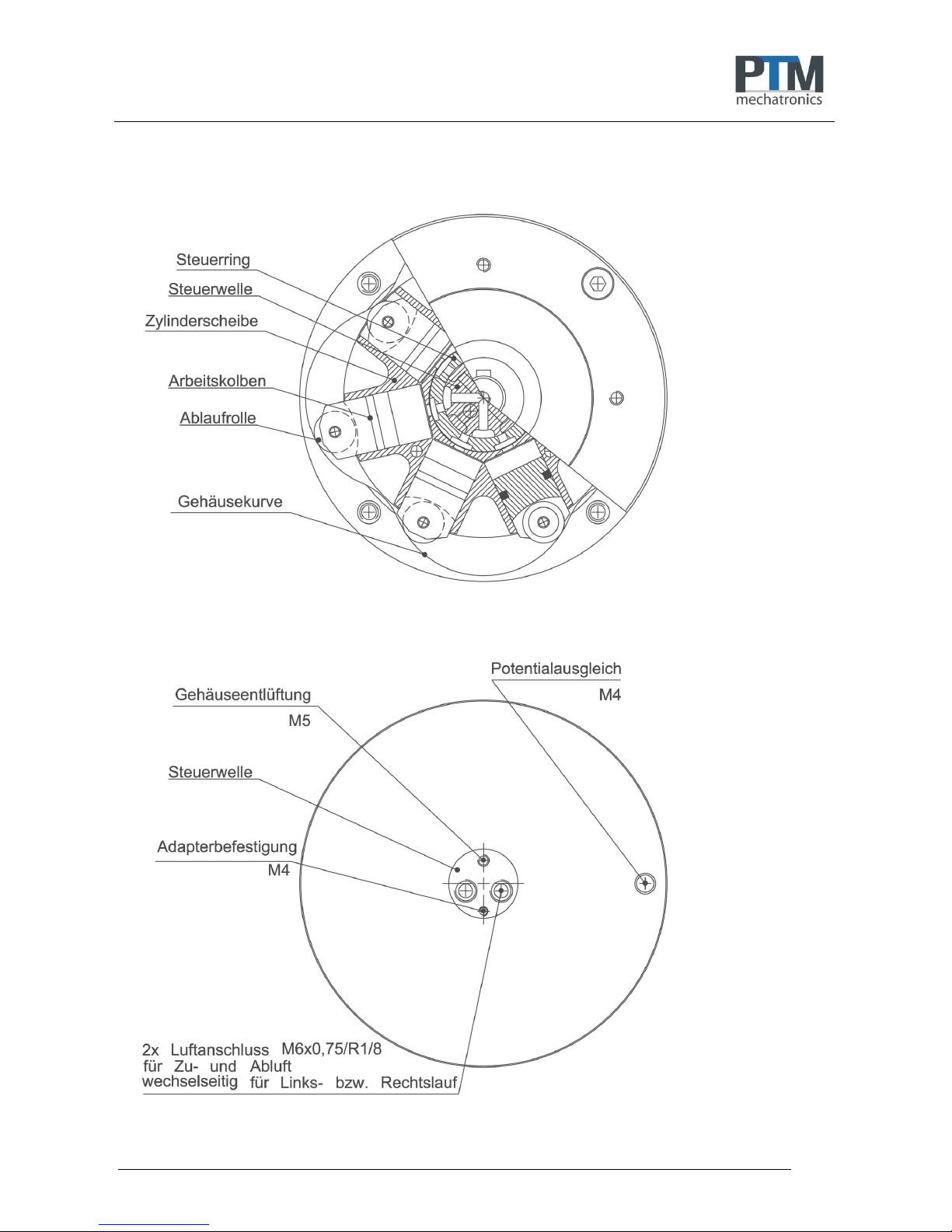
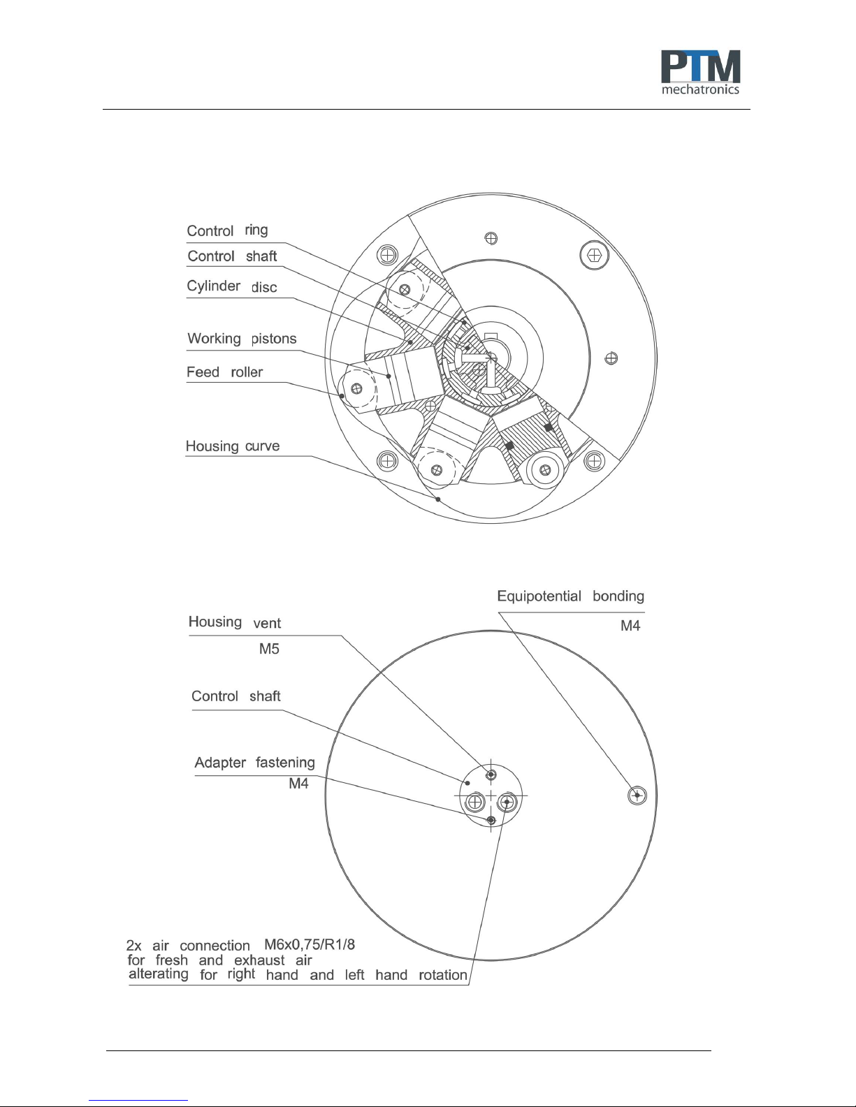
A.1 Funktionsbeschreibung
Der Druckluftmotor (Radialkolbenmotor) besitzt weder Pleuel noch Kurbelwelle. Die sternförmig
angeordneten Arbeitskolben rollen auf der im Gehäuseinneren eingearbeiteten Kurve ab. Die zum Antrieb
notwendige Druckluft gelangt über einen mitlaufenden Steuerring der Zylinderscheibe und eine im Zentrum
feststehende Steuerwelle zu den Arbeitskolben. Zuluft und Abluft versorgen bzw. entlüften abwechselnd die
Kolben. Durch Umkehr der Zu- und Abluft kann sofortiger Rechts- bzw. Linkslauf bei Motoren ohne Getriebe
erzeugt werden. Von den sieben installierten Kolben sind immer drei bis vier an der Erzeugung des
Drehmomentes beteiligt. Die Kolben am höchsten Kurvenpunkt werden entlüftet und zwangsweise an ihren
Ausgangspunkt zurückgeführt. Der Arbeitsablauf entspricht dem eines einfach wirkenden Zylinders. Zur
Ableitung des entstehenden leichten Überdrucks (Volumen max: 0,1m3/h) während des Betriebs aus dem
Geräteinneren ist eine Abluftöffnung vorgesehen. Die Ablaufrollen sind aus hochbelastbarem
Kunststoffmaterial gefertigt und zweifach mit Kugellagern gelagert. Dadurch entsteht fast keine Reibung,
sondern nur ein minimales Abwälzgeräusch. Im Gegensatz zu herkömmlichen Lamellenmotoren entwickelt
der PMO sein höchstes Drehmoment im niedrigen Drehzahlbereich bei sehr geringem Luftverbrauch. Er darf
nur zwischen 30 < n< 300 min-1. eingesetzt werden. Als Medium wird aufbereitete, nicht geölte Druckluft mit
2-6 bar und einem Filterungsgrad <=5µ verwendet.
A.2 Hersteller und Kundendienst
PTM mechatronics GmbH
Gewerbepark 1
D-82281 Egenhofen
Deutschland
Tel.: +49 8134 - 25797 - 0
Fax: +49 8134 - 25797 - 99
E-Mail: info@ptm-mechatronics.com
Internet: www.ptm-mechatronics.com
Beim Kundendienst bitte immer die Gerätenummer angeben.
Bitte kontaktieren Sie unseren Kundenservice vor dem Versand von Reparaturgeräten oder Rücklieferungen,
andernfalls müssen wir die Annahme der Sendung verweigern.
© PTM mechatronics GmbH
Stand 03/2017
Änderungen vorbehalten
Page 4
Montageanleitung / Assembly guide
Seite 4 von 36
A.3 Wichtige Hinweise
Druckluft
Als Medium darf nur aufbereitete, nicht geölte Druckluft mit 2-6 bar und einem
Filterungsgrad <=5µ verwendet werden.
Drehzahl
Der Motor darf nur zwischen 30 < n< 300 min
-1.
eingesetzt werden.
Zum Schutz vor zu hoher Drehzahl bieten wir Durchflussreduzierungen an.
Bei Nutzung eines Getriebes ist der Enddrehzahlbereich
3:1 10 < n< 100 min-1
9:1 3,3 < n< 33 min-1
1:2 60 < n< 600 min-1
Rührwerk Dauerbetrieb
Im Dauerbetrieb in einer Drehrichtung ist die Abluftleitung größer als die
Zuluftleitung auszulegen.
Bei Nutzung eines Schalldämpfers in der Abluft dürfen nur
Hochleistungsschalldämpfer verwendet werden.
Es darf kein Staudruck im Motor entstehen.
Gehäuseentlüftung
Das Gehäuse muss im Betrieb entlüften können. Die Gehäuseentlüftung darf
deshalb nicht verschlossen werden.
Page 5
Montageanleitung / Assembly guide
Seite 5 von 36
Page 6

Montageanleitung / Assembly guide
Seite 6 von 36
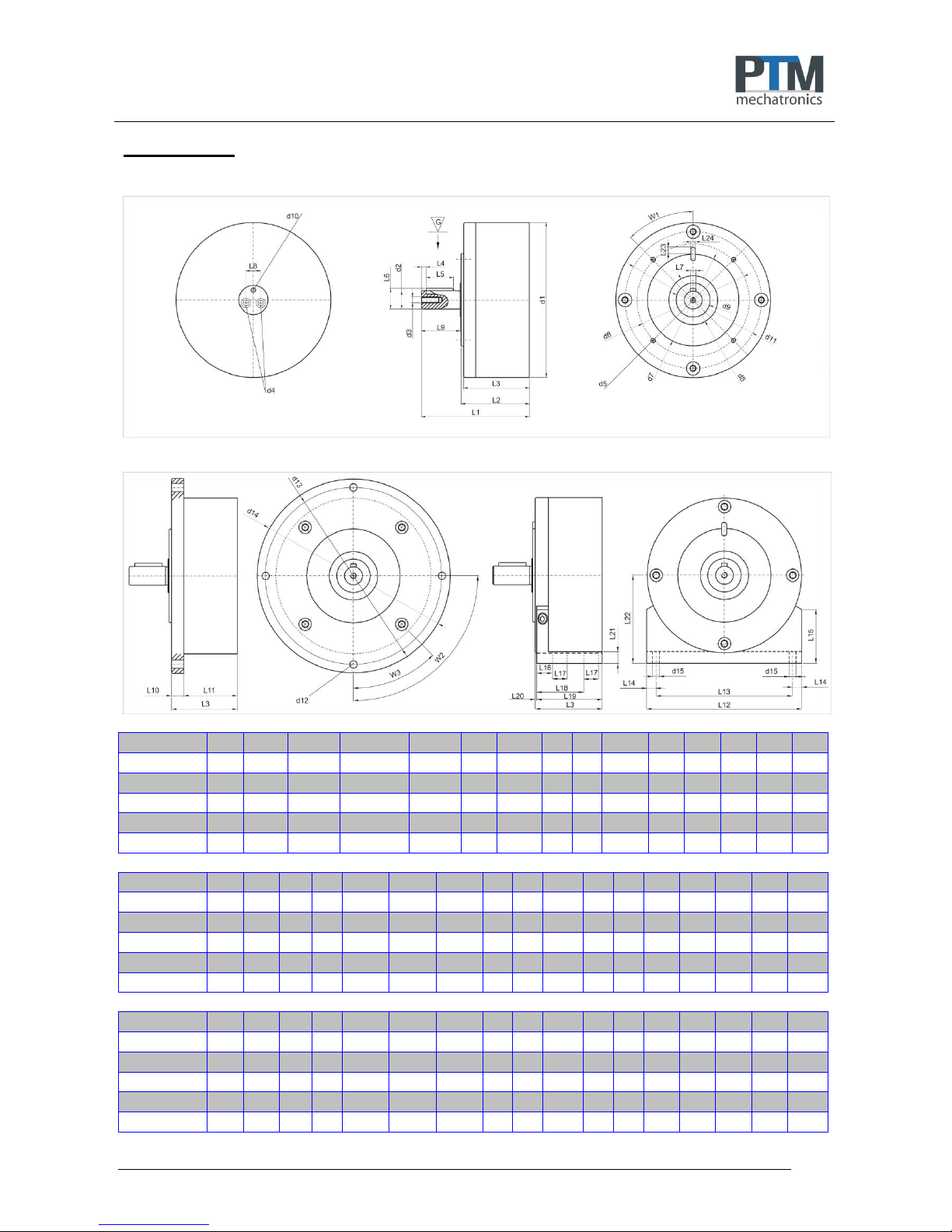
A.4 Varianten
Abmessungen:
mit Montageflansch: mit Montagewinkel:
d 1
d 2
d 3
d 4
d 5
d 6
d 7
d 8
d 9
d 10
d 11
d 12
d 13
d 14
d 15
PMO 0450
99
14 h6
M 4x12
M 6x0,75x8
M 4x9
67
55 h6
40
28
M 5x5
87
5,4
110
120
5
PMO 0900
99
14 h6
M 4x12
M 6x0,75x8
M 4x9
67
55 h6
40
28
M 5x5
87
5,4
110
120
5
PMO 1800
159
19 h6
M 6x18
R1/8x9
M 6x10
115
95 h6
50
35
M 5x5
140
8,5
180
199
7
PMO 3600
159
19 h6
M 6x18
R1/8x9
M 6x10
115
95 h6
50
35
M 5x5
140
8,5
180
199
7
PMO 7200
159
19 h6
M 6x18
R1/8x9
M 6x10
115
95 h6
50
35
M 5x5
140
8,5
180
199
7
L 1
L 2
L 3
L 4
L 1 VA
L 2 VA
L 3 VA
L 5
L 6
L 7
L 8
L 9
L 10
L 11
L 12
L 13
L 14
PMO 0450
78
52
51 3 81
55
53,5
18
16
5 N9
11
25
12
39
99
89 5 PMO 0900
93
67
65 3 95,5
69,5
68
18
16
5 N9
11
25
12
54
99
89
5
PMO 1800
111
70
68 5 115
74
71,5
28
22
6 N9
15
40
13
55
159
140
9,5
PMO 3600
133
92
90 5 137
96
93,5
28
22
6 N9
15
40
13
77
159
140
9,5
PMO 7200
194
153
151
5
198
157
154,5
28
22
6 N9
15
40
13
138
159
140
9,5
L 15
L 16
L 17
L 18
L 19
L 20
L 21
L 22
L 23
L 24
W 1
W 2
W 3
PMO 0450
40
15
10
37
50
0,5
10
58 6 4 N9
45°
90°
45°
PMO 0900
40
15
10
37
50
0,5
10
58 6 4 N9
45°
90°
45°
PMO 1800
55
16
15
48
67
0,5
12
90 7 5 N9
45°
90°
45°
PMO 3600
55
16
15
48
67
0,5
12
90 7 5 N9
45°
90°
45°
PMO 7200
55
16
15
48
67
0,5
12
90
7
5 N9
45°
90°
45°
Page 7

Montageanleitung / Assembly guide
Seite 7 von 36
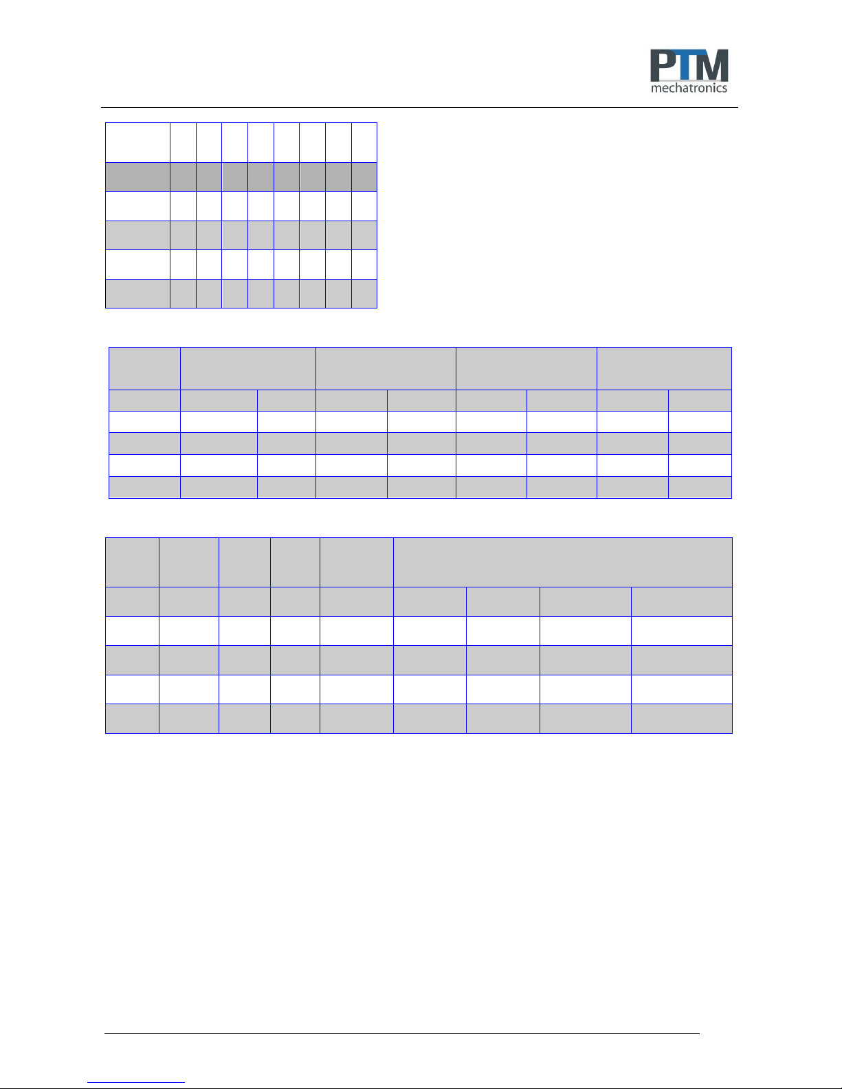
Abmessung
mit Getriebe
L 1
3:1
L 2
3:1
L 3
3:1
L 11
3:1
L 1
9:1
L 2
9:1
L 3
9:1
L 11
9:1
PMO 0450
120
94
93
81
104
78
77
65
PMO 0900
135
109
107
96
119
93
91
80
PMO 1800
161
120
118
105
137
96
94
81
PMO 3600
183
142
140
127
159
118
116
103
PMO 7200
244
203
201
188
220
179
177
164
Ohne Getriebe
n min n max
= 30 U/min = 300 U/min
Untersetzung 3 : 1
n min n max
= 10 U/min = 100 U/min
Untersetzung 9:1
n min n max
= 3,3 U/min = 33 U/min
Übersetzung 1:2
n min n max
= 60 U/min = 600 U/min
PMO 0450
4 Nm
2 Nm
12 Nm
6 Nm
36 Nm
18 Nm
2 Nm
1 Nm
PMO 0900
8 Nm
3 Nm
24 Nm
9 Nm
72 Nm
27 Nm
4 Nm
1,5 NM
PMO 1800
16 Nm
2 Nm
48 Nm
6 Nm
144 Nm
18 Nm
8 Nm
1 Nm
PMO 3600
32 Nm
3 Nm
96 Nm
9 Nm
288 Nm
27 Nm
16 Nm
1,5 Nm
PMO 7200
64 Nm
6 Nm
194 Nm
19 Nm
576 Nm
54 Nm
32 Nm
3 Nm
max.
allowed
axial loading
radial
dyn. C
radial
stat. Co
max.
allowed
radial loading
weights
without with with with
gear 3:1 gear 9:1 gear 1:2 gear
PMO 0450
100 N
750 N
400 N
5 Nm
1,10 Kg
2,00 Kg
2,80 Kg
2,10 Kg
PMO 0900
100 N
750 N
400 N
5 Nm
1,30 Kg
2,20 Kg
3,00 Kg
2,30 Kg
PMO 1800
200 N
1500 N
800 N
10 Nm
3,40 Kg
6,10 Kg
7,90 Kg
5,90 Kg
PMO 3600
200 N
1500 N
800 N
10 Nm
4,00 Kg
6,70 Kg
8,50 Kg
6,50 Kg
PMO 7200
200 N
1500 N
800 N
10 Nm
6,40 Kg
9,10 Kg
10,90 Kg
8,90 Kg
Page 8

Montageanleitung / Assembly guide
Seite 8 von 36
A.5 Allgemeine Sicherheitshinweise
Die Montageanleitung ist vor Inbetriebnahme vom Bediener des Motors zu lesen und die Hinweise sind
während des Betriebs einzuhalten.
1. Die bestimmungsgerechte Gebrauchslage des Motors ist beliebig.
2. Prüfen Sie, ob alle Verpackungs- und Verschmutzungsschutzreste entfernt sind.
3. Beachten Sie, dass alle Anschlüsse und Verbindungen richtig befestigt sind.
4. Die Sicherheitssiegel dürfen nicht beschädigt werden.
5. Instandsetzung nur durch den Hersteller.
6. RL 1999/92/EG beachten (Gesundheitsschutz und Sicherheit der Arbeitnehmer)
7. Max. Betriebsdruck von 6 bar nicht überschreiten.
8. Mindestbetriebsdruck ist 2 bar
9. Die max. Motordrehzahl von 300U/min nicht überschreiten. Gefahr der totalen Zerstörung.
10. Getriebemotoren dürfen erst reversiert werden, wenn sich der Motor im Stillstand befindet.
11. Nicht geölte, getrocknete Druckluft mit Filterungsgrad <= 5µ verwenden.
12. Temperatureinsatzbereich ist -10°C bis +80°C
13. Prüfen Sie die Lieferung mit Hilfe Ihrer Bestellung und des Lieferscheines mit Seriennummer auf
Authentizität und Vollständigkeit.
Die Unfallverhütungsvorschriften und eventuell zusätzliche Sicherheitsvorschriften des jeweiligen Landes
sind unbedingt einzuhalten.
Page 9
Montageanleitung / Assembly guide
Seite 9 von 36
B. INBETRIEBNAHME
B.1 Druckluftanschluss
Die Funktion und Lebensdauer hängt weitgehend von der Beschaffenheit und dem Druck der zugeführten
Druckluft ab. Überhöhte Feuchtigkeit oder Schmutzpartikel zerstören den Motor. Ein hoher Kondensatanteil in
der Druckluft verursacht Rostansatz im Motor und der Schalldämpfer vereist bei der Luftexpansion.
Bei der Inbetriebnahme des Druckluftmotors folgende Punkte zu beachten:
Verwenden Sie für die Zu- und Abluft des Motors den richtigen Luftschlauch (siehe Tabelle)
PMO450 PMO900
PMO1450 PMO1800 PMO3600
Zuluft Durchmesser 6mm
Zuluft Durchmesser 8mm
Abluft Durchmesser 8mm
(bei Dauerbetrieb in eine Drehrichtung)
Abluft Durchmesser 10mm
(bei Dauerbetrieb in eine Drehrichtung)
Reduzieren Sie erst unmittelbar vor den Druckluftanschlüssen des Motors auf den notwendigen,
kleineren Durchmesser. Hierfür stehen diverse Adapterversionen als Zubehör zur Verfügung.
Die Entlüftungsbohrung M5 für den im Innenraum des Druckluftmotors entstehenden Überdruck darf
unter keinen Umständen verschlossen werden. Entlüftungsschlauch mit lichtem Durchmesser 3mm
verwenden.
Luft-Hauptleitungen benötigen ein leichtes Gefälle von mindestens 1% in Strömungsrichtung, damit
Kondenswasser an der tiefsten Stelle durch ein Ventil (manuell oder automatisch) abgelassen werden
kann.
Schließen Sie Abzweigungen bei horizontaler Hauptleitung nach oben - und bei vertikaler Hauptleitung
nicht an der tiefsten Stelle - an. Dadurch wird verhindert, dass in der Hauptleitung stehendes
Kondenswasser in den Abzweig fließt.
Benutzen Sie Wartungseinheiten mit einem Luftfilter von mindestens < 5µ Filterungsgrad. Installieren Sie
die Wartungseinheit mit mindestens G 1/4 Luftanschluss in unmittelbarer Nähe des Motors.
Bei Einsatz unter Wasser muss unbedingt auf korrekt vorgetrocknete, gekühlte Druckluft geachtet
werden um die Bildung von Kondensat zu vermeiden.
Der Luftfilter bedarf einer regelmäßigen Wartung, wobei das gespeicherte Kondenswasser abgelassen
und der Filter gereinigt werden muss.
Der Druckluftmotor erzielt bei 6 bar (85 psi) seine optimale Leistung. Beträgt der Druck im Druckluftnetz
mehr als 6 bar, dann müssen Sie einen Druckregler einsetzen.
Die benötigte Umdrehungszahl kann über den Druckregler bzw. eine Zuluftdrossel eingestellt werden.
Ein Überdrehen von über 300U/min und damit Zerstören des Motors muss sowohl ohne Last als auch
unter Last unbedingt verhindert werden.
B.2 Reparaturen
Bringt der Druckluftmotor nicht die erforderliche Leistung, so überprüfen Sie folgende Punkte:
a) Ist der Luftdruck ausreichend (6 bar / 85 psi)?
b) Ist der Luftdruck konstant oder schwankend?
c) Steht die notwenige Luftmenge zur Verfügung?
d) Ist der Luftfilter an der Wartungseinheit sauber?
e) Sind Leckverluste zwischen Wartungseinheit und Druckluftmotor vorhanden?
f) Liegen Querschnittsverengungen in der Abluftleitung vor?
Liegt keiner der genannten Fehler vor, dann muss der Motor zur Überprüfung zum Hersteller.
Reparaturen bitte nur beim Hersteller ausführen lassen. Die Versiegelung darf nicht beschädigt sein.
Page 10

Montageanleitung / Assembly guide
Seite 10 von 36
C. EX-SCHUTZ
für den Einsatz in explosionsgefährdeten Bereichen.
C.1 Allgemeine Sicherheitshinweise
Die Montageanleitung ist vor Inbetriebnahme vom Bediener des Motors zu lesen und die Hinweise sind
während des Betriebs einzuhalten.
Motor nur in explosionsgeschützten Anlagen betreiben.
Potentialausgleich herstellen. (Auf der Rückseite des Motors mit Linsenkopfschraube M4)
Nur leitfähige Druckschläuche verwenden.
Als Medium wird außerhalb des Ex-Bereiches erzeugte und aufbereitete Druckluft verwendet.
Gehäuseentlüftung über Anschluss M5 außerhalb des explosionsgefährdeten Bereiches entlüften.
Die Unfallverhütungsvorschriften und eventuell zusätzliche Sicherheitsvorschriften des jeweiligen Landes
sind unbedingt einzuhalten.
C.2 Motorvarianten
Druckluftmotoren sind nichtelektrische Betriebsmittel und unterliegen beim Einsatz in Zone 1 und 21 keiner
Zulassungspflicht.
Die Druckluftmotoren sind in verschiedenen Ausführungen und Ausbaustufen erhältlich.
Anwendung finden diese Motoren zum Beispiel in Lackierereien (lösungsmittelhaltige Farben und Lacke, z. B.
Benzin, Kerosin) und Mühlen bzw. Silos usw.
Die Qualifizierung hinsichtlich der Oberflächentemperatur ist T5; für alle Gase, Dämpfe und Nebel mit einer
Zündtemperatur > 100°C sind die Geräte keine Zündquelle. Im Staub-Ex-Bereich ist 100°C die
Bezugstemperatur für die weiteren Überlegungen hinsichtlich Sicherheitsabstand von der Glimmtemperatur.
Eine Entscheidung darüber kann nur der Betreiber treffen.
Das am Radialkolbenmotor angebaute Getriebe ist ein Planetengetriebe. Es reduziert die Antriebsdrehzahl je
Getriebestufe um ein Drittel und erhöht das max. Drehmoment um den Faktor 3.
ACHTUNG: Drehrichtungswechsel erst nach Stillstand des Motors vornehmen. Siehe A.1/10
Der Radialkolbenmotor PMO mit oder ohne angebautem Getriebe kann folgendermaßen eingesetzt werden:
o In der Zone 1 (Gas-Ex, Kategorie 2G) in den Explosionsgruppe IIA und IIB.
o In der Zone 21 (Staub-Ex, Kategorie 2D) bei nicht-leitfähigen Stäuben mit einer Mindestzündenergie
> 3 mJ
C.3 Prüfen des Ex-Schutzes
Vor der Inbetriebnahme in explosionsgefährdeter Umgebung ist zu prüfen:
1. Druckluftmotor explosionsgeschützt?
2. Anlage explosionsgeschützt?
3. Potentialausgleich hergestellt?
4. Leitfähige Schläuche und Schlauchverbindungen verwendet?
Page 11

Montageanleitung / Assembly guide
Seite 11 von 36
C.4 Bedienung
Beim Einsatz in explosionsgefährdeten Bereichen müssen die Kugellager nach einer Laufzeit von spätestens
45.000 Stunden erneuert werden.
C.5 Grundlagen
Aufgrund des geplanten Einsatzes der Radialkolbenmotoren und Getriebe im explosionsgefährdeten Bereich
ist nachfolgende EU-Richtlinie maßgebend:
C.5.1 Europäische Richtlinien, Gesetze und Vorschriften
94/9/EG und 2014/34/EU: Europäische Explosionsschutzrichtlinie
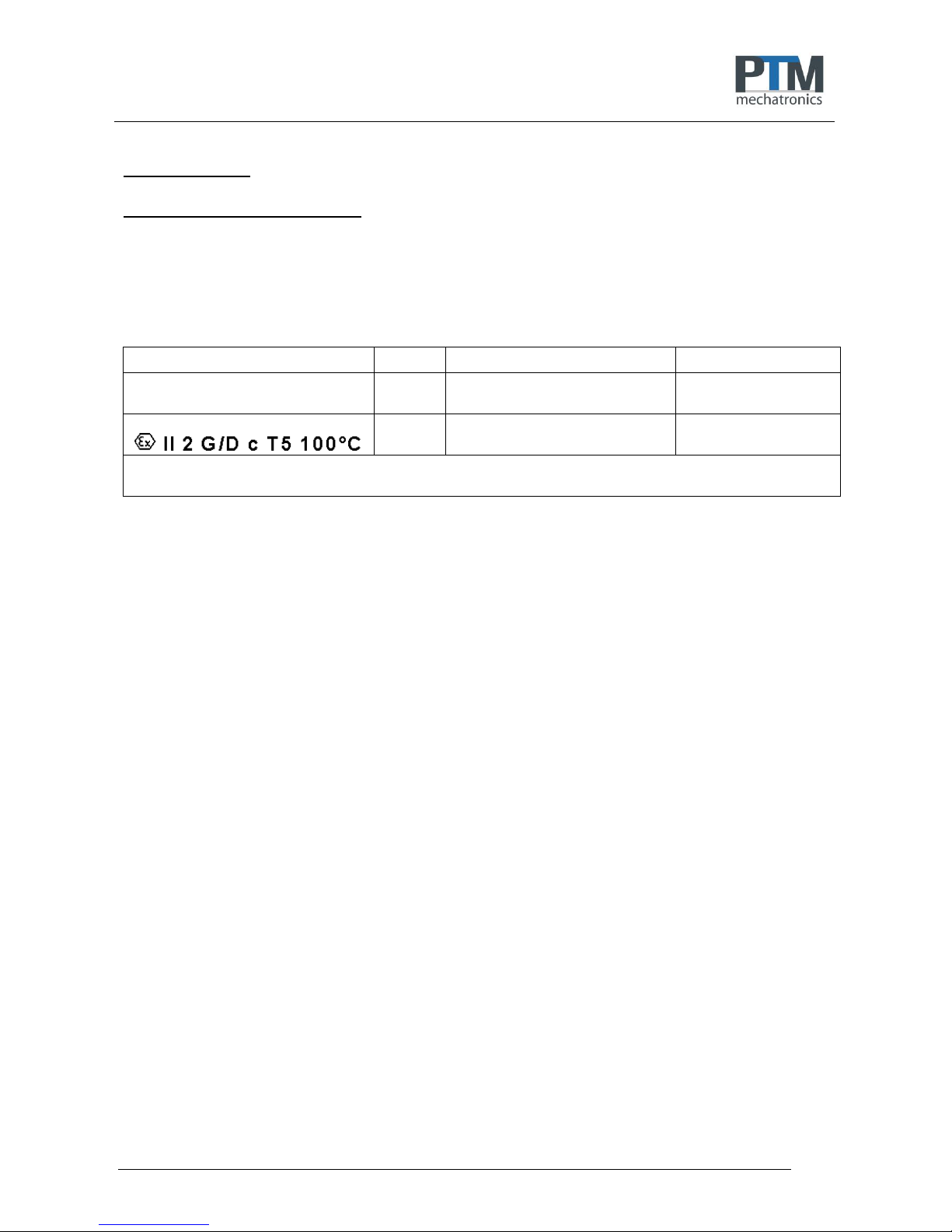
C.5.2 Kennzeichen nach Richtlinie 94/9/EG und 2014/34/EU
Das Kennzeichen des nicht-elektrischen Betriebsmittels lautet:
II 2 G/D c T5 100°C
C.6 Vorschriften zum Explosionsschutz
Für Betriebsmittel in explosionsgefährdeten Bereichen sind vom Betreiber eine Reihe von Vorschriften zu
beachten. Die folgende Auflistung gibt einen Überblick der wesentlichen Vorschriften.
Innerhalb der Europäischen Union gelten:
- >Richtlinie 1999/92/EG über Mindestvorschriften zur Verbesserung des Gesundheitsschutzes und
- der Sicherheit der Arbeitnehmer, die durch explosionsfähige Atmosphären gefährdet werden
- können.
- >EN 50014
- Elektrische Betriebsmittel für explosionsgefährdete Bereiche - Allgemeine Bestimmungen
- >EN 60079-14 (IEC 60079-14)
- Elektrische Betriebsmittel für gasexplosionsgefährdete Bereiche - Teil 14: Elektrische Anlagen in
- explosionsgefährdeten Bereichen
- >EN 60079-10 (IEC 60079-10)
- Elektrische Betriebsmittel für gasexplosionsgefährdete Bereiche - Teil 10: Einteilung der
- explosionsgefährdeten Bereiche
- >DIN EN 1127-1
- Explosionsfähige Atmosphären - Explosionsschutz - Teil 1: Grundlagen und Methodik
- >DIN EN 13463-1
- Nichtelektrische Geräte für den Einsatz in explosionsgefährdeten Bereichen - Teil 1: Grundlagen
- und Anforderungen
- >DIN EN 13463-5
- Nichtelektrische Geräte zum Einsatz in explosionsgefährdeten Bereichen - Teil 5: Schutz durch
- sichere Bauweise
Weiterhin können zusätzliche nationale Vorschriften und Richtlinien gelten.
C.6.1 Zoneneinteilung für explosionsgefährdete Bereiche
Explosionsgefährdete Bereiche sind Bereiche, in denen aufgrund der örtlichen und betrieblichen Verhältnisse
explosionsfähige Atmosphäre in Gefahr drohender Menge auftreten kann. Sie werden in mehrere Zonen
unterteilt.
Page 12

Montageanleitung / Assembly guide
Seite 12 von 36
Für explosionsgefährdete Bereiche durch brennbare Gase, Dämpfe oder Nebel gilt:
a) Zone 0/20 - umfasst Bereiche, in denen gefährliche explosionsfähige Atmosphäre ständig oder
langzeitig vorhanden ist.
b) Zone 1/21 - umfasst die Bereiche, in denen damit zu rechnen ist, dass gefährliche explosionsfähige
Atmosphäre gelegentlich auftritt.
c) Zone 2/22 - umfasst Bereiche, in denen damit zu rechnen ist, dass gefährliche explosionsfähige
Atmosphäre nur selten und dann auch nur kurzzeitig auftritt.
C.7 Inbetriebnahme, Installation
Radialkolbenmotoren und Getriebe besitzen Gehäuse der Schutzart IP 67 bzw. IP 68, welche den
notwendigen IP-Schutz gewährleisten. Unabhängig davon ist in Abhängigkeit der Einsatzbedingungen die
Zeit zur Reinigung des Betriebsmittels von Staubablagerungen durch den Betreiber festzulegen.
Weitere wichtige Fakten:
o Das Gerät darf in der Kategorie 2 (Zone 1 oder 21) durch Fachleute in Betrieb genommen werden.
o Verschlüsse sind nach dem Öffnen und Schließen wieder anzubringen.
o Öffnungen für Zu- und Abluft dürfen nicht verschlossen werden.
o Die Geräte sind nur für den Betrieb mit Druckluft mindestens der Qualitätsklasse 5 nach ISO 8573-1
zugelassen, die außerhalb des Ex-Bereiches erzeugt und aufbereitet wurde. Die Verwendung von
Flüssigkeiten und Gasen gehört nicht zum bestimmungsgemäßen Gebrauch. Anforderungen sind in der
Montageanleitung aufgeführt.
o Bei Entladung elektrostatisch aufgeladener Teile können zündfähige Funken entstehen. Der Betrieb der
Geräte ist mit Schläuchen und Schlauchbündeln bis zu einem maximalen Außendurchmesser von Ø 20
mm zulässig.
o Beim Betrieb der Geräte ist ein wirksamer Potenzialausgleich über die Erdungsschraube am Gehäuse
herzustellen.
o Schlagvorgänge unter Beteiligung von Rost und Leichtmetallen und ihren Legierungen können
zündfähige Funken bilden. Die Verwendung von Werkzeugen mit korrodierten Oberflächen ist untersagt.
Die Geräte sind vor herunterfallenden Gegenständen zu schützen.
o Explosionsfähige Atmosphäre oder explosionsfähige Stäube dürfen nicht in das Gehäuse eindringen.
o Der Betrieb des Gerätes ist nur bei vollständig geschlossenen und unversehrten Gehäusen zulässig.
o Der Betrieb bei beschädigtem Gehäuse ist untersagt.
o Druckluft darf nicht in Bereiche explosionsfähiger Staubatmosphären ausgeblasen werden. Die
Abluftleitungen sind aus dem Ex-Bereich heraus zu führen.
o Bei der Auswahl von Werkstoffen, Materialien und Befestigungszubehör sind Korrosion, Verschleiß und
sonstige Wechselwirkungen zu berücksichtigen.
o Die Anzahl und Auswahl demontierbarer Verbindungen sind auf ein Mindestmaß zu begrenzen,
Schlauchverbindungen sind möglichst kurz zu halten und mechanische Spannungen zu vermeiden.
o Das Betriebsmittel genügt IP 67 bzw. IP 68 an Gehäuse und Seitenteilen. Ein zusätzlicher Schutz gegen
Feuchtigkeit ist nicht notwendig.
C.7.1 Verwendung, Einsatzbedingungen
o Die Geräte sind nur für eine sachgerechte und bestimmungsgemäße Verwendung zugelassen. Bei
Zuwiderhandlungen erlischt jegliche Garantie und Herstellerverantwortung!
o Es dürfen nur solche Zubehörteile in explosionsgefährdeten Bereichen verwendet werden, die alle
Anforderungen der europäischen Richtlinien und der jeweiligen nationalen Gesetzgebung erfüllen.
o Der Radialkolbenmotor zum Antrieb des Getriebes darf bis zu einem maximalen Überdruck von 6 bar
eingesetzt werden. Die maximale Drehzahl des Radialkolbenmotors liegt bei 300 min-1, die
Getriebedrehzahl bei 100 min-1.
o Eine direkte gefährliche elektrostatische Entladung auf die Betriebsmittel ist nicht zulässig. Solche
Entladungen können im Normalfall nicht durch Menschen erzeugt werden, sondern erfordern eine
Druckluftdüse o.ä..
o Der Einsatz im Staub-Ex-Bereich ist bei nicht-leitfähigen Stäuben mit einer Mindestzündenergie > 3 mJ
zulässig.
o Die in der Montageanleitung spezifizierten Umgebungsbedingungen sind unbedingt einzuhalten.
o Blitzschutzmaßnahmen sind durch den Betreiber zu gewährleisten.
Page 13

Montageanleitung / Assembly guide
Seite 13 von 36
C.7.2 Umgebungstemperaturen
Der Umgebungstemperaturbereich wird mit -10°C ≤ Ta ≤ +80°C in Abweichung zum
Standardtemperaturbereich angegeben.
C.7.3 Maximale Oberflächentemperatur
Die Temperaturmessungen am Motor-, Getriebegehäuse und den Steuerwellen wurden bei
Umgebungstemperaturen zwischen 21°C und 24°C durchgeführt. Dabei wurde eine maximale Erwärmung
unter Annahme ungünstigster Betriebsbedingungen (Maximale Belastung: 2 Nm; Drehzahl 300 min-1) von
8,7°C an der Steuerwelle gemessen. Im weiteren Verlauf der 60-stündigen Messung wurden keine
wesentlichen Temperaturänderungen festgestellt.
C.7.4 Temperaturbeständigkeit
Nicht metallische Gehäuseteile müssen gegen Wärme und Kälte beständig sein und zwar so, dass der
Schutzgrad nicht verringert wird. Kunststoffe müssen einen Temperaturindex TI übereinstimmend mit dem
20.000h-Punkt besitzen, der um mindestens 20K höher ist als die lokale maximale Oberflächentemperatur
unter Berücksichtigung der maximalen Umgebungstemperatur. Die verwendeten Kunststoffe haben alle eine
Dauergebrauchstemperatur von mindestens 100°C und entsprechen somit den gestellten Anforderungen.
C.7.5 Instandhaltung, Wartung
o Instandhaltungsmaßnahmen dürfen nur von der PTM mechatronics GmbH oder von der PTM
mechatronics GmbH speziell ausgebildeten Personen durchgeführt werden.
o Der Austausch von Komponenten darf nur mit Original-Ersatzteilen erfolgen, die auch für den Einsatz im
Ex-Bereich freigegeben sind. Das gilt auch für die verwendeten Schmier- und Hilfsstoffe.
o Die Geräte sind im Ex-Bereich regelmäßig zu warten und zu reinigen. Die Intervalle werden vom
Betreiber gem. den Umweltbeanspruchungen vor Ort festgelegt, z.B. bei einer Staubablagerung von ca.
0,5 - 1 mm.
o Nach der Wartung und/oder Instandhaltung sind alle dabei entfernten Barrieren und Hinweise wieder in
der ursprünglichen Lage anzubringen.
o Staubablagerungen in Spalten beweglicher Teile können sich erwärmen. Es ist notwendig, die
Zwischenräume an sich drehenden Teilen regelmäßig zu reinigen.
o Die montierten äußeren Lager sind nach 45.000 Betriebsstunden und außerhalb von explosionsfähigen
Atmosphären zu tauschen.
o Die Radialkolbenmotoren und Getriebe dürfen nur außerhalb von explosionsfähigen Atmosphären
gereinigt werden.
C.7.6 Störungsbeseitigung
An Geräten, die in Verbindung mit explosionsgefährdeten Bereichen betrieben werden, darf keine
Veränderung vorgenommen werden. Reparaturen am Gerät dürfen nur durch den Hersteller ausgeführt
werden.
C.7.7 Entsorgung
Die Entsorgung der Verpackung und der verbrauchten Teile hat gemäß den Bestimmungen des Landes, in
dem das Gerät installiert wird, zu erfolgen.
Egenhofen, 01.03.2017
Carsten Angermeyer, Geschäftsführer Änderungen vorbehalten
Page 14

Montageanleitung / Assembly guide
Seite 14 von 36
D. ANHANG
D.1 EG – Einbauerklärung
Einbauerklärung ("Originaleinbauerklärung")
im Sinne der Richtlinie 2006/42/EG für Maschinen, Anhang II Teil 1 Abschnitt B
Hiermit erklären wir als Hersteller, dass für die nachfolgend bezeichnete Ausrüstung / unvollständige
Maschine
BEZEICHNUNG
TYP
SERIEN-NR:
ARTIKEL-NR:
Pneumatischer-Radialkolben-Motor
PMO
PMO0450; PMO0900; PMO1450;
PMO1800; PMO3600; PMO7200
PMOxxxx-x-x-xxx-x
In EX-Ausführung
PMO
PMO0450; PMO0900; PMO1450;
PMO1800; PMO3600; PMO7200
PMOxxxx-x-x-x1x-x
Radialkolbenmotor als nicht elektrisches Betriebsmittel zum Antrieb durch Druckluft in verschiedenen Varianten und
Größen, wahlweise in EX-Ausführung mit und ohne Getriebe.
1. folgende grundlegende Sicherheits- und Gesundheitsschutzanforderungen nach Anhang I gemäß
Richtlinie 2006/42/EG angewendet und eingehalten sind:
Nr. 1: Allgemeine Grundsätze,
Nr. 1.1.2: Grundsätze für die Integration der Sicherheit,
Nr. 1.1.3: Materialien und Produkte,
Nr. 1.1.5: Konstruktion der Maschine im Hinblick auf die Handhabung
Nr. 1.2.3: In Gang setzen
Nr. 1.2.6: Störung der Energieversorgung
Nr. 1.3.2: Bruchrisiko beim Betrieb
Nr. 1.3.3: Risiken durch herabfallende oder herausgeschleuderte Gegenstände
Nr. 1.3.4: Risiken durch Oberflächen, Kanten und Ecken
Nr. 1.5.2: Statische Elektrizität
Nr. 1.5.6: Brand
Nr. 1.6.3: Trennung von den Energiequellen
Nr. 1.6.4: Eingriffe des Bedienungspersonals
2. die speziellen technischen Unterlagen nach Anhang VII Teil B gemäß Richtlinie 2006/42/EG erstellt
wurden.
Ferner verpflichten wir uns, der/den zuständigen Behörde(n) die vorgenannten speziellen technischen
Unterlagen auf begründetes Verlangen in Form von / per CAD zu übermitteln.
Sie können angefordert werden bei: PTM mechatronics GmbH, Gewerbepark 1, 82281 Egenhofen Deutschland
Die Inbetriebnahme der unvollständigen Maschine / Ausrüstung ist so lange untersagt und unzulässig, bis
festgestellt wurde, dass die Maschine, in die die unvollständige Maschine / Ausrüstung eingebaut werden
soll, den Bestimmungen der Richtlinie 2006/42/EG entspricht.
Egenhofen, 01.03.2017
Carsten Angermeyer, Geschäftsführer
Page 15

Montageanleitung / Assembly guide
Seite 15 von 36
D.2 EG – Konformitätserklärung
Page 16

Montageanleitung / Assembly guide
Seite 16 von 36
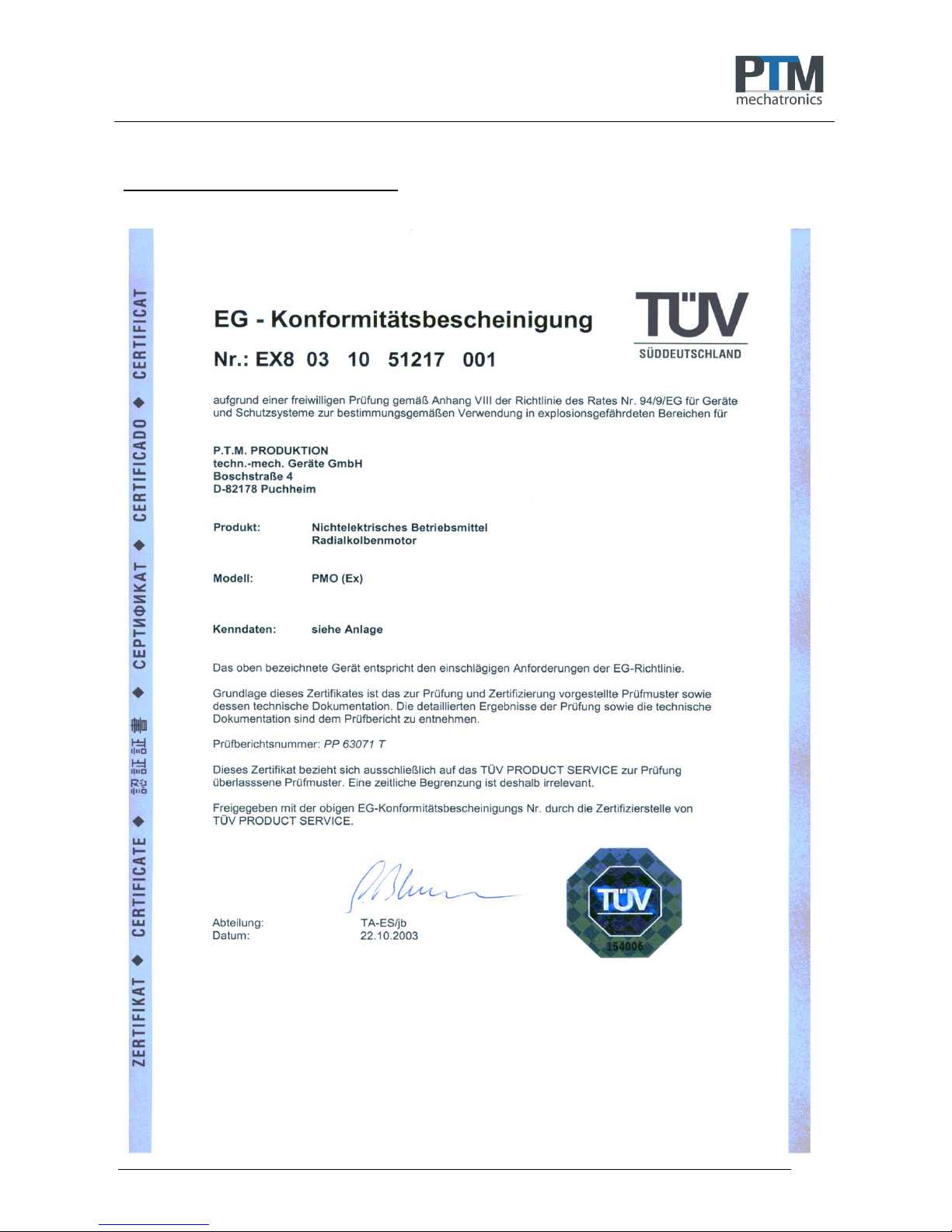
D.3 EG – Konformitätsbescheinigung
Page 17

Montageanleitung / Assembly guide
Seite 17 von 36
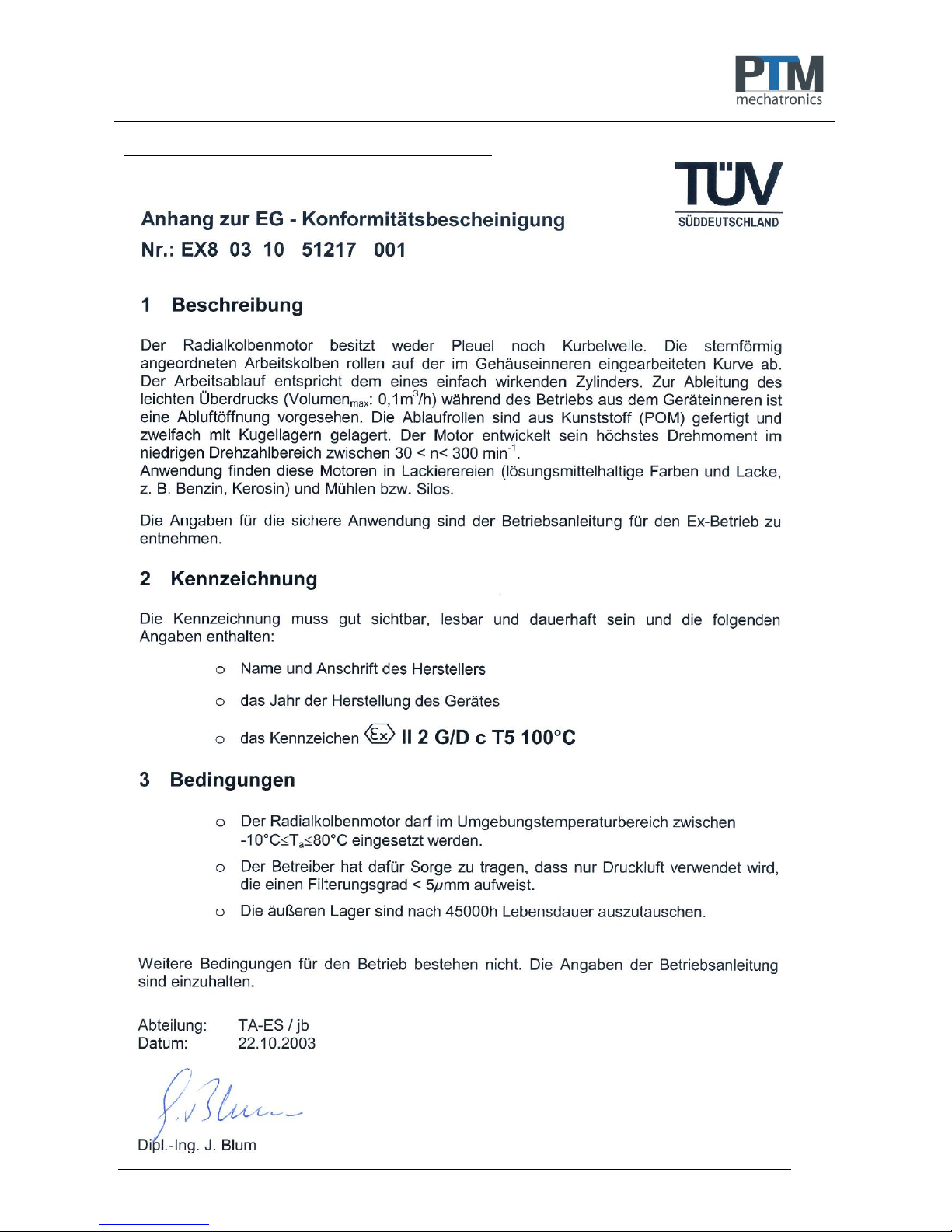
D.4 Anhang zur EG – Konformitätsbescheinigung
Page 18

Montageanleitung / Assembly guide
Seite 18 von 36
Certified in accordance with ISO 9001:2008
Assembly guide:
PTM air motor
PMO450 PMO900
PMO1450 PMO1800
PMO3600 PMO7200
Page 19

Montageanleitung / Assembly guide
Seite 19 von 36
Inhalt
A. INSTALLATION CERTIFICATE............................................................................................................ 20
A.1 Functional description ............................................................................................................................. 20
A.2 Manufacturer and customer service ........................................................................................................ 20
A.3 Important notes ....................................................................................................................................... 21
A.4 Versions .................................................................................................................................................. 23
A.5 General safety precautions ..................................................................................................................... 25
B. COMMISSIONING ................................................................................................................................ 26
B.1 Compressed air connection .................................................................................................................... 26
B.2 Repairs .................................................................................................................................................... 26
C. EX PROTECTION ................................................................................................................................ 27
C.1 General safety precautions ..................................................................................................................... 27
C.2 Motor versions ......................................................................................................................................... 27
C.3 Verification of Ex-protection .................................................................................................................... 27
C.4 Operation ................................................................................................................................................ 28
C.5 Principles ................................................................................................................................................. 28
C.5.1 European directives, laws and provisions ............................................................................................. 28
C.5.2 Marking in accordance with Directive 94/9/EG and 2014/34/EU .......................................................... 28
C.6 Explosion protection regulations ............................................................................................................. 28
C.6.1 Zone classification of potentially explosive areas ................................................................................. 28
C.7 Commissioning, installation .................................................................................................................... 29
C.7.1 Use, application conditions ................................................................................................................... 29
C.7.2 Ambient temperatures ........................................................................................................................... 30
C.7.3 Maximum surface temperature ............................................................................................................. 30
C.7.4 Temperature resistance ........................................................................................................................ 30
C.7.5 Maintenance, repair .............................................................................................................................. 30
C.7.6 Troubleshooting .................................................................................................................................... 30
C.7.8 Disposal ................................................................................................................................................ 30
D. APPENDIX .................................................................................................................................................. 31
D.1 Declaration of conformity ........................................................................................................................ 31
D.2 Declaration of Conformity ....................................................................................................................... 32
D.3 EG Certification of Conformity ................................................................................................................ 33
Page 20

Montageanleitung / Assembly guide
Seite 20 von 36
A. INSTALLATION CERTIFICATE
Our products are in principle developed and manufactured in compliance with the applicable directives and
standards. They are based on current knowledge and subject to modifications as well as improvements. Any
additions or revisions to the EU guidelines are taken into consideration. The original installation certificate as
defined by Directive 2006/42/EC for Machinery, Annex II Part 1 Section B is attached to this product.
Compressed air motors are non-electrical equipment in terms of incomplete machinery.
The devices are approved only for proper and intended use. Contraventions invalidate any warranty and
exempt the manufacturer from any responsibility!
The applicable national regulations must be observed prior to commissioning.
A.1 Functional description
The compressed air motor (radial piston motor) has neither a connecting rod nor crankshaft. The star-shaped
working pistons roll off a curve embedded into the inside of the casing. The compressed air required for the
drive operation reaches the working piston via a rotating control ring on the cylinder disc and a control shaft
fixed in the centre. Fresh air and exhaust air alternately supply and vent the pistons. By reversing supply and
exhaust air, right or left rotation can immediately be generated at motors that work without gears. Of the
seven pistons installed, three to four are always involved in generating the required torque. The pistons at the
highest curve point are vented and forced back to their initial position. The operating sequence corresponds
to that of a single-acting cylinder. To discharge the slight overpressure (volume max.: 0.1m3/h) occurring
during operation from inside the device, an exhaust air opening is provided. The feed rollers are
manufactured from heavy-duty plastic and are arranged on two sets of ball-bearings. That means there is
almost no friction and only a minimum roll-off noise. In contrast to conventional vane motors, the PMO
develops its highest torque in the low revolution range with very low air consumption. It can be used only
between 30 < n< 300 rpm. As a medium it uses treated, non-oiled compressed air at 2-6 bar and a filtration
degree of <=5µ.
A.2 Manufacturer and customer service
PTM mechatronics GmbH
Gewerbepark 1
D-82281 Egenhofen
Deutschland
Tel.: +49 8134 - 25797 - 0
Fax: +49 8134 - 25797 - 99
E-Mail: info@ptm-mechatronics.com
Internet: www.ptm-mechatronics.com
Please always indicate the device number when contacting the customer service.
Please contact our customer service before shipment of devices for repair or returns. Otherwise
consignments will not be accepted.
© PTM mechatronics GmbH
03/2017
Subject to modifications
Page 21
Montageanleitung / Assembly guide
Seite 21 von 36
A.3 Important notes
Compressed air
As a medium, only use treated, non-oiled compressed air at 2-6 bar and a
filtration degree of <=5µ.
Speed
Motor is to be used only between 30 < n< 300 rpm.
For protection against too high speed, we offer flow rate reductions.
When using transmission, final limit speed is
3:1 10 < n< 100 rpm
9:1 3.3 < n< 33 rpm
1:2 60 < n< 600 rpm
Agitator continuous
operation
At continuous operation in one rotation direction, the exhaust air duct needs
to be larger than the supply air duct.
When using silencers at the exhaust air, only high-performance silencers may
be used.
Dynamic pressure inside the motor must be avoided.
Housing ventilation
The housing must be able to vent during operation. Therefore, housing
ventilation may not be closed.
Page 22
Montageanleitung / Assembly guide
Seite 22 von 36
Page 23
Montageanleitung / Assembly guide
Seite 23 von 36
A.4 Versions
Dimensions:
with mounting flange: with mounting angle:
d 1
d 2
d 3
d 4
d 5
d 6
d 7
d 8
d 9
d 10
d 11
d 12
d 13
d 14
d 15
PMO 0450
99
14 h6
M 4x12
M 6x0,75x8
M 4x9
67
55 h6
40
28
M 5x5
87
5.4
110
120
5
PMO 0900
99
14 h6
M 4x12
M 6x0,75x8
M 4x9
67
55 h6
40
28
M 5x5
87
5.4
110
120
5
PMO 1800
159
19 h6
M 6x18
R1/8x9
M 6x10
115
95 h6
50
35
M 5x5
140
8.5
180
199
7
PMO 3600
159
19 h6
M 6x18
R1/8x9
M 6x10
115
95 h6
50
35
M 5x5
140
8.5
180
199
7
PMO 7200
159
19 h6
M 6x18
R1/8x9
M 6x10
115
95 h6
50
35
M 5x5
140
8.5
180
199
7
L 1
L 2
L 3
L 4
L 1 VA
L 2 VA
L 3 VA
L 5
L 6
L 7
L 8
L 9
L 10
L 11
L 12
L 13
L 14
PMO 0450
78
52
51 3 81
55
53.5
18
16
5 N9
11
25
12
39
99
89 5 PMO 0900
93
67
65 3 95.5
69.5
68
18
16
5 N9
11
25
12
54
99
89
5
PMO 1800
111
70
68 5 115
74
71.5
28
22
6 N9
15
40
13
55
159
140
9.5
PMO 3600
133
92
90 5 137
96
93.5
28
22
6 N9
15
40
13
77
159
140
9.5
PMO 7200
194
153
151
5
198
157
154.5
28
22
6 N9
15
40
13
138
159
140
9.5
L 15
L 16
L 17
L 18
L 19
L 20
L 21
L 22
L 23
L 24
W 1
W 2
W 3
PMO 0450
40
15
10
37
50
0.5
10
58 6 4 N9
45°
90°
45°
PMO 0900
40
15
10
37
50
0.5
10
58 6 4 N9
45°
90°
45°
PMO 1800
55
16
15
48
67
0.5
12
90 7 5 N9
45°
90°
45°
PMO 3600
55
16
15
48
67
0.5
12
90 7 5 N9
45°
90°
45°
PMO 7200
55
16
15
48
67
0.5
12
90
7
5 N9
45°
90°
45°
Page 24
Montageanleitung / Assembly guide
Seite 24 von 36
Abmessung
mit Getriebe
L 1
3:1
L 2
3:1
L 3
3:1
L 11
3:1
L 1
9:1
L 2
9:1
L 3
9:1
L 11
9:1
PMO 0450
120
94
93
81
104
78
77
65
PMO 0900
135
109
107
96
119
93
91
80
PMO 1800
161
120
118
105
137
96
94
81
PMO 3600
183
142
140
127
159
118
116
103
PMO 7200
244
203
201
188
220
179
177
164
Without gear
n min n max
= 30 rpm = 300 rpm
Reduction ratio 3 : 1
n min n max
= 10 rpm = 100 rpm
Reduction ratio 9:1
n min n max
= 3,3 rpm = 33 rpm
Reduction ratio 1:2
n min n max
= 60 rpm = 600 rpm
PMO 0450
4 Nm
2 Nm
12 Nm
6 Nm
36 Nm
18 Nm
2 Nm
1 Nm
PMO 0900
8 Nm
3 Nm
24 Nm
9 Nm
72 Nm
27 Nm
4 Nm
1,5 NM
PMO 1800
16 Nm
2 Nm
48 Nm
6 Nm
144 Nm
18 Nm
8 Nm
1 Nm
PMO 3600
32 Nm
3 Nm
96 Nm
9 Nm
288 Nm
27 Nm
16 Nm
1,5 Nm
PMO 7200
64 Nm
6 Nm
194 Nm
19 Nm
576 Nm
54 Nm
32 Nm
3 Nm
max.
allowed
axial loading
radial
dyn. C
radial
stat. Co
max.
allowed
radial loading
weights
without with with with
gear 3:1 gear 9:1 gear 1:2 gear
PMO 0450
100 N
750 N
400 N
5 Nm
1.10 Kg
2.00 Kg
2.80 Kg
2.10 Kg
PMO 0900
100 N
750 N
400 N
5 Nm
1.30 Kg
2.20 Kg
3.00 Kg
2.30 Kg
PMO 1800
200 N
1500 N
800 N
10 Nm
3.40 Kg
6.10 Kg
7.90 Kg
5.90 Kg
PMO 3600
200 N
1500 N
800 N
10 Nm
4.00 Kg
6.70 Kg
8.50 Kg
6.50 Kg
PMO 7200
200 N
1500 N
800 N
10 Nm
6.40 Kg
9.10 Kg
10.90 Kg
8.90 Kg
Page 25

Montageanleitung / Assembly guide
Seite 25 von 36
A.5 General safety precautions
The installation instructions are to be read by the motor operator prior to commissioning and the precautions
observed during operation.
14. The motor can be used in any position.
15. Check that all packaging and contamination protection residues have been removed.
16. Make sure that all connections and joints are correctly made.
17. The tamperproof seals must not be damaged.
18. Repairs are reserved for the manufacturer.
19. Observe Directive 1999/92/EC (employee health and safety)
20. Do not exceed the maximum operating pressure of 6 bar.
21. Minimum operating pressure is 2 bar.
22. Do not exceed the maximum motor speed of 300 rpm. Danger of total destruction.
23. Geared motors may only be reversed if the motor is at standstill
24. Use non-oiled, dried compressed air with a filtration of <= 5µ.
25. Temperature application range is -10°C to +80°C
26. Check the delivery against your order and the delivery note with serial number for authenticity and
completeness.
Strict compliance to the accident prevention regulations and any additional national safety regulations is
required at all times.
Page 26

Montageanleitung / Assembly guide
Seite 26 von 36
B. COMMISSIONING
B.1 Compressed air connection
The function and the service life largely depend on the quality and pressure of the compressed air supplied.
Excessive moisture or dirt particles damage the motor. A high proportion of condensate in the compressed air
causes rust to form in the motor and the silencer freezes up when the air expands.
The following points are to be observed when using the compressed air motor:
For the supply and exhaust air to/from the motor, use the right air hose (see table)
PMO450 PMO900
PMO1450 PMO1800 PMO3600
Air supply diameter 6mm
Air supply diameter 8mm
Air exhaust diameter 8mm
(at continuous operation in one direction of rotation)
Air exhaust diameter 10mm
(at continuous operation in one direction of
rotation)
Reduce to smaller diameter required immediately before the motor’s compressed air connections.
Various adapter versions are available as accessories for this purpose.
The M5 vent hole for the overpressure generated inside the compressed air motor must never be sealed
off. Use a vent hose with an inside diameter of 3 mm.
Main air lines require a slight gradient of at least 1% in the direction of flow to allow condensate to drain
at the lowest position through a valve (manual or automatic).
For a horizontal main line, connect the branches from above. For a vertical main line, do not connect at
the lowest position. That will prevent condensate present in the main line from flowing into the branch.
Use maintenance units with an air filter of min. < 5µ filtration degree. Install the maintenance unit with a
minimum ¼" threaded air connection in the vicinity of the motor.
When used under water it is essential to observe correct dried, cooled compressed air to avoid the formation of
condensate.
The air filter requires regular maintenance during which the stored condensate must be drained and the
filter cleaned.
The compressed air motor achieves its optimum performance at 6 bar (85 psi). If the pressure in the
compressed air network exceeds 6 bar, a pressure regulator must be used.
The required number of revolutions can be set using the pressure regulator or a supply or exhaust air
throttle. The supply air throttle is preferred over the exhaust air throttle as less wear occurs.
A speed of over 300 rpm and hence damage to the motor must be prevented at all costs, both without
load and under load.
B.2 Repairs
If the compressed air motor does not achieve the required output, check the following points:
g) Is the air pressure adequate (6 bar / 85 psi)?
h) Is the air pressure constant or does it fluctuate?
i) Is the required air quantity available?
j) Is the air filter in the maintenance unit clean?
k) Are there any leak losses between the maintenance unit and compressed air motor?
l) Are there cross-sectional constrictions in the exhaust air line?
If none of these faults is present, the motor must be returned to the manufacturer for inspection.
Please have all repairs carried out by the manufacturer. The seals must not be damaged.
Page 27

Montageanleitung / Assembly guide
Seite 27 von 36
C. EX PROTECTION
For use in potentially explosive areas.
C.1 General safety precautions
The installation instructions are to be read by the motor operator prior to commissioning and the precautions
observed during operation.
Only operate the motor in explosion protected systems.
Create equipotential bonding. (on the rear of the motor using the M4 lens head screw)
Only use conductive air hoses.
Compressed air generated and treated outside the Ex-area is used as a medium.
Vent the housing vent via the M5 connection outside of the potentially explosive area.
Strict compliance to the accident prevention regulations and any additional national safety regulations is
required at all times.
C.2 Motor versions
Compressed air motors are non-electrical equipment and do not require approval when used in
Zones 1 and 21.
The compressed air motors are available in various designs and upgrades.
These motors are used, for instance, in paint shops (solvent-based paints and coatings, e.g. petrol, kerosene)
and mills, silos etc.
The qualification with regard to the surface temperature is T5; for all gases, vapours and mists with an ignition
temperature > 100°C, the devices are no ignition sources. In the dust ex-area, 100°C is the reference
temperature for further considerations with respect to a safety clearance from the smouldering temperature. A
decision can be made only by the operator.
The gearbox mounted to the radial piston motor is a planetary gearbox. It reduces the drive speed for each
gear setting by one third and increases the max. torque by a factor of 3.
ATTENTION! Change direction of rotation only after the motor is stopped to standstill. See A.1 / 10
The PMO radial piston motor with or without mounted gearbox can be used as follows:
o In Zone 1 (gas-ex, Category 2G) in explosion group IIA and IIB.
o In Zone 21 (dust-ex, Category 2D) for non-conductive dusts with a minimum ignition energy > 3 mJ
C.3 Verification of Ex-protection
Prior to commissioning in a potentially explosive environment, verification of the following is required:
5. compressed air motor explosion-protected?
6. System explosion-protected?
7. Equipotential bonding created?
8. Conductive hoses and hose connections used?
Page 28

Montageanleitung / Assembly guide
Seite 28 von 36
C.4 Operation
When used in potentially explosive areas, the ball bearings must be replaced after 45,000 hours of operation
at the latest.
C.5 Principles
Given the planned use of the radial piston motors and gearbox in a potentially explosive area, the following
EU Directive is decisive:
C.5.1 European directives, laws and provisions
94/9/EC and 2014/34/EU: European Explosion Protection Directive
C.5.2 Marking in accordance with Directive 94/9/EG and 2014/34/EU
The marking of the non-electrical equipment is:
II 2 G/D c T5 100°C
C.6 Explosion protection regulations
For equipment in potentially explosive areas, the operator is required to comply with a number of regulations.
The list below shows the key regulations at a glance:
The following applies within the European Union:
- >Directive 1999/92/EC regarding minimum regulations for improving health safety and the safety of
employees who can be endangered by potentially explosive atmospheres.
- >EN 50014
- Electrical equipment for potentially explosive areas – General Provisions
- >EN 60079-14 (IEC 60079-14)
- Electrical equipment for potentially explosive areas – Part 14: Electrical systems in potentially explosive
- areas
- >EN 60079-10 (IEC 60079-10)
- Electrical equipment for potentially explosive areas – Part 10: Classification of potentially explosive
- areas
- >DIN EN 1127-1
- Potentially explosive atmospheres – Explosion protection - Part 1: Principles and methods
- >DIN EN 13463-1
- Non-electrical equipment for use in potentially explosive areas – Part 1: Principles and requirements
- >DIN EN 13463-5
- Non-electrical equipment for use in potentially explosive areas – Part 5: Protection through safe
- construction
Additional national regulations and directives can also apply.
C.6.1 Zone classification of potentially explosive areas
Potentially explosive areas are areas in which potentially explosive atmospheres can occur in hazardous
amounts due to the local and operational circumstances. These areas are subdivided into several zones.
Page 29

Montageanleitung / Assembly guide
Seite 29 von 36
For potentially explosive areas due to combustible gases, vapours or mist:
d) Zone 0/20 – includes areas in which hazardous potentially explosive atmospheres are present constantly
or over the long term.
e) Zone 1/21 – includes areas in which hazardous potentially explosive atmospheres can be expected to
occur occasionally.
f) Zone 2/22 – includes areas in which hazardous potentially explosive atmospheres can be expected to
occur only seldom and even then only for a brief period.
C.7 Commissioning, installation
Radial piston motor and gearboxes feature housings to protection class IP 67 and/or IP 68, which guarantee
the IP protection required. The operator must specify the time required to clean the equipment of dust
deposits irrespective of the above and depending on the application conditions.
Other key facts:
o Experts may place the device in operation in Category 2 (Zone 1 or 21).
o Closures must be re-attached after opening and closing.
o Supply air and exhaust air openings must not be closed.
o The devices are approved only for operation with compressed air to at least Quality Class 5 in
accordance with ISO 8573-1 that has been generated and treated outside the Ex-area. The use of
liquids and gases is not considered within the boundaries of intended use. Requirements are stated in
the Installation Instructions.
o Ignitable sparks can be produced when discharging electrostatically charged parts. Operation of the
devices with hoses and hose bundles up to a maximum outside diameter of Ø 20 mm is permitted.
o During operation, an effective equipotential bonding is to be created using the earthing screw on the
housing.
o Impact involving rust and light metals or their alloys can generate ignitable sparks. The use of tools with
corroded surfaces is prohibited. The devices must be protected against falling objects.
o Potentially explosive atmospheres or potentially explosive dusts must not penetrate the housing.
o Operation of the device is permitted only when the housing is fully closed and intact.
o Operation with a damaged housing is prohibited.
o Compressed air must not be blown out into areas containing potentially explosive atmospheric dusts.
The exhaust air lines must be routed outside of the Ex-area.
o Corrosion, wear and other reciprocal effects must be taken into account in the choice of substances,
materials and fittings.
o The number and choice of detachable connections must be kept to a minimum, hose connections must
be kept as short as possible and mechanical stresses avoided.
o The equipment satisfies the requirements of IP 67 and/or IP 68 for housings and side panels. No
additional protection is required against moisture.
C.7.1 Use, application conditions
o The devices are approved only for proper and intended use. Contraventions invalidate any warranty and
exempt the manufacturer from any responsibility!
o Only those accessories that satisfy all the requirements of the European Directives and the national
legislation concerned are permitted for use in potentially explosive areas.
o The radial piston motor for driving the gearbox may be employed up to a maximum overpressure of 6
bar. The maximum speed of the radial piston motor is 300 rpm, the maximum gearbox speed is 100 rpm.
o A hazardous electrostatic discharge directly onto the equipment is not permitted. Under normal
circumstances, such discharges cannot be generated by humans, they require a compressed air nozzle
or similar.
o Use in the dust ex-area is permitted for non-conductive dusts with a minimum ignition energy > 3 mJ.
o The ambient conditions specified in the Mounting Instructions must be respected at all times.
o Lightning protection measures must be guaranteed by the operator.
Page 30

Montageanleitung / Assembly guide
Seite 30 von 36
C.7.2 Ambient temperatures
At -10°C ≤ Ta ≤ +80°C, the stated ambient temperature range differs from the standard temperature range.
C.7.3 Maximum surface temperature
The temperature measurements on the motor, gearbox housing and control shafts were taken at ambient
temperatures of between 21°C and 24°C. A maximum heat-up, assuming the worst possible operating
conditions (maximum load: 2 Nm; speed 300 rpm), of 8.7°C was measured on the control shaft. No significant
temperature fluctuations were detected during the further course of the 60-hour measurement.
C.7.4 Temperature resistance
Non-metallic housing parts must be resistant to hot and cold temperatures such that the degree of protection
is not reduced. Plastics must have a temperature index TI consistent with the 20,000h point, which is at least
20K higher than the local maximum surface temperature, taking into account the maximum ambient
temperature. All the plastics used have a continuous working temperature of at least 100°C and hence
comply with the set requirements.
C.7.5 Maintenance, repair
o Maintenance activities may only be carried out by PTM mechatronics GmbH itself or by persons who
have been specially trained by PTM mechatronics GmbH.
o Components may be replaced only with genuine spare parts, which are also approved for use in the Ex-
area. This also applies to the used lubricants and excipients.
o The devices in the Ex-area must be regularly serviced and cleaned. The intervals are specified by the
operator in accordance with the local environmental conditions, e.g. a dust deposit of approx. 0.5 - 1
mm.
o On completion of maintenance and/or repair work, all barriers and/or notices removed during the
process must be re-attached at their original position.
o Dust deposits in gaps between moving parts are capable of warming up. The spaces between rotating
parts must be cleaned on a regular basis.
o The mounted outer bearings must be replaced after 45,000 hours of operation and outside of potentially
explosive atmospheres.
o Radial piston motors and gearboxes may only be cleaned outside of potentially explosive atmospheres.
C.7.6 Troubleshooting
No modifications may be made to devices that are operated in potentially explosive areas. Repairs to the
device may only be carried out by PTM mechatronics GmbH.
C.7.8 Disposal
Packaging and used parts must be disposed of in accordance with the provisions of the country in which the
device is installed.
Egenhofen, 01.03.2017
Carsten Angermeyer, Managing Director subject to modifications
Page 31
Montageanleitung / Assembly guide
Seite 31 von 36
D. APPENDIX
D.1 Declaration of conformity
Installation Declaration ("Original Installation Declaration")
as defined by Directive 2006/42/EC for Machinery, Appendix II Part 1 Section B
We, as manufacturer, declare that for the equipment/incomplete machine described below
DESIGNATION
TYPE
SERIAL NO.:
ITEM NO.:
Pneumatic Radial Piston Motors
PMO
PMO0450; PMO0900; PMO1450;
PMO1800; PMO3600; PMO7200
PMOxxxx-x-x-xxx-x
In explosion-proof version
PMO
PMO0450; PMO0900; PMO1450;
PMO1800; PMO3600; PMO7200
PMOxxxx-x-x-x1x-x
Radial piston motor as non-electrical equipment for the drive by compressed air in different versions and sizes.
Alternatively in EX-version, with and without gear box.
1. the following health and safety requirements as per Appendix I in accordance with Directive 2006/42/EC
are applied and respected:
Nr. 1: General principles,
Nr. 1.1.2: Principles of safety integration,
Nr. 1.1.3: Materials and products,
Nr. 1.1.5: Design of machinery to facilitate its handling,
Nr. 1.2.3: Starting,
Nr. 1.2.6: Failure of the power supply,
Nr. 1.3.2: Risk of break-up during operation,
Nr. 1.3.3: Risks due to falling or ejected objects,
Nr. 1.3.4: Risks due to surfaces, edges or angles,
Nr. 1.5.2: Static electricity,
Nr. 1.5.6: Fire,
Nr. 1.6.3: Isolation of energy sources,
Nr. 1.6.4: Operator intervention.
2. the special technical documents have been prepared as per Appendix VII Part B in accordance with
Directive 2006/42/EC.
We also commit to transmitting to the responsible authority(ies) the aforementioned special technical
documents on receipt of a justified request in the form of / via CAD.
They can be requested from: PTM mechatronics GmbH, Gewerbepark 1, 82281 Egenhofen - Deutschland
The commissioning of incomplete machines/equipment is forbidden and unacceptable until the machine, into
which the incomplete machine/equipment is to be integrated, satisfies the provisions of Directive 2006/42/EC.
Egenhofen, 01.03.2017
Carsten Angermeyer, Managing Director
Page 32

Montageanleitung / Assembly guide
Seite 32 von 36
D.2 Declaration of Conformity
Page 33
Montageanleitung / Assembly guide
Seite 33 von 36
D.3 EG Certification of Conformity
Page 34
Montageanleitung / Assembly guide
Seite 34 von 36
D.4 Appendix to EG Certification of conformity
Page 35

Montageanleitung / Assembly guide
Seite 35 von 36
Page 36

Montageanleitung / Assembly guide
Seite 36 von 36
PTM mechatronics GmbH
Gewerbepark 1
D-82281 Egenhofen
Deutschland
Tel.: +49 8134 - 25797 - 0
Fax: +49 8134 - 25797 - 99
E-Mail: info@ptm-mechatronics.com
Internet: www.ptm-mechatronics.com
 Loading...