

PTF 3203A Operation And Maintenance Manual
Document #: 11492
ptf
ptf 3203A
Operation and Maintenance Manual
Revision: S

Certificate of Conformance
This certificate confirms that the following equipment:
Unit type: ptf 3203A GlobalTyme GPS Receiver
Serial Number: ________ __________________
has successfully passed a FINAL ACCEPTANCE TEST and conforms
in all respects of form, fit, and function to current specifications, including
regulatory requirements and certifications.
Inspected and verified by: Date:
_____________________ _____________________
For Precise Time and Frequency, Inc

Declaration of Confor mity
This certificate confirms that the following equipment:
Unit type: ptf 3203A
is in conformity with the relevant provisions of the following standard(s)
or other normative document(s):
EU EMC Directive 2004/108/EC:
ETSI EN 301 489-1, V1.8.1 (2008-04}
Electromagnetic compatibility and Radio spectrum Matters (ERM);
Electromagnetic Compatibility (EMC) standard for radio equipment and services;
Part 1: Common technical requirements
EN 55022:2006
Information technology equipment — Radio disturbance characteristics - Limits
and methods of measurement
EN 61000-4-2: 2001
Electromagnetic compatibility (EMC) - Part 4-2: Testing and measur eme nt
techniques - Electrostatic discharge immunity test
EN 61000-4-3:2006
Electromagnetic compatibility (EMC) - Part 4-3: Testing and measur eme nt
techniques - Radiated, radiofrequency, electromagnetic field immunity test
EN 61000-4-4:2004
Electromagnetic compatibility (EMC) - Part 4-4: Testing and me asurement
techniques - Electrical fast transient/burst immunity test
EN 61000-4-5:2006
Electromagnetic compatibility (EMC) - Part 4-4: Testing and measur eme nt
techniques - Surge immunity test
EN 61000-4-6:2005
Electromagnetic compatibility (EMC) - Part 4-4: Testing and measureme nt
techniques - Electrical fast transient/burst immunity test
EN 61000-4-11:2004
Electromagnetic compatibility (EMC) - Part 44: Testing and me as urement
techniques — Voltage Dips and Short Interruptions immunity test
ISO 7637-2:2004
Road vehicles - Elec t ri c al dist ur b ances from conduction and co upli n g - Part 2:
Electrical transient conduction along supply lines only
EN 61000-3-2:2006 +A1:2009 +A2:2009

Electromagnetic compatibility (EMC) - Part 32: Limits - Limits for harmonic and
current emissions (equipment input current ≤ 16 A per phase)
EN 61000-3-3:1995
Electromagnetic compatibility (EMC) - Part 3-3: Limits - Limitation of voltage
changes, voltage fluct u ati ons and flicker in public low -voltage supply systems, for
equipment with rated current ≤ 16 A per phase and not subject to condition al
connection
EN 55016-1-1:2007
Specification for radio disturbance and immunity measuring apparatus and
methods — Part 1-1: Radio disturbance and immunity measuring apparatus —
Measuring apparatus Amendment1 ( 2007)
ClSPR16-1-2:2003
Specification for radio disturbance and immunity measuring apparatus and
methods — Part 1-2: Radio disturbance and immunity measuring apparatus —
Ancillary equipment — Conducted disturbances 5
Amendment1 (2004)
Amendment 2 (2006)
EN 55016-1-4:2007
Specification for radio disturbance and immunity measuring apparatus and
methods - Part 1-4: Radio disturbance and immunity measuring apparatus Ancillary equipment - Radiated disturbances
EN 55016-2-3:2004
Specification for radio di s tur ba nc e and immu ni ty measuring apparatus and
methods - Part 2-3: Methods of measurement of disturbances and immunity —
Radiated disturbanc e meas ur e men ts
Amendment 1 (2005)
EN 55016-4-2:2003
Specification for radio disturbance and immunity measuring apparatus and
methods — Part 4-2: Uncertainties, statistics and limit modeling —
Measurement instrumentation uncertainty
EU Low Voltage Directive 2006/95/EC
EN 60950-1:2006 Safety of Information Technology Equipment,
+A1+A11+A12 including electrical business equipment
EU ROHS directive compliance according to Directive 2002/95/EC

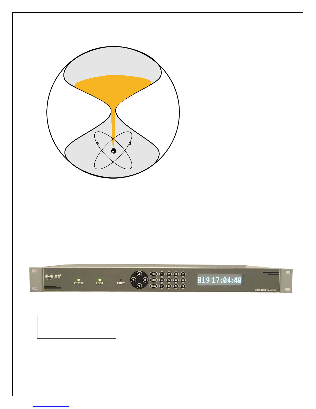
Introduction
Congratulations on your purchase of the ptf 3203A Global Ty me mul ti func ti o n
GPS receiver !
This product meets the highest standards of quality and reliability, and Precise
Time and Frequency, Inc wants to insure that you enjoy the maximum benefits
and functionality that this unit can provide.
The technology within this unit uses the decades of experience in time and
frequency applications of our engineering team, to provide a unit that is highly
advanced, and gives a very powerful feature set in an inexpensive and compact
package,
Operation of the unit is straightforward and the contents of this manual are
designed to provide a basic understanding of the product, set-up and
functionality, and procedures for maintenance and repair.
If you have any questions or concerns, please do not hesitate to contact our
technical service department who will be pleased to provide assistance.
Please help us to live up to our stated objectives, our company motto is:
KNOW THE NEEDS AND EXPECTATIONS OF YOUR CUSTOMER…THEN DELIVER!
Once again, thank you for purchasing our product, and we look forward to you
utilizing Precise Time and Frequency, Inc. for your future time and frequency
instrumentation ne eds.
President
Precise Time and Frequency, Inc.
50L Audubon Road, Wakefield, MA 01880, USA
Tel: (+1) 781 245 9090 Fax: (+1) 781 245 9099 e-mail: info@ptfinc.com
www.ptfinc.com

CONTENTS
This manual is applicable to ptf 3203A and ptf units fitted with software
version 23 – 2 and abov e.
1. GPS Satellite System Desc r i pti on
2. Technical Overview
3. Specifications
4. Unpacking/Inspection/Installation
5. Operation
6. Maintenance
7. Contact Information – Technical Assistance

1. GPS Satellite System Description
The Global Positioning System (GPS) satellites consist of a constellation of
satellites orbiting at an altitude of 10,400 miles above the earth, each satellite
completing one orbit every 12 hours. Ground-based contr ol / m oni tor s tati ons
monitor the health of each of the satellites, as well as providing precision
timing updates on a regular basis.
The satellite system comprises 24 satellites in six orbital planes inclined at
around 60 degrees to the equator, and provides positioning, velocity, and time
to user equipment worldwide.
GPS satellite positions are known to an accuracy of a few meters, and each
satellite carries an ensemble of atomic clocks that are maintained to an
accuracy of a few nanoseconds. Now that the selective availability function of
the GPS satellites has been disabled, this allows receiver position to be
calculated to an accuracy of approximately 10 meters
The signal transmitted from each satellite consists of two carrier frequencies,
referred to as L1 and L2. The L1 frequency is 1575.42 MHz and the L2
frequency is 1227.6 MHz. To provide enhanced performance for military and
other (US Government Authorized) users the L1 signal is modulated with a
precision (P) code, and also a coarse acquisition (C/A) code.
The GlobalTyme operates on the C/A code transmitted from each satellite.
This C/A code, which is unique for each satellite, contains information on the
satellite identity for acquisition and tracking. The C/A pseudo random number
(PRN) code is a 1023 bit code that repeats at the rate of every millisecond.
Operating on the L1 band and utilizing the C/A code transmissions, the ptf
3203A GlobalTyme determines time and frequency by measuring the time of
arrival of a precise timing mark transmitted by each of the satellites, and
computing the time against it’s known (previously determined and entered)
position. This is the basis for the GlobalTyme’s one pulse per second (1PPS)
output.
As the GlobalTyme time and frequency outputs are determined from satell it e
transmissions calculated and referenced to the United States Naval
Observatory (USNO) through the GPS Master Clock System, then traceability
to International Time Scales is provided through data provided by the USA’s
National Institute of Standards and Technology (NIST) and the international
timekeeper, the Bureau Internationale des Poids et Measures (BIPM) in
France.
2. ptf 3203A GlobalTyme - Technical Overview
The GlobalTyme automatically acquires and tracks satellites based on health
status and elevation angle. To undertake an accurate, three dimensional
(latitude, longitude, altitude) position fix, and the unit requires transmissions
from at least four satellites. Once accurate position data has been
automatically acquired, or manually entered, provision of accurate time and
frequency outputs requires only one satellite.
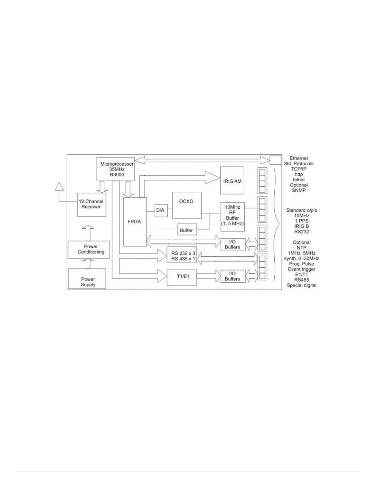
Figure 1. ptf 3203A Global Ty me Sc he matic
2.1. Technical Description
The ptf 3203A GlobalTyme multifunction GPS receiver architecture is
based upon a 35MHz microprocessor interfacing to a standard 12
channel GPS receiver and an FPGA to provide the range of functionality.
The GPS receiver input comes from a bullet antenna with 35 dB gain
(supplied) connected by means of a 30ft coax cable and TNC input
connector to the unit chassis.

Position information (required for accurate time capture) is automatically
acquired by the unit, or can be manually entered through the set up
controls.
The local oscillator fitted can be a TCXO, OCXO or Rubidium. The
oscillator is locked to the GPS 1PPS signal by means of a phase locked
loop and provides a good quality 10MHz sine wave output, buffered
through an RF buffer, to give a standard 1V rms, 13 dBm, 50 ohm output
impedance RF signal onto a BNC output connector.
GPS status and health is internally monitored and reported on front panel
LED’s (power, lock, and fault LED indicators). Ethernet and RS232
monitor/control i/o ports also report antenna fault status. In addition the
unit provides a “holdover” clean contact closur e on a rear panel
connector.
The FPGA provides a number of additional internally generated functions
including digital i/o capability (E1/T1 telecom, RS485, additional RS232,
event timer, programmable pulse rate) which are optionally made
available on the unit rear panel if required.
Due to the flexibility provided by the FPGA architecture, and available
built in i/o buffers, ptf is able to implement special i/o functions upon
request. If ordered with this unit, details of any special i/o functions, if any,
will be found in the appendix to this manual.
Standard unit set-up, monitoring and control is via either the RS 232 (DB9
connector) or Ethernet (RJ 45 connector) interfaces, which allow access
utilizing http, or telnet protocols. SNMP is optionally available.
Standard unit output func ti on al i ty includes:
12 Channel GPS engine to provide internal time and frequency
reference information, including range autonomous integrity
monitoring (RAIM).
10MHz, 1V rms RF sine wave output into 50 ohms
1 PPS ttl output
IRIG B (AM) output

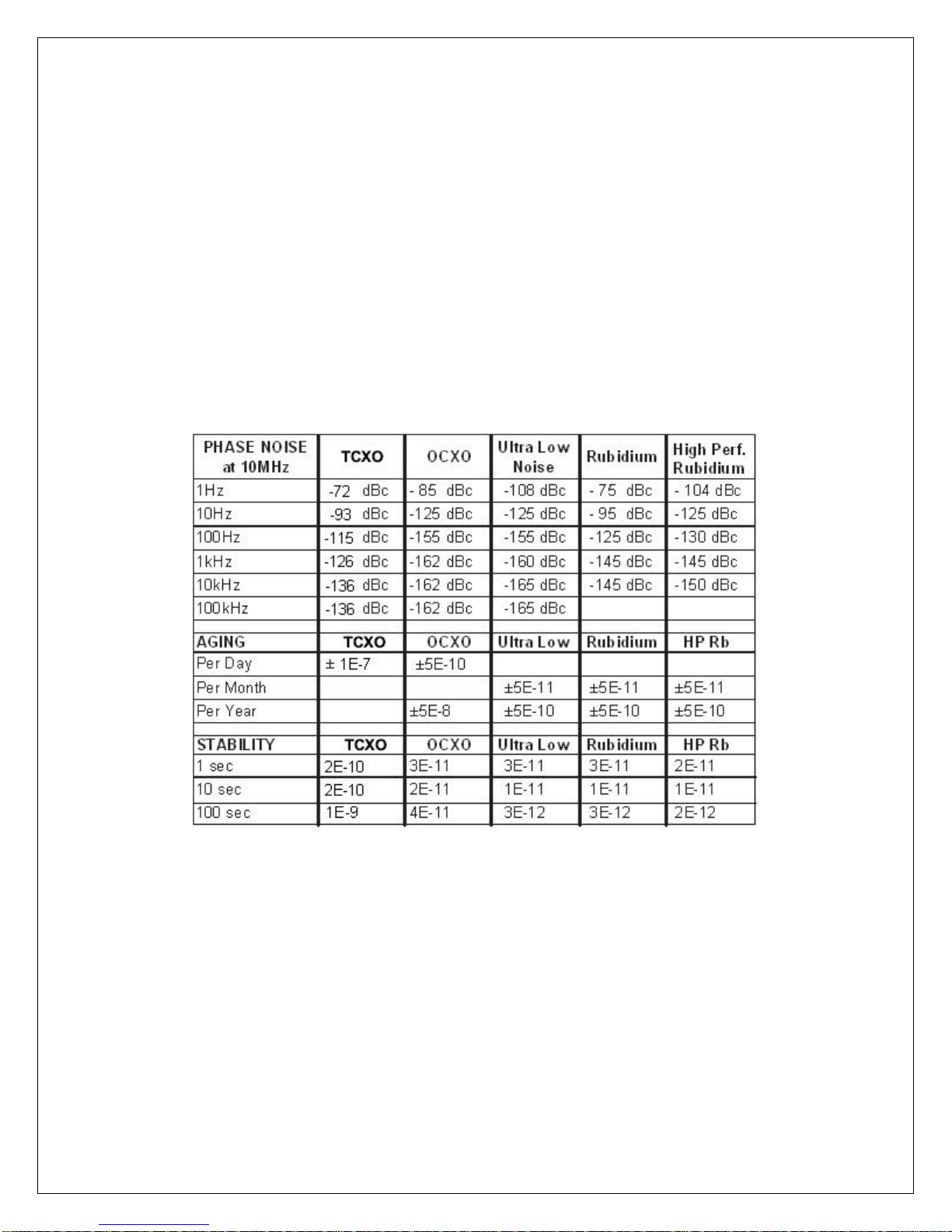
2.2. ptf 3203A GlobalTyme - Disciplining Algorithm
One of the most fundamental benefits of a GPS time and frequency system is
the attainable accuracy and stability of the generated RF frequency outputs.
The RF output is derived from an internal oscillator, and depende nt upo n the
requirements of the application this oscillator can be either a temperature
compensated quartz oscillator (TCXO), an oven controlled quartz oscillator
(OCXO), or a rubidium atomic oscillator.
In order to realize the benefits of the excellent long-term accuracy of the
received GPS signals, the internal oscillator is “disciplined” (controlled) by the
GPS signal, to insure it is centered on exactly the right frequency. The
narrower the bandwidth of the disciplining loop, the more accurate is control
of the local oscillator to the desired frequency, however this disciplining has to
be implemented with great care, as the noise of the incoming GPS signal can
cause the disciplining control loop to become unstable if the bandwidth of the
loop is too narrow.

3. ptf 3203A GlobalTyme - Specifications
3.1.1. GPS Sub-system (S/A off)
Receiver Architecture 12 parallel channels
L1 1575.42 MHz
C/A code (1.023 MHz chip rate)
Code plus carrier tracking
(carrier aided tracking)
Acquisition Time 200s TTFF-cold (with current almanac,
(Time To First Fix, TTFF) position, time and ephemeris)
50s TTFF-warm (with current almanac,
position, and time)
25s TTFF-hot (No stored information)
Time Accuracy <10 ns 1 sigma average
<20 ns 6 sigma average
Position Accuracy <10 meters after 24 hr aver ag i ng
Tracking Channels 12 Parallel
Dynamic Characteristics:
Velocity 1000 knots (515 m/s) maximu m
at altitudes < 60,000 ft.
Acceleration 4g maximum
Jerk 5 m/s3
Vibration 7.7G rms perMilitary Standard 810E
Antenna Bullet antenna, 37dB gain, 30 ft cable
3.1.2. Timing and Frequency Outputs, J1 thru J3
The standard ptf 3203A GlobalTyme includes a 10MHz sine wave,
1 pulse per second (PPS), and IRIG B (amplitude modulated),
outputs.
Additional outputs or inputs may be available if requested on
connectors J4 thru J8 – see appendix.
J1 – 10 MHz sine wave
Amplitude 1V rms into 50 ohm (13dBm)
Accuracy, Long Term < 1 E -14
(locked to GPS)
J2 – 1 PPS
Amplitude 4V into 50 ohm
Pulse width >25 micro secs. , < 50 micro secs.
Rise/Fall time < 6 ns
Trigger Positive (rising) edge
J3 – IRIG B (amplitude modulated)
Carrier frequency 1 kHz
Modulation Ratio 3 : 1
Amplitude 3V p-p (mark)
Table 3.1

J4 – Programmable Pulse Rate
The default output for J4 is a programmable pulse rate. Please note
that if special i/o has been specified, J4 may be allocated to
another function. Please refer to appendix for details.
Pulse Rate 1 PPS to 10 MPPS
Amplitude 4V into 50 ohm
Duty Cycle 1 : 1
J5 – Programmable Event Tri g g er
The default output for J5 is a programmable event trigger. Please
note that if special i/o has been specified, J5 may be allocated to
another function. Please refer to appendix for details.
Pulse Rate 1 PPS to 1 Pulse per day
Amplitude 4V into 50 ohm
Pulse width >25 micro secs. , < 50 micro secs.
Rise/Fall time < 6 ns
Trigger Positive (rising) edge
3.1.3. Control/Monitor i/o
Control/monitor fu ncti o ns are available on a rear panel mounted
DB9 RS232 connector. Allowing full remote monitoring and control
of the available unit functi ons.
Details and set up of the functions available on this interface can be
found in section 5.3 of this manual.
3.1.4. 100/10 Base T Ethernet
Control/monitor functions are also available on a rear panel
mounted RJ-45 Ethernet connector. Allowing full remote monitoring
and control of the available unit functions, together with optionally
providing Network Time Protocol (NTP).
Details and set up of the functions available on this interface can be
found in section 5.4 of this manual.
(settable)

3.1.5. Power Input
Standard AC power input:
Input voltage 100 to 240 V AC
Input Frequency range 50 to 60 Hz
(optional DC input)
Input voltage 18 to 52 V DC
3.1.6. Dimensions
Chassis Height 1.75 Inches.
Width 17 Inches. (19 inches with
rack ears)
Depth 12 Inches Maximum.
3.1.7. Weight
Chassis < 10 pounds
Antenna < 1.5 pounds
3.1.8. Environmental
Temperature
Chassis operating 0 to +50 deg. C
Chassis storage -20 to +85 deg. C
Antenna operating -40 to +85 deg. C
Humidity
Chassis to 95% RH non-condensing
Antenna Unlimited
3.1.9. NTP Outputs
NTP Version 3
Responds to Unicast and Anycast client requests
Multicast optionally on at user specified interval
Accuracy is approximately 100 nanoseconds

4. Unpacking/Inspection/Installation
4.1. Unpacking/Inspection
The ptf 3203A GlobalTyme together with accessories, is shipped in a
custom designed package. Upon receipt the equipment should first be
visually inspected for any signs of visible damage.
If visible damage is apparent immediate notification should be given to
both Precise Time and Frequency, Inc., and the carrier responsible for
shipment. Do not discard the shipping container, which should be made
available for inspection by the carrier.
For purposes of unit reference, the unit serial number located on the rear
panel of the unit should be quoted in all communications.
The equipment must be installed correctly and should be installed only by
qualified technical per sonnel.
This product is also designed for IT power distribution systems with
phase-to-phase voltage of 230V.
Warning: If connected to an IT power distribution system, the unit
is still under voltage even after operation of the protective fuses.
BNC Input/output connections are designed for connection to local
equipment with the same or adjacent racks, and are not intended for
connections outside o f a local bui l ding.
Similarly, the RS232 is for connection to a local terminal and the RJ45
Ethernet connector is for connection to a locally situated, approved basic
insulated router or switch.
4.2. Chassis Installation
The ptf 3203A GlobalTyme chassis is supplied with rack ears ready for
simple installation into a standard 19-inch rack frame/cabinet.
For adequate support when mounted into the rack, a rear supporting bar
or tray should be used as the rack ears are designed to secure the unit in
the rack, NOT to support the full weight of the unit.
Attention should be given to the internal rack environment to insure the
unit operates within it’s specified operating temperature range of 0 to 50

deg. C also noting that the unit relies upon convection for cooling, so
there should be sufficient air flow to accommodate this.
4.3. Antenna Installation
Careful attention to antenna installation is critical for obtaining the
best performance from this equipment.
Equipment connected to the protective earthing of the building installation
through the mains connection or through other equipment with a
connection to protecti ve earthing – and to a cable distributi o n sy s tem
using coaxial cable, may in some circumstances create a fire hazard.
Connection to a cable distribution system has therefore to be provided
through a device providing electrical isolation below a certain frequency
range (galvanic isolator, see EN 60728-11).
The adapter or interconnection cable with galvanic isolator shall be
installed external to the equipment. The galvanic isolator shall provide
electrical insulation below 5 MHz. The insulation shall withstand a
dielectric strength of 1,5 kV r.m.s., 50 Hz or 60 Hz, for 1 min.
Norway
Utstyr som er koplet til beskyttelsesjord via nettplugg og/eller via annet
jordtilkoplet utsty r – og er tilkoplet et kabel-TV nett, kan forårsake
brannfare. For å unngå dette skal det ved tilkopling av utstyret til kabel-TV
nettet installeres en galvanisk isolator mellom utstyret og kabel- TV nettet.
Apparatet må tilkoples jordet stikkontakt
Sweden
Utrustning som är kopplad till skyddsjord via jordat vägguttag och/eller via
annan utrustning och samtidigt är kopplad till kabel-TV nät kan i vissa fall
medfőra risk főr brand. Főr att undvika detta skall vid anslutning av
utrustningen till kabel-TV nät galvani s k isol ator finnas mel l an utr ustningen
och kabel-TV nätet.
Apparaten skall anslutas till jordat uttag
Finland
Laite on liitettävä suojakoskettimilla varustettuun pistorasiaan
 Loading...