

PteroWorks 3D Mini Guppy Instruction Manual

o
pt
e
r
o
d
a
c
t
y
l
s
fo
a
m
p
l
a
n
e
s
ot
h
e
r
p
l
a
n
e
s
in
f
o
/
d
e
s
i
g
n
fly
u
t
s
i
d
e
f
o
box
e
h
t
Instruction Manual for the PteroWorks 3D Mini Guppy
Thank you for purchasing this 3D Guppy kit. It can be built in a day or two, or a few evenings. If you have built and
covered a wood model before you should have no trouble here, but please read the instructions thoroughly. Take your
time, be careful and have fun with the build. You will need thin and medium CA glue, 15 minute epoxy or aliphatic
wood glue, and sandpaper to assemble the airframe, and small spring clamps or clothespins will also be helpful. This
manual can be downloaded from the website (PteroWorks.com) as a PDF, and the pictures enlarged on your computer
for greater clarity.
The 3D Mini Guppy is easy to y with the control surfaces at low rates - it is very docile, but it is not a high-wing trainer
and requires some ying experience. At high rates the 3D Guppy is capable of many 3D maneuvers. The wing loading
is very low, and if set up properly there should be no surprises.
Specs:
wingspan: 28”
length: 21”
wing area: 140 square inches (0.97 ft2)
weight RTF: 7-8 oz. (with a 2s-3s 600 mah LiPoly battery)
wing loading: 8 oz/ft
Included in this kit:
5 sheets of laser cut wood (all wood required), 28” x 36” rolled plans, 0.156” carbon wing spars, 2” steel wing joiner,
instructions.
2
Additional gear required: 24 mm 100 watt brushless motor with a kVa of around 1,500 rpm/v, 6 x 4 prop, 10 A ESC,
four micro servos (HS-45HB or equal), 6 channel receiver, and a 400-800 mah 2s-3s LiPoly battery.
Requires covering material (Ultracote or Oracover Lite recommended).
Copyright © 2012 Ron Marston all rights reserved rev. D 7/12
1
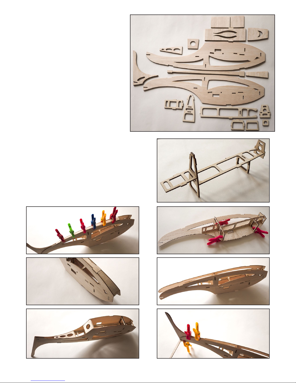
Body
A
1. Collect all parts for the body (g. A).
2. Assemble and glue inner frame skeleton
out of six ply pieces. Note doubler piece
at front-bottom. Check t of tabs and
sand if necessary before gluing (g. B).
3. Check t of skeleton frame with left body
side, ensuring all tabs t into their proper
slots, and glue in place (g. C).
4. Check t of right body side and glue in
place (g. D).
5. Check t then glue rudder post to
rear body sides. Note rudder post is
sandwiched in-between body sides. Be
sure body is square and straight before
gluing. Small clamps can help to set
alignment before gluing, and a scrap of
1/8” balsa can be used to align stabilizer slots (g. E).
6. Slide “backbone” into open top of body, check t,
sand if necessary and glue in place. Small clamps
can help ensure a solid bond (g. F).
B
7. Check t then glue top head piece. Sand if necessary
for a good t (g. G).
8. Check t then glue lower tail stiffener pieces. Sand if
necessary for a good t (g. H).
F
G
H
C
D
Copyright © 2012 Ron Marston all rights reserved rev. D 7/12
E
2
 Loading...