

Page 1
PT Coupling Co.
Safety:
a manner not intended.
Rolite PT3 Coupling Inserter & Remover
Operator’s Manual
∗ Warning: Use eye protection when working around equipment, com pr es sed ai r
Preparation:
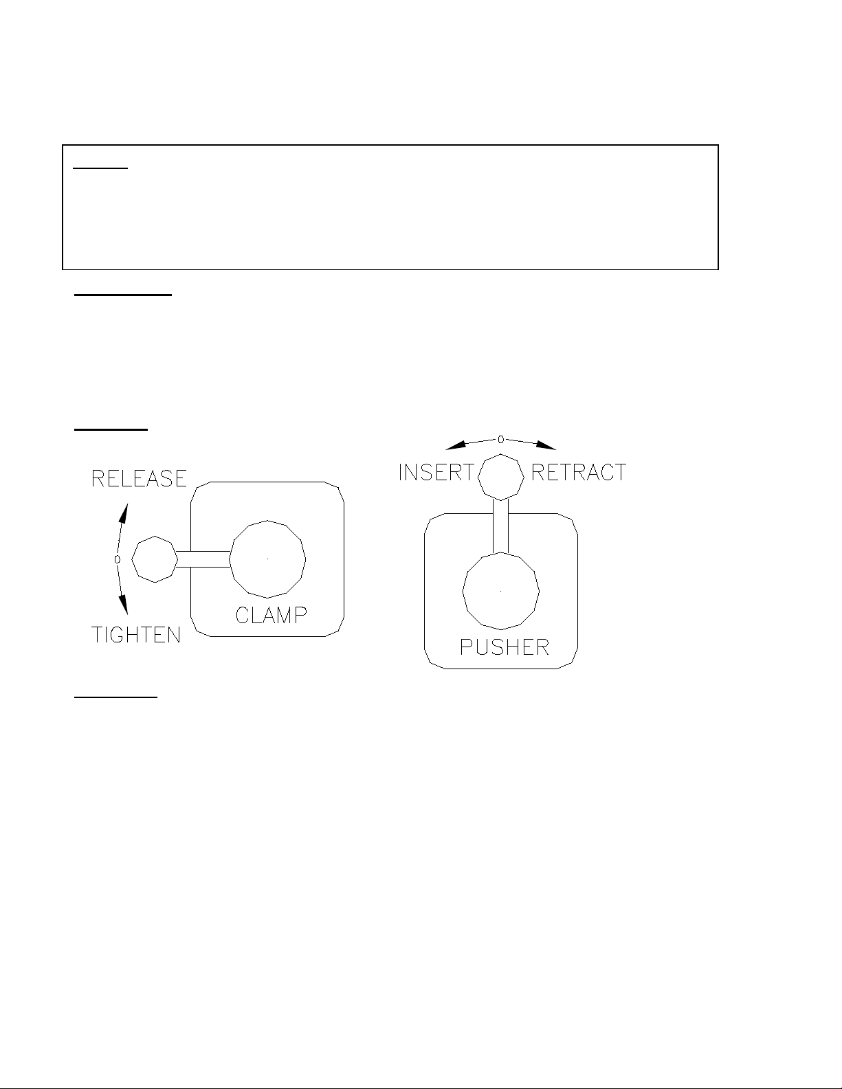
Controls:
can cause injuries.
∗ Warning: Equipment has moving parts; use care when operating equipment.
∗ Caution: Never use equipment for other than inserting & removing fittings or in
∗ The Rolite unit is not equipped with a pressure regulator. Air supply pressure will affect
the capability of the unit to proper l y insert fittings. The unit should be supplied with clean
dry lubricated compressed air between 100 to 150 psi.
∗ The Rolite unit is made of heavy materials. It is designed to provide a sturdy work
platform. When using large diameter hoses, 6” and up, it is recommended that you use
caution when inserting and removing hose from the unit.
Operation:
∗ Warning: Always return controls to neutral (center) position prior to connecting air
supply, unexpected moving parts can injure, stay clear.
1.01 Connect the air supply.
∗ Notice: All controls are proportional. The slower you move them the slower the actuated
part moves. Always move the controls slowly to maintain maximum control.
1.02 Move the belt clamp control to release position.
1.03 Release the belt hold down bar located to the left of the unit controls.
1.04 Create enough slack to insert the hose through the belt loop on top of the rollers.
1.05 Place clamps or bands if necessary on the hose and slide them down 18” onto the hose.
1.06 Insert the hose through the belt so that the end to be coupled extends 2 to 4” past the
belt.
1.07 Manually adjust the belt so that the hose and installed coupling/fitting will freely slide thru
the opening with the clamp control in the fully released position.
∗ Notice: The belt clamp mechanism will remove approximately 9” of slack from the
system.
1.08 Tighten the clamp down bar by rotating the handles against the bar.
REV. 7/12/15
Page 2

∗ Warning: Moving parts can injure, make sure hands are not near belt at this time.
1.09 Move belt clamp control to tighten position.
1.10 The cylinders will tighten the belt around the hose.
1.11 If the hose is not securely held return the control to release p os i ti on and re tur n to st ep
1.07.
1.12 Place the fitting to be pushed into the hose and secure by pushing partially into hose.
1.13 Using the hand wheel located on top of the pusher slide, raise or lower the pusher plate
to align with the fitting.
∗ Warning: Moving parts can injure, make sure hands are not near the fitting or pusher
plate at this time.
1.14 Slowly move the pusher control to insert position, watching to assure the fitting pushes
evenly into the hose.
∗ Notice: In the event that the fitting contacts the belt holding block prior to full insertion,
repeat the hose holding and insertion sequence. You may wish to reposition the hose
further through the belt and continue.
1.15 Once the fitting is fully inserted return the pusher control to neutral (center) position, then
retract the plate fully by moving the pusher control to retract position.
1.16 When the plate is fully retracted return the pusher control to ne utr al (c enter ) position.
1.17 Move the belt clamp control to release position and remove the hose and fitting from the
unit to complete the coupling process.
1.18 For additional hoses return to step 1.05.
REV. 7/12/15
 Loading...