

PTC® INSTRUMENTS
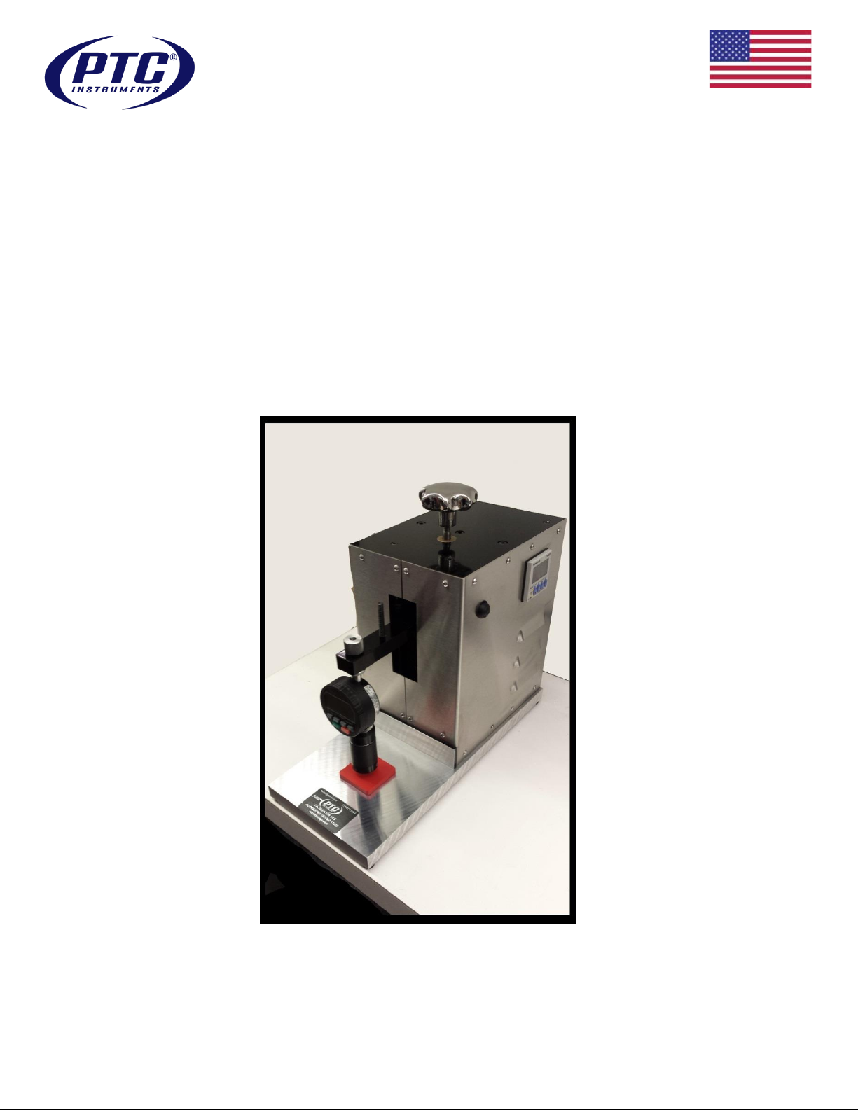
Model 500 Automatic Operating Stand Type 3
The Model 500 automatic operating stand provides constant load, controlled rate-of-descent,
and application velocity, through a geared electric motor and braking mechanism that alternately
lowers the durometer onto the specimen and then raises it in preparation for the next testing
cycle.
The electronic timer adjusts the amount of time the durometer remains in the lowered position
(dwell time), allowing time recording of test determinations. The stand can perform high volume
testing compared to hand-held or manually operated stands.
The versatile Model 500 is compatible with all PTC® 300 (Classic) and 400 (Ergo) series
durometers and most other top mounted durometers, An optional mounting adapter is required
for the PTC® (Pencil) 200 and (e2000) 500 series.
Model 500 Automatic Operating Stand
Find Quality Products Online at: sales@GlobalTestSupply.com
Model 500 Automatic Operating Stand Operating Manual
www.GlobalTestSupply.com
Page 1 of 5
Revision 4.0 5/2015

PTC® INSTRUMENTS
Model 500 Automatic Operating Stand Type 3
Specification
Description | Value
Accommodates these durometer
scales (both analog and digital):
Polymeric Knob OO, OOO, & OOO-S
Metal Knob A, B, E, & O
Additional Mass: C, D, & DO
Overall Dimensions (D x W x H):
356 x 156 x 248 mm (14 x 6.125 x 9.75 in.)
Specimen Table Dimensions:
177 x 182 mm (7 x 6 in.)
Throat Depth:
83 mm (3.25 in.)
Throat Height:
79 mm (3.125 in.)
Weight (without additional mass)
16 kg (35 lb.)
Minimum Specimen Thickness
6 mm (0.240 in.) per ASTM D2240
Maximum Specimen Thickness
varies with durometer model; ~75 mm (3 in.)
Timer Operation
0 through 9999 seconds
Power Requirements
120 VAC 60 Hz | 240 VAC 50 Hz optional
Operating Temperature
23.0 ± 2.0 °C (73.4 ± 3.6 °F)
FEATURES:
Precision machined aluminum frame provides strength, weight savings, and corrosion
resistance;
Precision machined aluminum base provides a stable, lightweight platform;
Gloss black hybrid powder coated aluminum base, top plate, and specimen platform
provide ease-of-maintenance, durability, and superior service life;
High quality, heavy duty, electric drive motor and servos provide smooth, reliable, long-
term maintenance-free operation;
Dual, precision ground, stainless steel guide rods provide the durometer support arm
and carriage assembly with the most accurate, precise, and stable application of the
durometer of any operating stand;
Dual, precision, long-reach, linear bearings allow for smooth, positive, wobble free,
operational motion;
Durometer mounting device is designed with dual conical spacers to allow for squaring
the durometer to the specimen platform to assure accurate and precise test
determinations;
Additional optional mass allow for the use of this operating stand with all ASTM D2240,
ISO 7619-1, and DIN 53 505 durometers except Type M (micro);
Stainless steel housing provides ease-of-maintenance, durability, corrosion resistance,
and industrial grade service life.
Model 500 Specifications
Find Quality Products Online at: sales@GlobalTestSupply.com
Model 500 Automatic Operating Stand Operating Manual
www.GlobalTestSupply.com
Page 2 of 5
Revision 4.0 5/2015
PTC® INSTRUMENTS
Model 500 Automatic Operating Stand Type 3
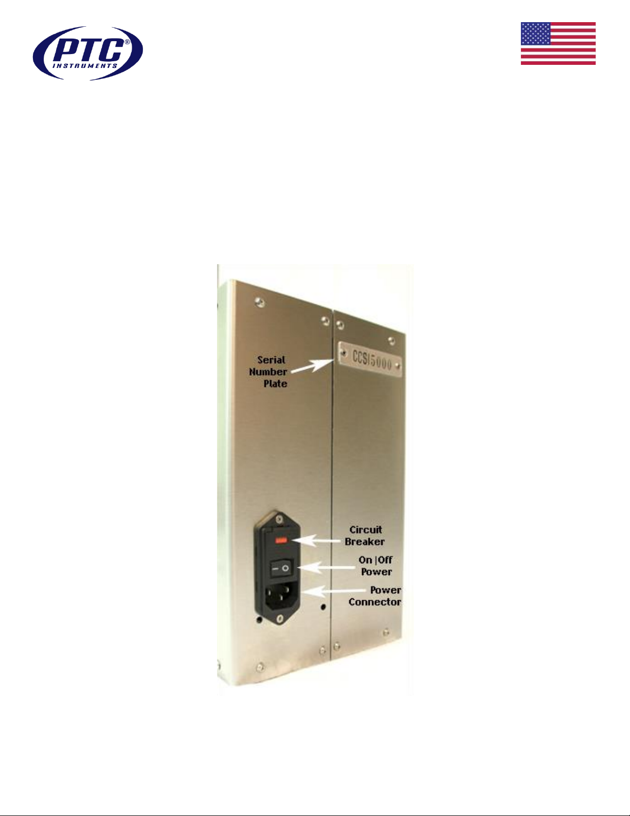
Components and Controls – Rear View
The following diagram shows the components and controls on the rear of the Model 500
automatic operating stand.
Fig. 2. Main Components and Controls of the Model 500 – Rear View
Find Quality Products Online at: sales@GlobalTestSupply.com
Model 500 Automatic Operating Stand Operating Manual
www.GlobalTestSupply.com
Page 3 of 5
Revision 4.0 5/2015

PTC® INSTRUMENTS
Model 500 Automatic Operating Stand Type 3
Mounting Instructions Pencil Style
Remove the set screws from the front mounting bracket. Place the durometer in the rear of the
mounting bracket. Position the durometer in the lowest position, mounting bracket just under the
digital head. Replace the front of the bracket and screws. Snug the set screws with the hex key
just enough to prevent slipping.
Place 2” diameter leveling block between the base of the Test Stand and the presser foot of the
durometer.
Loosen the knob on the mounting adapter holding the durometer in alignment. Maneuver the
durometer by pivoting gently left/right and forward /back mounting assembly, to ensure that the
presser foot is flush with and parallel to the block. Firmly, but gently, tighten the durometer
mounting knob. Run the test stand to the down position to be sure the durometer is now parallel
on the leveling block with the base plate. The durometer when fully engaged should read 98 to
100 on the dial indicator.
Remove the leveling block. The unit is now ready to test.
Performing ASTM D2240 Test Determinations
Turn the power switch to the ‘on’ (I is depressed) position (Fig. 2);
When the durometer mounting arm reaches the highest position (up delay), turn the power
switch off (O is depressed);
Turn the durometer height knob until the bottom of the durometer is approximately one inch
above the specimen;
Turn the power switch on. When the durometer reaches its lowest position (down delay), turn
the power switch off or use the cycle switch (Fig. 3) to halt the movement;
If needed, adjust the durometer mounting knob and durometer height knob to ensure positive
contact with the specimen;
Turn the power switch on. The Model 500 raises the durometer to the up (delay) position
The dwell timer (Fig. 3) on the side of the Model 500 controls how long the durometer remains
at the lowermost position (0 to 999 s), in contact with the specimen before returning to the
uppermost position.
Adjust the dwell timer to meet your testing requirements.
ASTM D2240 specifies a 1s dwell time, however this maybe adjusted to meet other
requirements and reported;
When the durometer returns to the uppermost position it will begin the next test cycle by
actuating the cycle switch located on the side of the 500;
Record each reading for at least five cycles;
When employing a durometer with an analogue maximum indicating hand or digital maximum
reading hold feature, reset it at each up delay cycle;
Find Quality Products Online at: sales@GlobalTestSupply.com
Model 500 Automatic Operating Stand Operating Manual
www.GlobalTestSupply.com
Page 4 of 5
Revision 4.0 5/2015

PTC® INSTRUMENTS
Model 500 Automatic Operating Stand Type 3
Calculate the average or the mean (refer to ASTM D2240) of the readings to obtain the test
result.
CAUTION
Turn off (cycle switch or power switch) the Model 500 only when it is in the up delay or down
delay position. If the Model 500 is turned off while the stand is in motion, it may stall the motor.
If the motor stalls or slows severely, remove any optional mass, turn the power switch off and on, then
use the cycle switch to halt/resume travel until the normal cycle resumes. This may take several
repetitions.
Find Quality Products Online at: sales@GlobalTestSupply.com
Model 500 Automatic Operating Stand Operating Manual
www.GlobalTestSupply.com
Page 5 of 5
Revision 4.0 5/2015
 Loading...