

PTAC WALL SLEEVE Installation Instructions Manual
PTAC
W
INSTALLATION INSTRUCTIONS
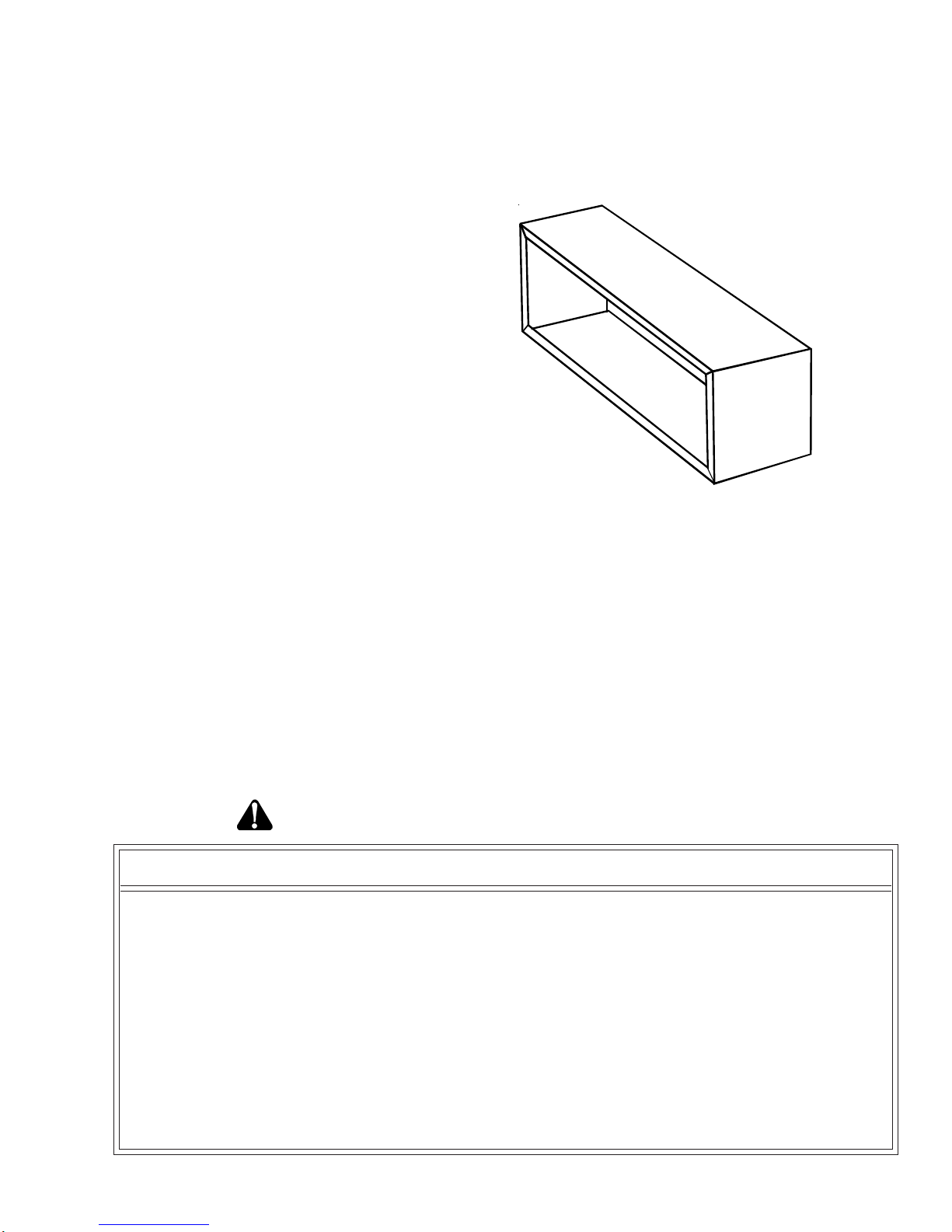
The wall sleeve must be installed before the air conditioner or heat pump chassis can be
set in place. Read the instructions thoroughly before proceeding.
When 230/208 volt units are to be installed, the power
supply may be either cord connected or permanent
wiring. Permanent wiring may be done through the hard
wire junction box, or the accessory subbase.
When 265 volt units are to be installed, the power supply
must be permanent wiring. Permanent wiring may be
done through the accessory hard wire junction box, or
the accessory subbase. An exposed cord connection
on 265 volt units is not permitted.
The subbase accessory includes leveling legs. If added
wall sleeve support is required and the subbase is not to
be used an accessory leveling leg kit may be installed.
ALL
S
LEEVE
Made in USA
Contents
KIT ACCESSORIES .....................................................................................................2
DRAIN KIT ....................................................................................................... 2
SUBBASE, LEVELING LEGS, MAIN DUCT, AND HYDRONIC HEAT KITS ........................ 2
PRE-INST ALLA TION CONSIDERA TIONS .................................................................. 3
OUTDOOR ENCLOSURE PANEL REMOVAL.............................................................. 3
WALL SLEEVE INST ALLA TION.................................................................................. 4
RECOGNIZE THIS SYMBOL AS A SAFETY PRECAUTION
ATTENTION INSTALLING PERSONNEL
As a professional installer you have an obligation to know the product better than the customer. This
includes all safety precautions and related items.
Prior to actual installation, thoroughly familiarize yourself with this Instruction Manual. Pay special
attention to all safety warnings. Often during installation or repair it is possible to place yourself in a
position which is more hazardous than when the unit is in operation.
Remember, it is your responsibility to install the product safely and to know it well enough to be able to
instruct a customer in its safe use.
Safety is a matter of common sense...a matter of thinking before acting. Most dealers have a list of
specific good safety practices...follow them.
The precautions listed in this Installation Manual are intended as supplemental to existing practices.
However, if there is a direct conflict between existing practices and the content of this manual, the
precautions listed here take precedence.
Part No. A3495105
Printed in USA
August 2005

KIT ACCESSORIES
DRAIN KIT
An indoor/outdoor drain kit is available as an accessory
item. When a drain kit is to be installed, do so before
installing the wall sleeve in the wall. See the drain kit for
actual installation instructions.
SUBBASE, LEVELING LEGS, MAIN DUCT, AND
HYDRONIC HEAT KITS
Installation of these kits requires drilling of mounting
holes on both sides of the wall sleeve. The minimum
required clearance distance between the wall sleeve and
wall is shown in Table 1. If the distance between wall
sleeve and wall will be at or near the minimum clearance
distance, mount these kits on the sleeve before installing
the sleeve in the wall. The kit installation instructions are
included with the accessory kits.
1
6
1
/
1
6
"
4
1
0
m
m
4
2
"
1
0
6
5
m
m
4
2
1
1
0
/
4
7
"
M
5
i
m
n
m
i
m
u
m
m
"
m
4
u
/
m
1
m
i
5
6
n
1
i
1
4
M
Finished Floor
Dimension "B"
in Table 1
Figure 2 - Minimum Wall Opening Dimensions
Outside
Wall
Top of Wall Sleeve
Internal
Adjacent
Wall
"A"
Minimum
"A"
Minimum
Allow Front Clearance (See Table 1)
Internal
Adjacent
Wall
1
4
1
/
8
"
3
5
9
m
m
Wall Receptacle Within 58" From
Bottom Right Side Corner on
208/230 VAC Units Only
Figure 1 - Wall Sleeve Dimensions
Figure 3 - Minimum Unit Clearances
Room
Side
"C" in
Table 1
"B" in
Table 1
Carpet or
Finished Floor
Cabinet
Side
1/4"
6 mm
Minimum
Outside
Wall
Figure 4 - Minimum Interior and Exterior
MINIMUM CLEARANCES AND PROJECTIONS
MINIMUM CLEARANCES MINIMUM PROJECTION
OPTION
C (Figure 4)B (Figure 3)A (Figure 2)
Inches mm Inches mm Inches mm
Wall Sleeve Only 3750 0 0 0
Subbase Kit 3 75 3 1/4 85 2 3/4 70
Leveling Legs Kit 3 75 3 75 2 50
Duct Kit 3 75 0 0 2 3/8 35
Hydronic Heat Kit "A Series" 9 230
0 to 3 1/4
3
0 to 85
3
2
3
75
2
Hydronic Heat Kit "J Series" 6 150 0 0 2 1/2 65
Drain Kit 3 75
'0
1
'0
1
00
Hardwire Kit 3 75 1 1/4 30 0 0
1
If inside mounted then B = 1 1/2 inches (40 mm)
2
To achieve a flush fit between the hydronic front and the finished wall, Dimension “C” must be between 3” and
3 1/8”. If this dimension is more than 3 1/8” there will be a gap between the front and the wall. This gap could
permit occupant access to hydronic lines or other dangerous parts.
3
This dimension can be from 0” to 3-1/4”, but cannot exceed 3-1/4”. If this dimension exceeds 3-1/4”, the skirt
around the front will not reach the floor.
Table 1
2
 Loading...