

Page 1

Page 2

Copyright
All Rights Reserved. No part of this document may be copied,
reproduced, republished, uploaded, posted, transmitted,
distributed, stored in or introduced into a retrieval system in
any form, or by any means (electronic, mechanical,
photocopying, recording or otherwise) whatsoever without
prior written permission of PT Ltd.
Disclaimer
PT Ltd reserves the right to make changes to the products
contained in this manual in order to improve design,
performance or reliability.
The information in this manual is believed to be accurate in all
respects at the time of publication, but is subject to change
without notice. PT Ltd assumes no responsibility for any errors
or omissions and disclaims responsibility for any consequences
resulting from the use of the information provided herein.
SPECIAL NOTE
Trade Use of the PT200 Series
This manual may occasionally make reference to Trade Use
settings of the PT200 Series.
Some individual settings may not be legal for trade use.
Please check regulations with the appropriate Weights and
Measures Authority.
Page 3

Reference Manual Rev 1.0
Table of Contents
1. INTRODUCTION ....................................................................................................................3
1.1. Overview .....................................................................................................................3
1.2. Approvals (for trade versions only) .............................................................................3
1.3. The Manuals Set.........................................................................................................4
1.4. Document Conventions...............................................................................................4
2. SPECIFICATIONS..................................................................................................................5
3. INSTALLATION ..................................................................................................................... 6
3.1. Introduction ................................................................................................................. 6
3.2. General Warnings .......................................................................................................6
3.3. Electrical Safety ..........................................................................................................6
3.4. Cleaning ......................................................................................................................6
3.5. Panel Mount Template ................................................................................................6
3.6. Cable Connections......................................................................................................7
3.7. DC Power (DC PWR + , DC PWR –) ......................................................................... 7
3.8. Load Cell Connection.................................................................................................. 7
3.8.1.
3.8.2.
3.8.3.
3.9. Auxiliary Connections..................................................................................................9
3.9.1.
3.9.2.
3.9.3.
3.10. opto-LINK (Optional) ................................................................................................. 12
3.11. Connecting Shields ................................................................................................... 13
3.11.1. Cable Shield Connection and Earthing.....................................................13
3.12. Regulatory Sealing Requirements ............................................................................13
4. DATA ENTRY.......................................................................................................................14
4.1. Editing Annunciators ................................................................................................. 14
4.2. Numeric Entry ...........................................................................................................15
4.3. Selections and Options ............................................................................................. 15
5. BASIC OPERATION ............................................................................................................16
5.1. Display and Controls .................................................................................................16
5.1.1.
5.2. Operation Keys .........................................................................................................17
5.2.1.
5.2.2.
5.3. Stability Considerations.............................................................................................18
5.4. POWER Key .............................................................................................................18
5.4.1.
5.5. ZERO Key .................................................................................................................18
5.6. TARE Key .................................................................................................................19
5.7. GROSS/NET Key......................................................................................................19
5.7.1.
5.8. PRINT Key ................................................................................................................20
5.9. FUNCTION Key ........................................................................................................20
6. CONFIGURATION ISSUES .................................................................................................21
6.1. General Setup Information ........................................................................................21
6.2. Basic Weighing Terminology.....................................................................................21
6.3. Filtering Techniques.................................................................................................. 22
6.4. Industrial vs OIML and NTEP Modes........................................................................22
6.5. Calibration Counter ................................................................................................... 23
6.6. Passcodes.................................................................................................................24
6.6.1.
6.6.2.
6.6.3.
7. SETUP..................................................................................................................................25
7.1. Accessing Setup .......................................................................................................25
7.1.1.
Load Cell Signals and Scale Build..............................................................7
4-Wire Connection ...................................................................................... 8
6-Wire Connection ...................................................................................... 8
RS-232 Serial..............................................................................................9
Remote Input ............................................................................................10
Outputs .....................................................................................................11
Front Panel: Visual Display....................................................................... 16
Primary Function.......................................................................................17
Editing Function ........................................................................................ 17
Automatic Operation ................................................................................. 18
opto-LINK Activation ................................................................................. 19
Full Setup Passcode.................................................................................24
Safe Setup Passcode ...............................................................................24
Setup Lock-Out .........................................................................................24
Setup Display Prompts .............................................................................26
003R-618-100 Page 1
Page 4

Reference Manual Rev 1.0
7.2. Exiting Full or Safe Setup..........................................................................................26
7.3. Groups and Items......................................................................................................26
7.3.1.
7.3.2.
7.4. Setup Menus .............................................................................................................27
7.4.1.
7.4.2.
7.4.3.
7.4.4.
7.4.5.
7.4.6.
7.4.7.
7.4.8.
7.4.9.
7.4.10. – End – (Leaving Setup) ........................................................................... 35
8. CALIBRATION .....................................................................................................................36
8.1. Performing a Digital Calibration with Test Weights ...................................................36
8.1.1.
8.1.2.
8.2. Performing a Calibration with Direct mV/V Entry ......................................................37
8.2.1.
8.2.2.
8.3. Using Linearisation....................................................................................................38
8.3.1.
8.3.2.
9. SERIAL OUTPUTS ..............................................................................................................40
9.1. Automatic Weight Output ..........................................................................................40
9.2. Master Serial Output .................................................................................................41
10. SETPOINTS .........................................................................................................................42
10.1. Setpoint Connection.................................................................................................. 42
10.2. Setpoint Operation .................................................................................................... 42
11. SPECIAL FUNCTIONS ........................................................................................................43
11.1. Introduction ............................................................................................................... 43
11.2. Key Functions ...........................................................................................................43
11.2.1. NONE........................................................................................................43
11.2.2. TEST......................................................................................................... 43
11.2.3. COUNT .....................................................................................................43
11.2.4. UNITS ....................................................................................................... 43
11.2.5. HOLD and PEAK HOLD ...........................................................................44
11.2.6. LIVE.WT....................................................................................................44
11.2.7. SHOW.T....................................................................................................45
12. APPENDIX ........................................................................................................................... 46
12.1. Dimensions ...............................................................................................................46
12.2. Sealing Details .......................................................................................................... 47
12.3. Setup Menu Quick Reference ...................................................................................48
12.4. Error Messages.........................................................................................................49
12.4.1. Weighing Errors ........................................................................................ 49
12.4.2. Setup and Calibration Errors.....................................................................50
12.5. Diagnostic Errors.......................................................................................................51
12.6. Glossary Terms.........................................................................................................52
12.7. List of Figures............................................................................................................52
12.8. List of Tables............................................................................................................. 52
13. INDEX...................................................................................................................................53
GRP (Group).............................................................................................26
ITM (Item) .................................................................................................27
BUILD (Scale Build) ..................................................................................27
OPTION (Scale Options) ..........................................................................28
CAL (Scale Calibration) ............................................................................29
SPEC (Special Settings Menu) .................................................................30
SERIAL (Serial Communications Options) ...............................................32
SET.PTS (Setpoint Settings) ....................................................................33
CLOCK (Clock Settings) ...........................................................................34
TEST (Special Test Functions).................................................................34
FACTRY (Factory Adjustment Menu) .......................................................35
ZERO (Zero Calibration Routine)..............................................................37
SPAN (Span Calibration Routine).............................................................37
DIR.ZER (Direct Zero Calibration Entry)...................................................37
DIR.SPN (Direct Span Calibration Entry)..................................................38
ED.LIN (Edit Linearisation Points) ............................................................39
CLR.LIN (Clear Linearisation)...................................................................39
Page 2 003R-618-100
Page 5
Reference Manual Rev 1.0
1. Introduction
This instrument is a precision digital indicator using the latest Sigma-Delta A/D technology
to ensure fast and accurate weight readings.
The setup and calibration of the instrument are digital, with a non-volatile security store for
all setup parameters.
The instrument may be operated from either 4 AA batteries or a DC power source from
12V to 24V. There is a soft power on/off function that retains memory of its state. Once
an instrument is turned on it will automatically start up again if the external power is
interrupted.
The instrument is fitted with opto-LINK communications as standard. This allows a
temporary isolated communications link to be established with a PC and enables software
upgrades and the use of computerised setup and calibration via the Viewer software.
Refer to opto-LINK (Optional) page 12 for more information.
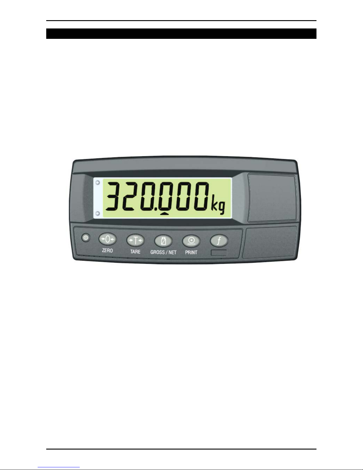
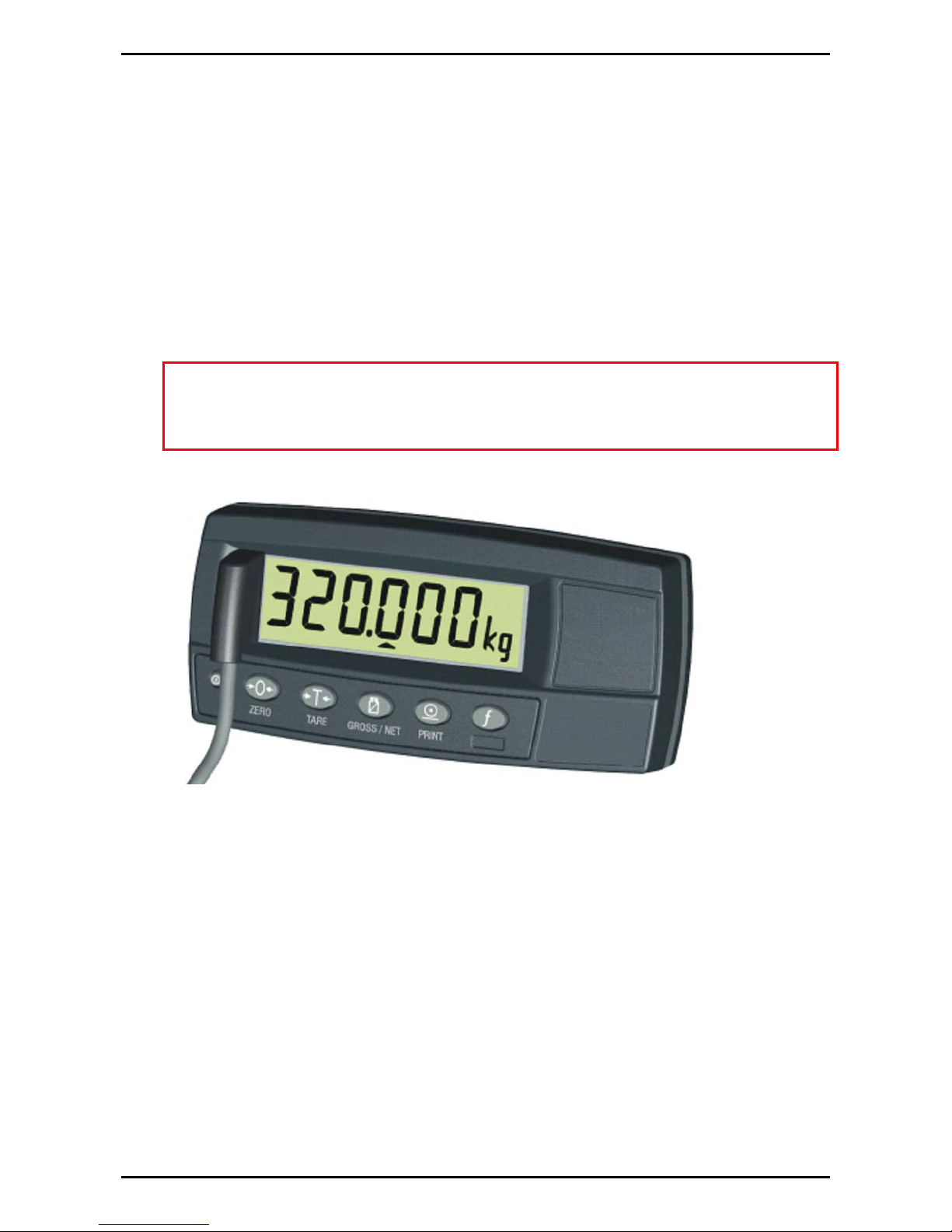
Figure 1: Weight Indicator
1.1. Overview
This instrument provides the
ZERO
more setup options (eg. serial and setpoints) and printing functionality.
It also supports special functions (eg. peak-hold, live weight (livestock) averaging,
counting, etc.), via the user definable
NVRAM store to ensure day-to-day operating settings (eg.
etc.), are retained when power is removed.
This instrument has two isolated transistor outputs with status display on the front
panel as well as the RS-232 communications port that can be used for printer
driving or connection to a remote display or PC. There is a built-in clock for datestamping printed outputs.
1.2. Approvals (for trade versions only)
•
NSC approval (4000 divisions at 0.8µV/division).
• NMI approval (4000 divisions at 0.8µV/division).
•
C-tick approved and CE approved.
TARE
and
<FUNCTION>
functionality as well as providing
key. It is equipped with an
ZERO, TARE, CLOCK
,
003R-618-100 Page 3
Page 6

Reference Manual Rev 1.0
1.3. The Manuals Set
This manual is part of a set of manuals covering the setup and operation of the
instrument. The set includes the following:
• Reference Manual - Contains detailed information on calibration and setup.
This manual is intended for use by Scale Technicians who are installing the
instrument.
• Operator Manual
- Aimed at the operation of the instrument, and covers the
day-to-day operation of the instrument.
• Quick Start Manual
- Intended for Scale Technicians who are familiar with the
instrument and simply need a quick reference to menu options and connection
diagrams, etc.
• Communications Manual
capabilities (communications protocol).
1.4. Document Conventions
The following document conventions (typographical) are used throughout this
Reference Manual.
- Contains details on the extended networking
Bold Text
Bold text denotes words and phrases to note.
<Key> <Key>
Note:
than
and the > symbol means
^
This symbol denotes one space (used in Automatic Weight
Output page 40)
⊗
Items marked with ⊗ indicate that the setting is available only in
Full Setup and is trade critical. When trade critical settings are
changed the calibration counter will be incremented.
denotes a Keypad key.
In the Specifications section the < symbol means
greater than
.
less
Page 4 003R-618-100
Page 7
Reference Manual Rev 1.0
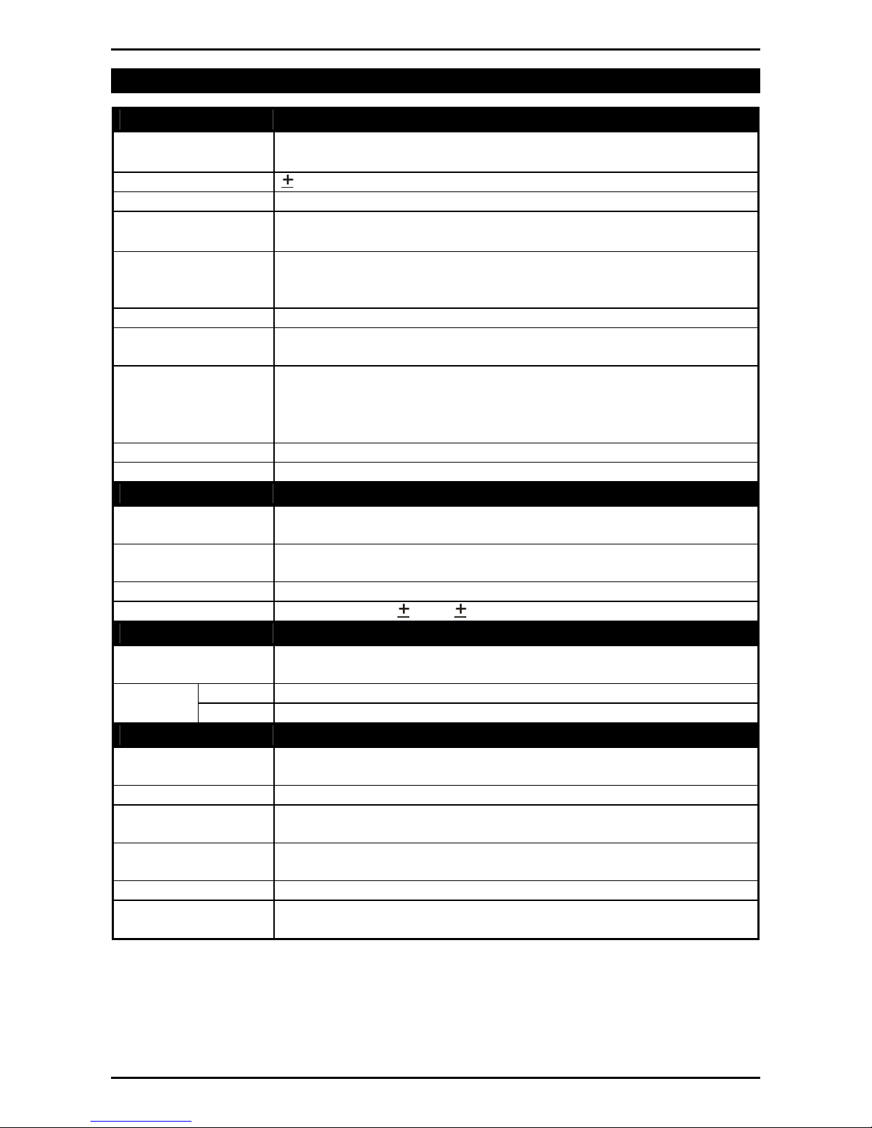
2. Specifications
Performance
Resolution
Zero Cancellation
Span Adjustment 0.1mV/V to 3.0mV/V full scale
Stability/Drift
Excitation 5 volts for up to 4 x 350 or 8 x 700 ohm load cells (4-wire or 6-
A/D Type 24bit Sigma Delta with 8,388,608 internal counts
A/D Conversion
Rate
Operating
Environment
Case Materials ABS, Silicon Rubber, Nylon, Acrylic (no halogen used)
Packing Weights Basic Indicator: 0.34kg
Digital
Display LED Backlit LCD with six 20mm high digits with units and
Setup and
Calibration
Digital Filter Sliding window average from 0.1 to 4.0 seconds
Zero Range Adjustable from 2% to 20% of full capacity
Power Input
Standard Power
Input
Variants AC AC Plug pack: 110/240VAC 50/60Hz in 12VDC 0.5A out
Battery 4 x AA batteries (Alkaline or rechargeable NiMH, NiCad, etc.)
Features
opto-LINK Data
Coupling
Correction Five point linearity correction
Outputs RS-232 automatic transmit, network or printer outputs.
Assignable Function
Key
Drive Outputs 2 isolated transistor drive outputs (300mA total at 50VDC)
Battery Backed
Clock Calendar
Up to 30,000 divisions, minimum of 0.25µV/division, 20
updates/second (Trade 4000 divisions at 0.8µV/division)
2.0mV/V
Zero: < 0.1µV/°C (+ 8ppm of deadload max)
Span < 8 ppm/°C, Linearity < 20ppm, Noise < 0.2µVp-p
wire plus shield)
Maximum total load cell resistance: 1,000 ohms
20Hz with FIR filtering > 80dB
Temperature: –10 to +50°C ambient
Humidity: <90% non-condensing
Storage: –20 to +50°C ambient
IP55 when panel mounted
annunciators
Full digital with visual prompting in plain messages
12 to 24VDC (2.5 VA max) - ON/OFF key with memory feature
Infra-red Connector for optional opto-LINK PC cable (to RS-232
PC port)
Transmission rate: 2400, 4800 or 9600 baud
Unit switching, counting, manual hold, peak hold, live weight and
totalising
Battery life 10 years minimum
003R-618-100 Page 5
Page 8

3.1. Introduction
The following steps are required to set up the indicator.
•
Inspect indicator to ensure good condition.
•
Use connection diagrams to wire up load cell, power and auxiliary cables as
required.
• Use the drill hole template provided for hole locations.
•
Connect Power to indicator and press
• Refer to the Setup section page 25 for information on configuring and calibrating
the instrument.
• To turn instrument Off press and hold <POWER> key for three seconds (until
display blanks).
3.2. General Warnings
•
Indicator not to be subject to shock, excessive vibration or extremes of
temperature (before or after installation).
• Inputs are protected against electrical interference, but excessive levels of
electro-magnetic radiation and RFI may affect the accuracy and stability.
• The instrument should be installed away from any sources of excessive
electrical noise.
• The load cell cable is particularly sensitive to electrical noise and should be
located well away from any power or switching circuits.
•
For full EMC or for RFI immunity, termination of cable shields and correct
earthing of the instrument is essential.
•
Indicator and load cell cable are sensitive to excessive electrical noise. Install
well away from any power or switching circuits.
Reference Manual Rev 1.0
3. Installation
<POWER>
key to turn the instrument On.
3.3. Electrical Safety
• For your protection all mains electrical hardware must be rated for environmental
conditions of use.
•
Pluggable equipment must be installed near an easily accessible power socket
outlet.
•
To avoid the possibility of electric shock or damage to the instrument, always
switch off or isolate the instrument from the power supply before maintenance is
carried out.
3.4. Cleaning
•
To maintain the instrument, never use harsh abrasive cleaners or solvents.
Wipe the instrument with a soft cloth
3.5. Panel Mount Template
Use the panel mount template for drill hole locations. The template indicates
positions for the two 4mm mounting screws through the panel. Also displayed on
the template is the position of the rectangular hole that should be cut to allow for the
connection of cables. The drilling template supplied with the indicator allows for
front or rear machining of the panel.
slightly
dampened with warm soapy water.
Page 6 003R-618-100
Page 9
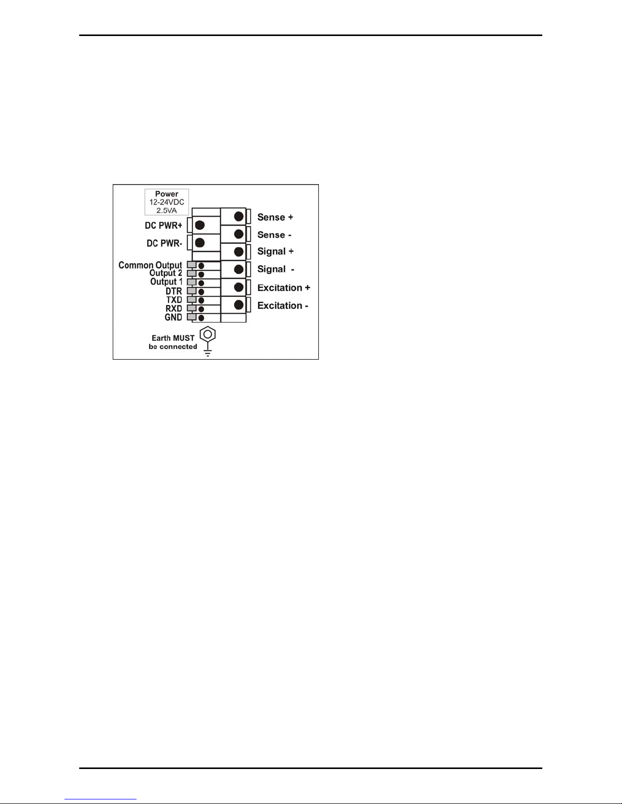
3.6. Cable Connections
All cable connections are made to the rear of the instrument using screwless
terminals. Wires must be stripped of insulation by at least 10mm. To install,
depress the orange lever beside the terminal required and push wire into the hole.
Release the lever and pull gently on the wire to ensure it is securely trapped in the
terminal. It is not necessary to tin the ends of the wire with solder or to add crimp
ferrules to the wires, however, these techniques are also compatible with the
terminals and may ultimately make for a neater job.
Reference Manual Rev 1.0
Figure 2: Cable Connections
3.7. DC Power (DC PWR + , DC PWR –)
The DC supply need not be regulated, provided that it is free of excessive electrical
noise and sudden transients. The instrument can be operated from a high quality
plug-pack as long as there is sufficient capacity to drive both it and the load cells.
3.8. Load Cell Connection
3.8.1. Load Cell Signals and Scale Build
Very low output scale bases may be used but may induce some instability in the
weight readings when used with higher resolutions. Generally speaking, the higher
the output, or the lower the number of divisions, the greater the display stability and
accuracy.
The instrument can display the milliVolt-per-Volt reading that can be used to check
scale base signal output levels. For more information, refer to SCALE (Scale Base
Test Display) page 34.
The instrument may be connected for either 4-wire or 6–wire operation. To
correspond with the actual cabling installation the instrument must be configured in
setup to the correct setting. For more information, refer to CABLE (4-Wire or 6Wire) ⊗ page 28.
003R-618-100 Page 7
Page 10
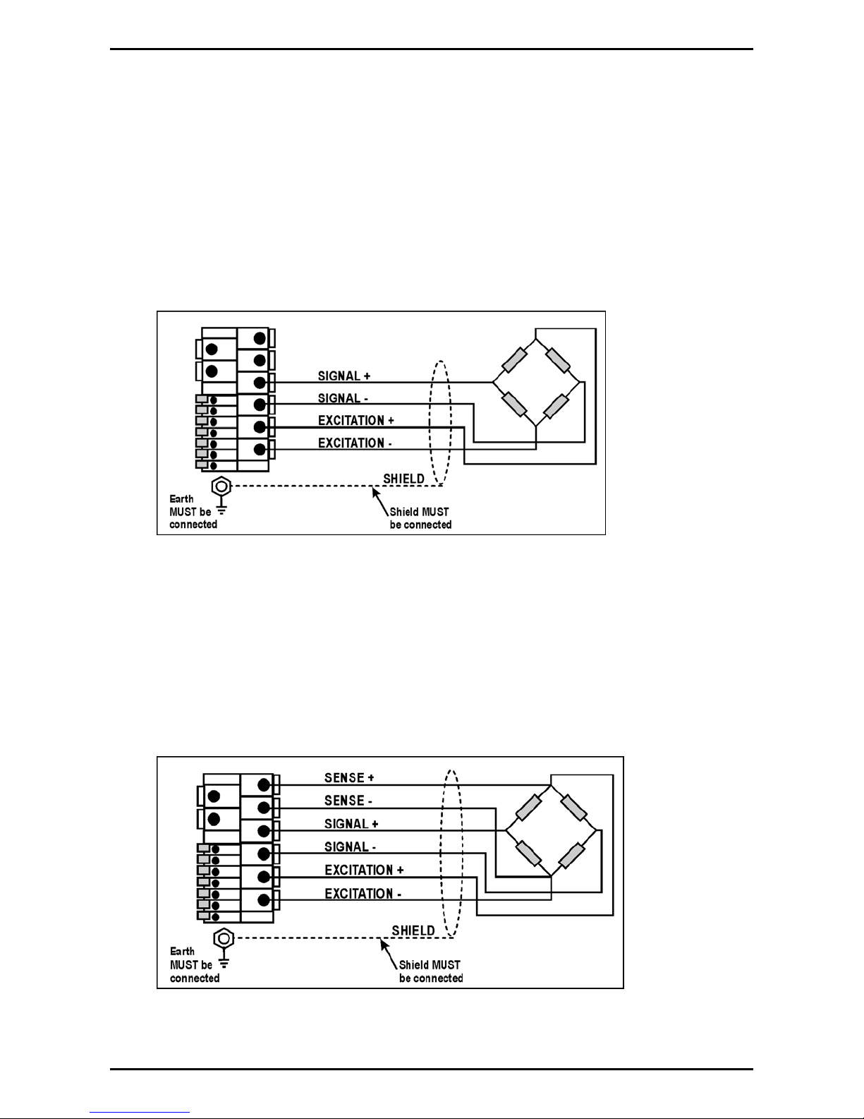
3.8.2. 4-Wire Connection
The minimum connectivity requirements are the connection of four wires (ie.
Excitation + and – along with Signal + and –). Internally the instrument has a
precision analog switch that can be used to connect the Sense + and – lines directly
to the Excitation + and – lines.
Any addition to the load cell manufacturer's cable length using 4-wire connection, is
only recommended for short cable runs. Where long additions to cable lengths are
needed, a 6-wire extension is required.
The BUILD:CABLE option must be set to 4 to allow for 4-wire connection. Refer to
CABLE (4-Wire or 6-Wire) ⊗ page 28.
Reference Manual Rev 1.0
Figure 3: 4-Wire Connections
3.8.3. 6-Wire Connection
The excitation and signal lines are connected the same as for a 4-wire installation.
The extra two wires (Sense + and –) should be connected to the Excitation + and –
lines as close as possible to the load cell itself. Typically these connections are
made in a load cell termination box.
The BUILD:CABLE option must be set to 6 (the default) to allow for 6-wire
connection. Refer to CABLE (4-Wire or 6-Wire) ⊗ page 28.
Figure 4: 6-Wire Connections
Page 8 003R-618-100
Page 11
Reference Manual Rev 1.0
3.9. Auxiliary Connections
This section provides diagrams to illustrate the terminal connections.
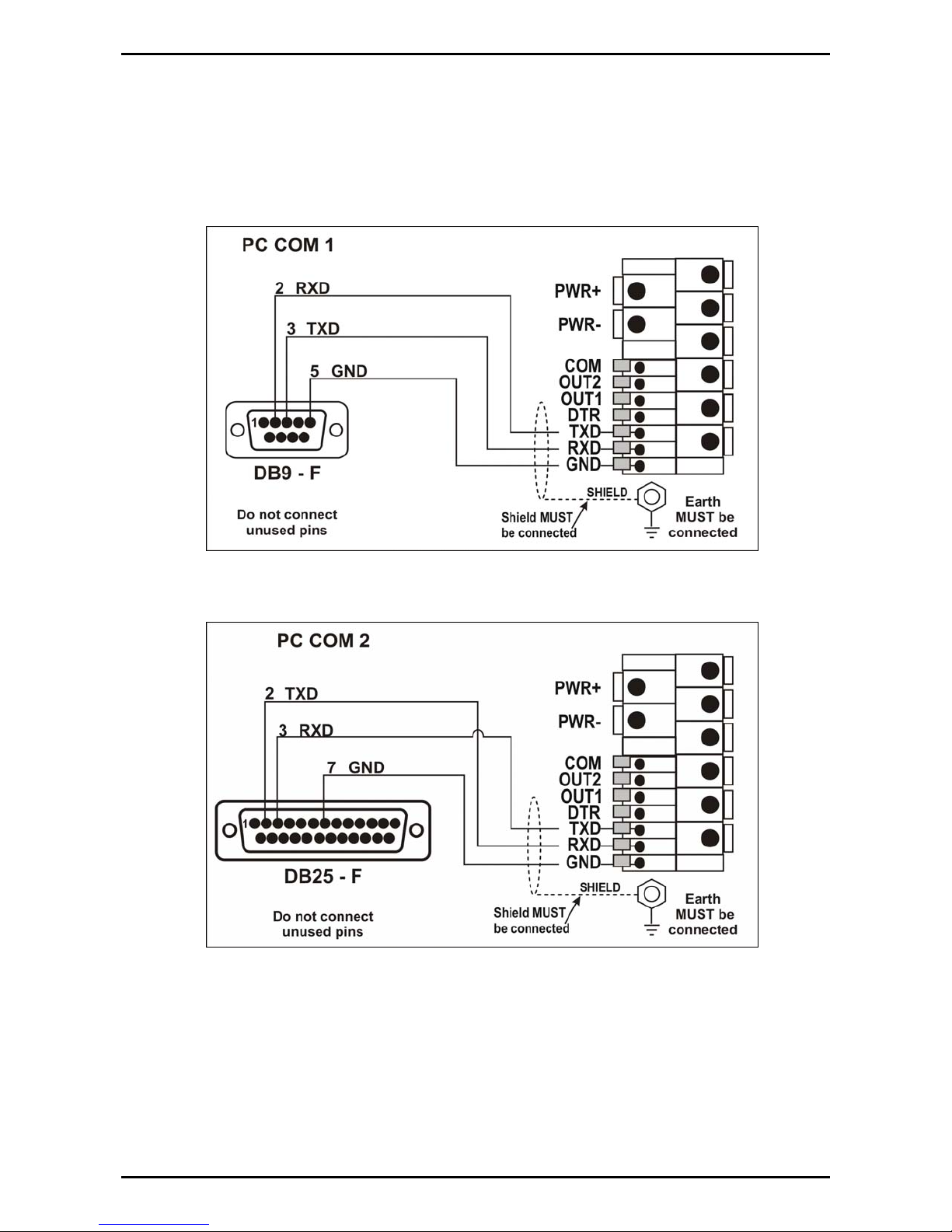
3.9.1. RS-232 Serial
• Direct Personal Computer Link (RXD, TXD, GND)
Figure 5: RS-232 - Instrument to PC using COM Port (DB9)
Figure 6: RS-232 – Instrument to PC using COM Port (DB25)
003R-618-100 Page 9
Page 12
Reference Manual Rev 1.0
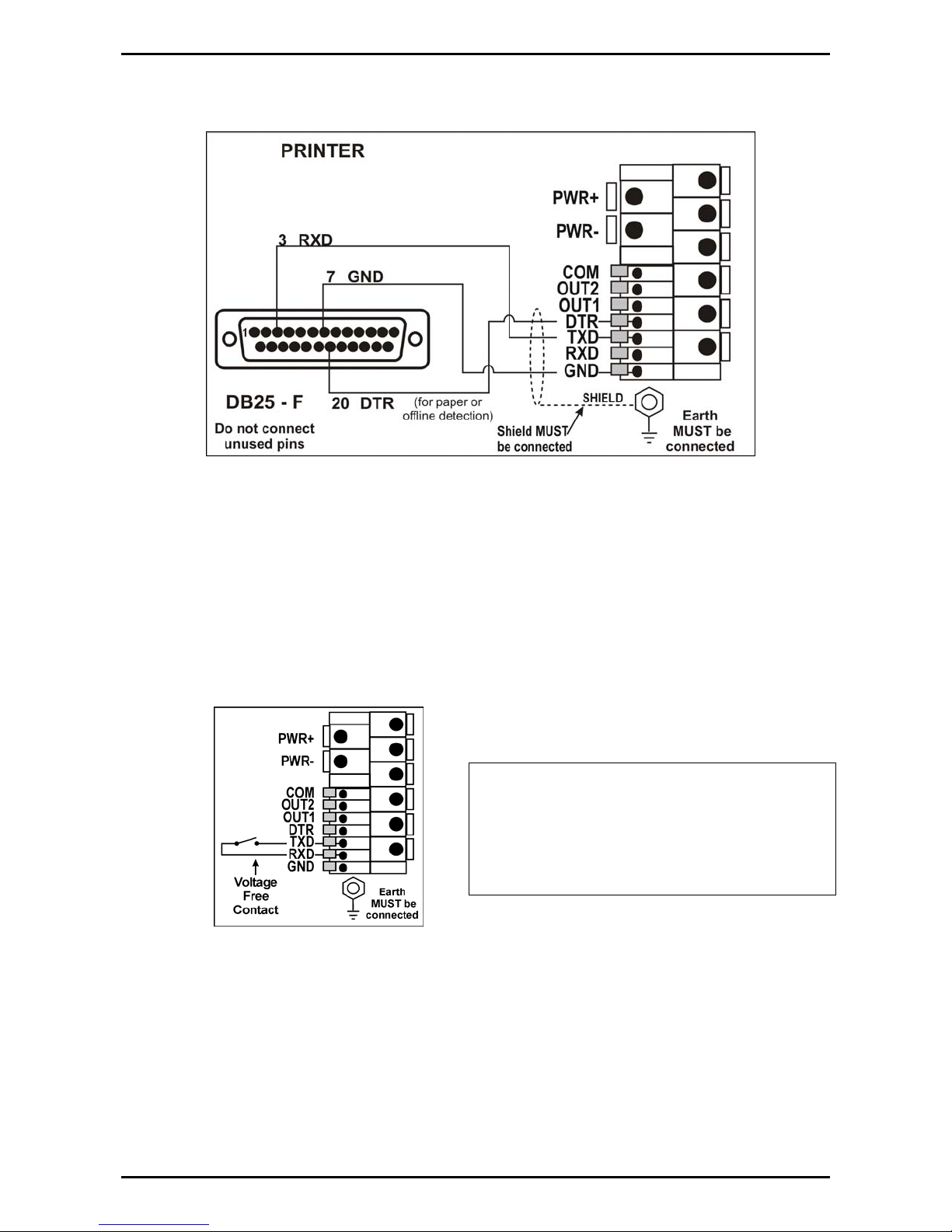
• Printer Connections (RXD/TXD, GND and DTR)
Figure 7: RS-232 – Instrument to Printer (DB25)
• Remote Display (TXD, GND)
The remote display documentation should be referred to for connection details.
Connect TXD to RXD and GND to GND on the remote display.
3.9.2. Remote Input
The indicator requires a voltage free contact between TXD and RXD to enable
the remote input (ie. SPEC:REM.FN). Note: The remote input will not function
when in setup or when using the opto-LINK.
Figure 8: Remote Input
WARNING
The remote input is a voltage free contact
(eg. button, mechanical relay).
Connection of any active circuitry may
damage the instrument.
Page 10 003R-618-100
Page 13
3.9.3. Outputs
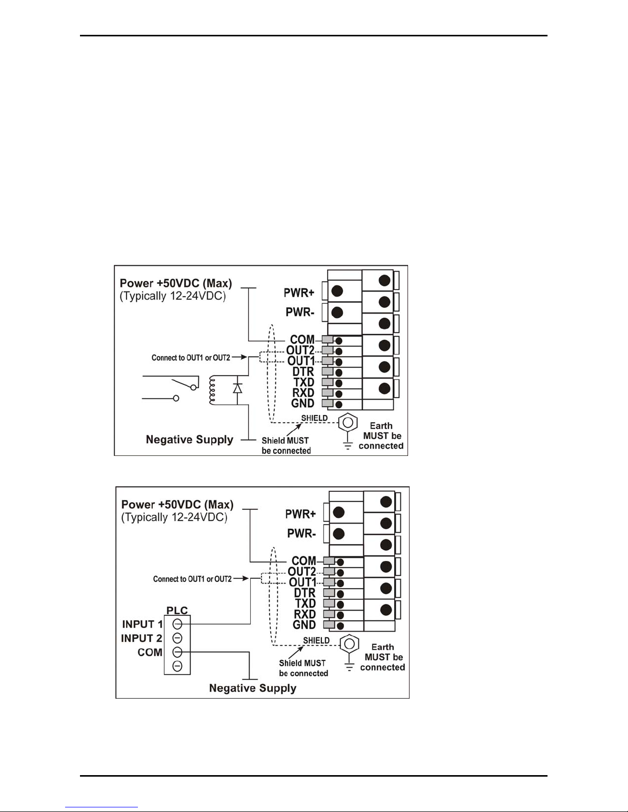
The output drivers for the instrument are isolated open emitter transistor drives that
are capable of driving up to a total of 300mA. This configuration allows for the direct
connection of the instrument outputs to most types of PLC.
The voltage applied to the COM terminal appears on the output lines (ie. OUT1 and
OUT2) when the outputs are active (eg. to connect to a PLC connect +24V to the
common terminal). The outputs can then be connected directly to PLC inputs so
when activated are active the PLC will see the 22V signal (approx. - the exact switch
loss will depend on loading of the output).
To drive external loads (eg. relays), connect the relay coil positive supply to the
output common and the output line directly to one side of the relay coil. Connect the
other end of the relay coil to the negative supply. It is recommended that fly-back
diodes or transient suppressors be fitted across relay coils to limit switching noise.
Reference Manual Rev 1.0
Figure 9: Instrument Outputs to Drive Relay
Figure 10: Instrument Outputs to Drive PLC
003R-618-100 Page 11
Page 14
3.10. opto-LINK (Optional)
A temporary infrared communications link can be established between the
instrument and a PC using an optional opto-LINK cable. The optional opto-LINK
cable can be used to transfer setup and calibration information from a PC (eg. to be
stored for later use and/or transferred to other instruments). It can also be used to
download software upgrades to the instrument from a PC.
The PC end of the opto-LINK cable is a standard female DB9 connector. The
instrument end of the cable consists of an infrared transceiver, which attaches to the
left side of the instrument display. To facilitate a quick and simple connection, the
infrared transceiver is secured in place by a permanent magnet located within the
head of the opto-LINK.
Refer to opto-LINK Activation page 19 for more information.
Reference Manual Rev 1.0
WARNING
The opto-LINK head contains a strong magnet and care should be taken with
it's proximity to electronic media (eg. credit cards, floppy disks, etc.) and/or
other electronic instrumentation.
Figure 11: opto-LINK Attachment
Page 12 003R-618-100
Page 15
3.11. Connecting Shields
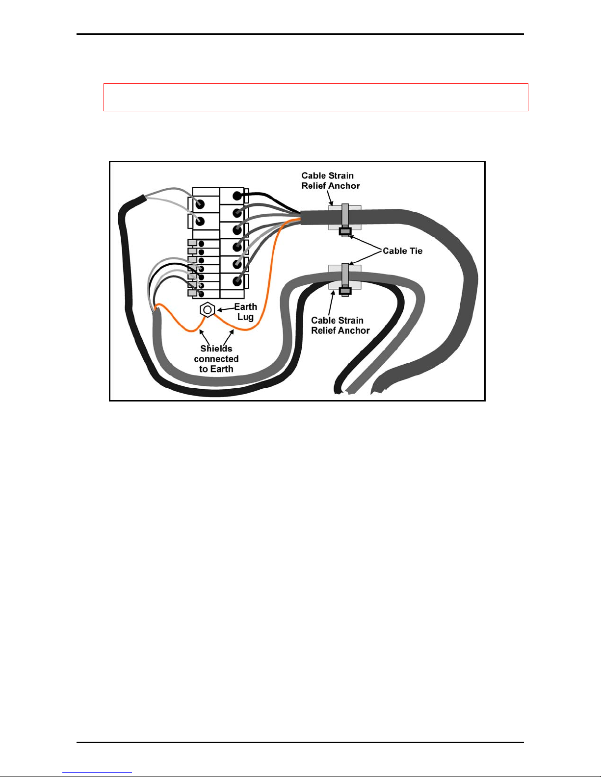
To obtain full EMC or for RFI immunity, cable shields MUST be connected to the
earth lug on the rear of the instrument.
Figure 12 illustrates an example of possible connections. Also shown are the
connecting cables restrained using cable ties fastened around the cable strain relief
anchors.
Reference Manual Rev 1.0
Figure 12: Cable Shield Connection
3.11.1. Cable Shield Connection and Earthing
•
Care should be taken when connecting shields to maximise EMC or RFI
immunity and minimise earth loops and cross-talk (interference) between
instruments.
• For full EMC or for RFI immunity, termination of the cable shields at the earth lug
is very important. The earth lug of the instrument must be separately connected
to ground potential via a reliable link.
•
The instrument should only be connected to earth via a single reliable link to
avoid earth loops.
• Where each instrument is separately earthed, interconnecting cable shields
should be connected at one end only.
• Caution: Some load cells connect the cable shield directly to the load cell (and
therefore the scale base). Connection of the load cell cable shield in this
situation may be site specific.
3.12. Regulatory Sealing Requirements
To comply with regulatory sealing requirements for each instrument, (ie. to ensure
instruments are not accidentally or deliberately tampered with), it is important that
proper sealing procedures be adhered to. Refer to Sealing page 47 for more
information.
003R-618-100 Page 13
Page 16
Reference Manual Rev 1.0
4. Data Entry
Throughout the setup and normal weighing mode, different data entry methods are used.
Each method is described below.
When using the keypad for normal operation, press the key on keypad to initiate the
feature.
4.1. Editing Annunciators
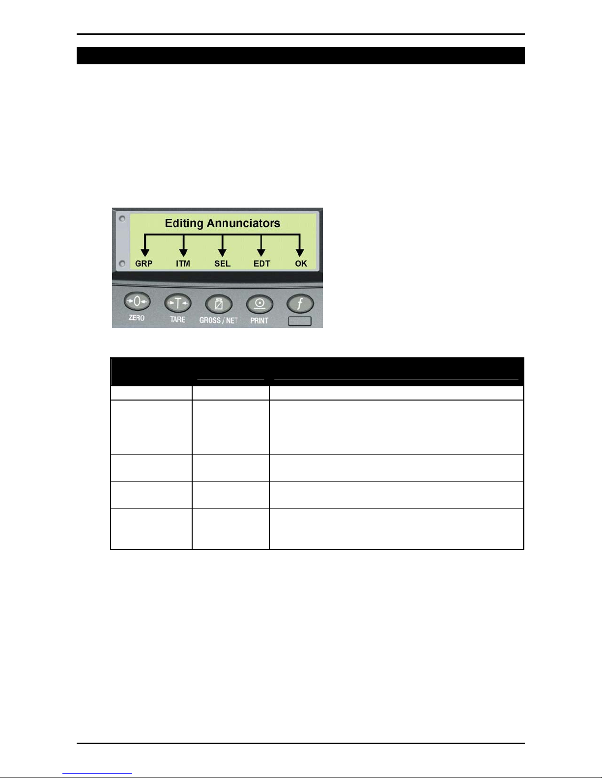
When in Setup the instrument displays editing annunciators. Figure 13 identifies
each of the editing annunciators. When in Setup, press the corresponding keypad
key below the annunciator.
Figure 13: Editing Annunciators
Editing
Annunciator
GRP
ITM
SEL
EDT
OK
Key Name Description
ZERO
TARE
GROSS/NET
PRINT
OK
(FUNCTION)
• Steps through the list of Groups.
•
Steps through the list of Items.
•
Press this key to accept changes and return to
the menus.
•
(Also refer to the OK description below.)
• Moves the editing cursor in some editing
modes.
• Steps through the available options when
editing a particular item.
•
Press this key to accept changes and return to
the menus.
• (Also refer to the ITM description above.)
Page 14 003R-618-100
Page 17

4.2. Numeric Entry
A numeric entry box allows the input of a number. When entering a number, the
display will show digits with the currently selected digit flashing. The
pressed to select a digit to change. When the digit is selected the
pressed to change the digit from 0 through 9. The left most digit can also be
changed to a dash (-) to enter a negative number. The
accept the number that has been entered and return to the menu item.
Upper and lower limits are placed on some entries and an entry outside this range
will cause the instrument to display dashes (ie. - - - - - -).
Reference Manual Rev 1.0
<OK>
<SEL>
<EDT>
key is
key is
key is pressed to
Example:
•
Press
•
Press
•
Press
•
The currently chosen digit will be flashing. Press <SEL> to advance to the next
When in Setup follow the steps below to set Build, Max Capacity.
<GRP>
<ITM>
<SEL>
repeatedly to display the
repeatedly to display the
to select
digit.
•
When the digit to edit is flashing, press
through 9.
•
When the new digit to be set is flashing either press
digit to edit and repeat the previous step; or press
of the displayed digits (including the flashing digit) and re-display the menu item
name.
4.3. Selections and Options
A selection entry requires the choice of a single option from a list. When a Group
and Item have been chosen, the
that item. The
<EDT>
key can be used to cycle through the options for that item.
When the desired option is displayed the
displayed option and re-display the item name.
Example: When in Setup follow the steps below to set Options, Filter.
• Press <GRP> repeatedly to display the OPTION group.
•
•
•
•
Press
Press
Press
Press
<ITM>
<SEL>
<EDT>
<OK>
repeatedly to display the
to select
to cycle through the options for that item.
<ITM>
or
item name.
BUILD
CAP
CAP
and display the current setting (eg. 0000.00kg).
<EDT>
<SEL>
key is used to display the current setting for
<OK>
FILTER
FILTER
and display the current setting.
group.
item.
repeatedly to cycle from 0
<SEL>
<OK> or <ITM>
to move to the next
to accept all
key can be pressed to accept the
item.
to accept the displayed option and re-display the menu
003R-618-100 Page 15
Page 18
Reference Manual Rev 1.0
5. Basic Operation
In the most basic configuration, the instrument provides a simple weight readout.
5.1. Display and Controls
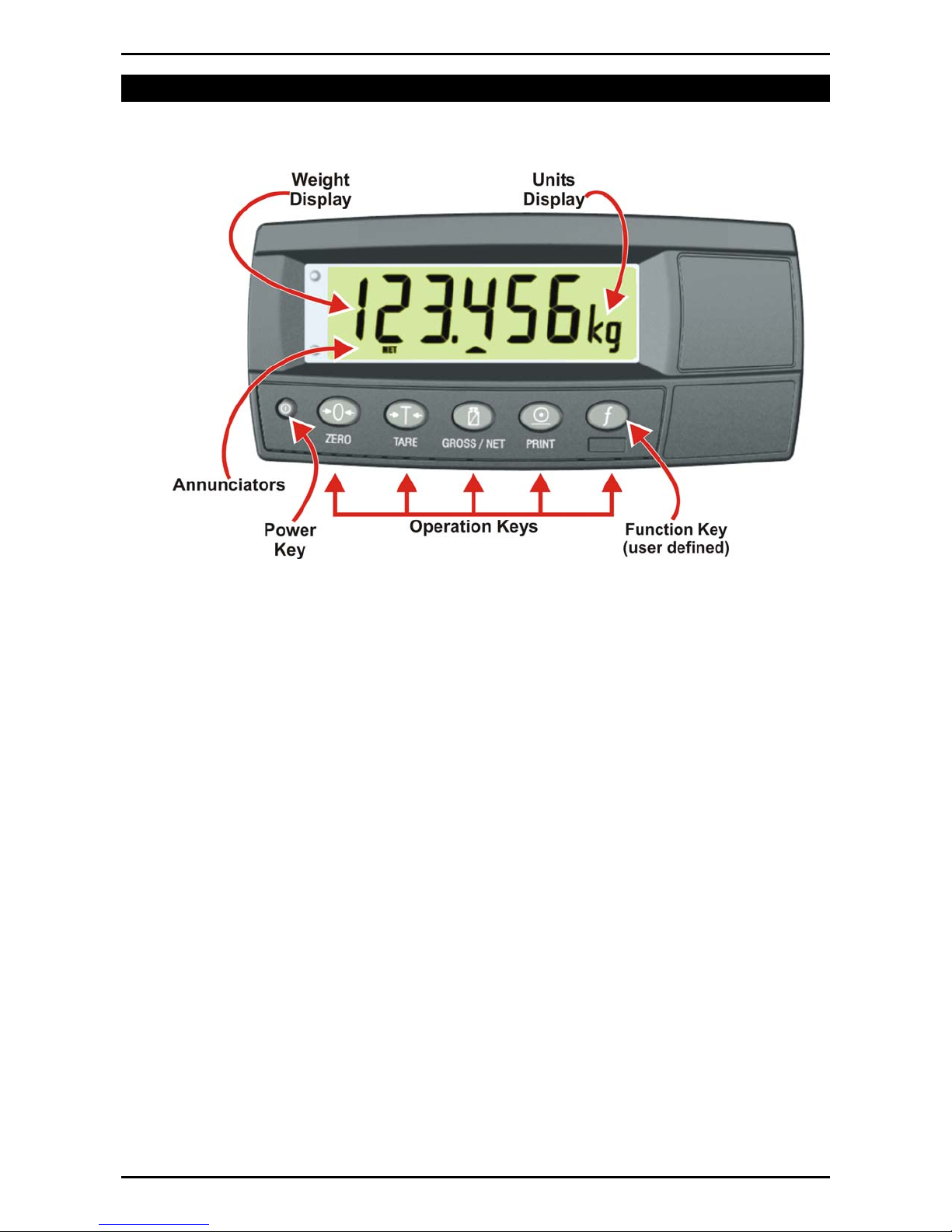
Figure 14: Display and Controls Illustration
5.1.1. Front Panel: Visual Display
The front panel has a six-digit LCD display. Figure 14 shows the main elements of
the front panel.
The instrument has various main display sections for the visual output of weight
information. Each display section is described below.
• Weight Display
The Weight Display indicates the weight readings, setup information, errors and
warnings.
• Units Display
The Units Display shows the units of the weight reading as either grams (g),
kilograms (kg), pounds (lb), tonnes (t) or none ( ). If the instrument is set up for
counting the units display will show pieces (p).
Page 16 003R-618-100
Page 19
Reference Manual Rev 1.0
• Status Annunciators
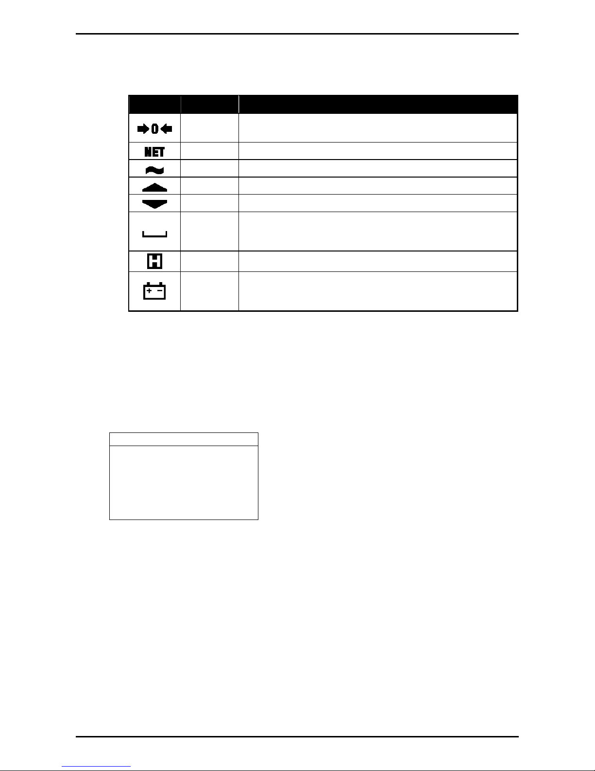
Status annunciators show the following:
Symbol Name Description
ZERO
NET
MOTION
OVER
UNDER
ZERO
BAND
HOLD
LOW
BATTERY
Table 1: Status Annunciators
When in Setup the editing annunciators are shown to identify the function of the
front panel keys (ie.
to Editing Annunciators page 14.
5.2. Operation Keys
Visible when the gross reading is within ± ¼ of a division of
true zero.
Visible when the displayed reading represents NET weight.
Visible when the displayed reading is not stable.
Visible when the setpoint weight is over the setpoint target.
Visible when the setpoint weight is under the setpoint target.
Visible when the displayed weight is within the zero 'dead'
band setting. (The zero band symbol shows near the top
right corner of the display.)
Visible when the displayed reading is held.
Visible when battery voltage is too low and batteries need
replacing or recharging. (The low battery symbol shows in
the top right corner of the display.)
GRP, ITM, SEL, EDT
and
OK
). For more information refer
The instrument has the following operation keys:
• POWER
Primary Operation Keys
•
ZERO
• TARE
•
GROSS/NET
•
PRINT
•
FUNCTION (user defined)
Each of the primary
operation keys has two
separate functions.
5.2.1. Primary Function
A single press of each key triggers the weighing operation printed on it. The
instrument allows individual keys to be disabled in the setup. All keys are enabled
at the factory, but some keys may have been intentionally disabled (locked) during
installation. If a key has been locked, a long beep sounds when it is pressed. If
however, the key beeps normally, but does not appear to trigger the desired action,
it is waiting for the weight reading to settle before the action can proceed.
5.2.2. Editing Function
Available during digital setup and calibration. This function is displayed using the
editing annunciators above each key. Refer to Editing Annunciators page 14.
003R-618-100 Page 17
Page 20

Reference Manual Rev 1.0
5.3. Stability Considerations
Once a <ZERO>, <TARE> or <PRINT> key is pressed the instrument waits for a
stable valid reading before performing the associated operation. If the weight
readings remain unstable or invalid due to some diagnostic error for longer than 10
seconds, the operation is cancelled and the STABLE ERROR message is
displayed.
To improve the stability of the weight reading, increase the filtering or relax the
motion detection criteria. Refer to FILTER (Reading Average) page 28 and
MOTION (Motion Detection) ⊗ page 28 for more information.
5.4. POWER Key
<POWER>
The
key is used to turn the instrument on and off. To initially turn
the instrument on, press and hold the <POWER> key. The display will show
the following:
•
Display segments will light and then clear.
•
Software Version (eg. V1.0).
•
Calibration Counter (eg. C.00010). Refer to Calibration Counter page 23 for
more information.
•
The current weight will then display.
To turn the instrument off, press and hold the
The instrument will display
When using batteries the backlight will automatically turn off to conserve power after
a short period of inactivity. A short press of the <POWER> key will turn the
backlight on again. Refer to B.LIGHT (Backlight Operation) page 31 for more
information.
Note: The <POWER> key can be locked to prevent the instrument being turned off
from the front keypad. Refer to KEY.LOC (Front Panel Key Locking) page 31 for
more information.
5.4.1. Automatic Operation
<POWER>
The
key on the instrument is unusual in that it has a memory function
associated with it. This means that the state of the power setting is remembered
even if external power is interrupted. It is therefore possible to turn the instrument
on in the safe knowledge that it will operate whenever external power is available
and will not need to be manually turned on again if the power is interrupted.
5.5. ZERO Key
When an empty scale has drifted away from a true zero reading, this key
is used to perform a zero adjustment on the scale display. The zero
adjustment is stored when power is removed and is re-used when next
powered up.
<POWER>
OFF
followed by the three-second countdown.
key for three seconds.
The amount of weight that may be cancelled by the <ZERO> key is limited via an
item in the Setup of the instrument. Refer to Z.RANGE (Allowable Zero Operating
Range) ⊗ page 29 for more information.
Long Press: When the indicator is set to Industrial mode a long press of the
<ZERO>
key will remove any stored zero adjustment. Refer to Industrial vs OIML
and NTEP Modes page 22 for more information on modes.
Page 18 003R-618-100
Page 21
5.6. TARE Key
This key is used to temporarily set the scale to zero (such as cancelling
the weight of a carton before performing a filling operation). The display
will show the Net weight and the NET annunciator will be lit.
The <TARE> key can operate in all modes (ie. Industrial, OIML and
NTEP). Refer to Industrial vs OIML and NTEP Modes page 22 for more
information.
The weight tared is deducted from the allowable range of the scale, reducing the
maximum weight that can be displayed.
The tare adjustment is stored when power is removed and is re-used when next
powered up.
5.7. GROSS/NET Key
This key toggles the weight display between the Gross weight and the
Net weight (provided that a Tare has previously been acquired using the
<TARE> key).
Reference Manual Rev 1.0
5.7.1. opto-LINK Activation
This feature is used to temporarily connect a PC to the instrument for calibration and
setup purposes.
A long press of the
<GROSS/NET>
key will toggle the opto-LINK infrared
communications On/Off.
When the opto-LINK has been (enabled) the following will occur:
• The instrument briefly displays the prompt rin-L.
•
The editing annunciators (ie. GRP, ITM, etc.) will flash for up to five minutes
while the instrument searches for activity. During this period, the instrument also
disables the RS-232 communications.
•
Activity Located: If the instrument is successful in locating activity, the editing
annunciators will continue to flash during the entire period of communications.
• No Activity Located:
If the instrument
fails
to locate activity, the opto-LINK will
be disabled and the editing annunciators will stop flashing. The instrument will
also revert back to the normal RS-232 communications (ie. the SERIAL:TYPE
setting will be re-activated).
003R-618-100 Page 19
Page 22
5.8. PRINT Key
If a printer or computer has been attached to the instrument and the
manual print function has been selected, the
output of the current weight reading. The
while waiting for the printer to accept data. If the printer is offline the
PRINT
prompt will remain for a maximum of 10 seconds before the operation is
cancelled. Each weight printed is automatically added to an internal Total Weight.
Reference Manual Rev 1.0
<PRINT>
PRINT
prompt is displayed
key will trigger an
Long Press:
A long press of the
then cleared automatically.
5.9. FUNCTION Key
When leaving the factory, the <FUNCTION> key is blank and has no
primary function pre-programmed. The primary function of this key can
be selected from a number of different functions including peak-hold,
counting, etc. Refer to Special Functions page 43 for details of the
available functions. Each primary function has an associated overlay sticker that
should be applied to the
Long Press:
A long press of the
functions depending on the primary function of the key.
<PRINT>
<FUNCTION>
key will print the total. The total weight is
key to label the function of the key.
<FUNCTION>
key may be used for certain
Page 20 003R-618-100
Page 23
Reference Manual Rev 1.0
6. Configuration Issues
6.1. General Setup Information
Configuration and calibration can be performed entirely from the front panel, using
the digital setup facility. When
and care must be taken to ensure no accidental changes are made to calibration
and trade settings. In addition, there is also
access
trade sensitive can be changed.
Full and Safe Setup can be passcode protected to prevent unauthorised or
accidental tampering. If the scale has been passcode protected, the setup menus
cannot be accessed until the correct code has been entered.
6.2. Basic Weighing Terminology
The following terms are used throughout the setup procedure. Knowledge of these
basic weighing terms is beneficial in setting up and calibrating the instrument.
.
This setup method ensures that only settings that are not calibration or
Full Setup
is used, all menu items are accessible
Safe Setup
that provides restricted
Note:
Descriptions of these and other terms used in this manual are listed in the
Glossary Terms page 52.
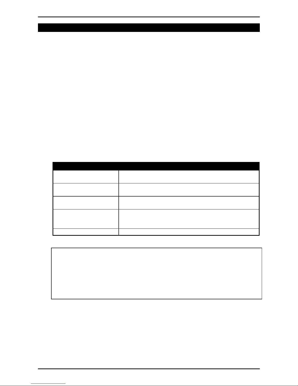
Term Definition
Units Units of measurement (kilograms, tonnes, pounds,
etc.).
Full Scale Total change in weight between zero gross load and full
capacity gross load.
Resolution or Count-by Smallest change in weight units that the display can
show.
Total Number of
Graduations
Maximum number of display steps between zero gross
load and full capacity gross load. It is equal to full scale
divided by the count-by.
Division A single graduation.
Example
This example provides a check to ensure the capability of an indicator to read a
stable weight on extremely small divisions compared to the load cell capacities.
The check is to find out what the micro-Volt per division is and then compare this to
the manufacturer's specification. If the manufacturer's specification is smaller than
the calculated value, the unit is within the requirements of operation.
Note:
The capability of an indicator may be different than the trade approval limit of
the micro-Volt per division.
A 10,000kg 2.0mV/V load cell is used in an application requiring a 5000kg full scale,
with weight displayed in 5kg increments.
The values are:
•
Units = kg
•
Full Scale = 5000
•
Count-by = 5
003R-618-100 Page 21
Page 24
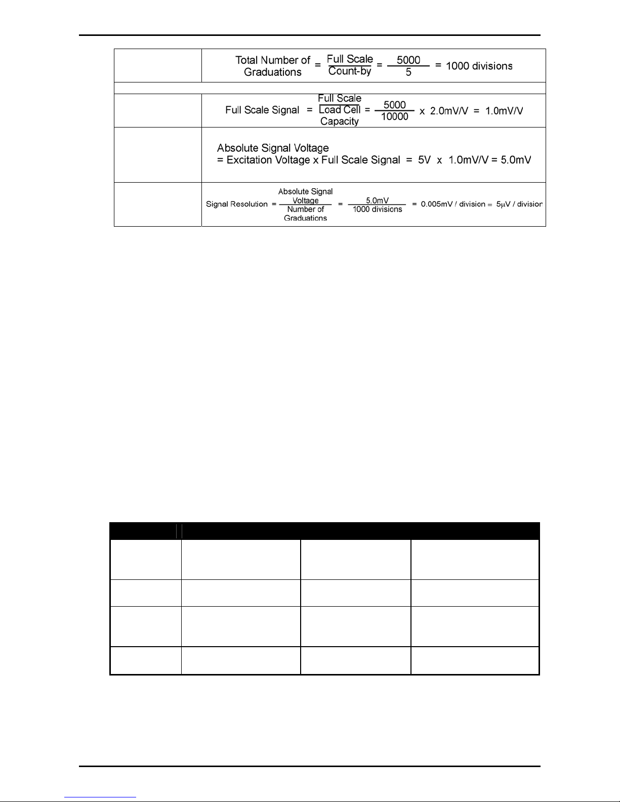
Calculating the total
number of
graduations:
Signal voltages can be calculated as follows:
Calculating the full
scale signal (load
cell):
Since the instrument
uses 5V load cell
excitation, the
absolute signal
voltage is:
Calculating the
signal resolution:
6.3. Filtering Techniques
There is a trade off between noise filtering and the step-response time of the
system. The step-response is defined as the time between placing a weight on the
scale and the correct stable weight reading being displayed. This does not affect
the number of readings per second that are taken. It simply defines the amount of
time that is required to determine a final weight reading.
Reference Manual Rev 1.0
The FILTER setting in the instrument setup shows the amount of time over which
the averaging is taken. Increasing the averaging time will result in a more stable
reading but will extend the time it takes the instrument to settle to a final reading.
Refer to FILTER (Reading Average) page 28.
6.4. Industrial vs OIML and NTEP Modes
The instrument may be operated in Industrial, OIML or NTEP mode. (
NSC requirements, use the OIML setting.) The OIML and NTEP modes restrict
certain aspects of the operation of the instrument to ensure compliance with the
respective trade certified standards. For more information refer to the Calibration
Counter section below and also to the USE (Scale Use) ⊗ section page 28 for setup
information. The following table lists the operation differences for each of these
modes.
Element Industrial OIML NTEP
Underload
Overload
Tare
–105% of full scale –1% or –2% of full
105% of full scale Full scale +9
No restrictions on
Tare
Test
Modes
Unlimited time
allowed
scale depending on
zero range setting
divisions
Tare values must
be > 0
Limited to five
seconds
Note:
For
Same as OIML
105% of full scale
Tare values must be >
0 and rounded to the
nearest graduation
Limited to five seconds
Table 2: Industrial vs OIML and NTEP Modes
Page 22 003R-618-100
Page 25
6.5. Calibration Counter
Within Setup there are a number of critical steps that can affect the calibration
and/or legal for trade performance of the instrument. If any of these steps are
altered, the trade certification of the scale could be voided.
The instrument provides built-in calibration counter(s) to monitor the number of
times the critical steps are altered. The value of a counter is stored within the
instrument and can only be reset at the factory. Each time a critical step is altered,
the counter will increase by one. Whenever the instrument is powered up, or setup
mode is entered/exited, the current value in the counter is displayed briefly (eg.
C00010).
Reference Manual Rev 1.0
Note:
When the Scale Use is set to NTEP two counters will display. Refer to USE
(Scale Use) ⊗ page 28 for setup information. The table below describes when the
counter(s) will increment for Industrial, OIML or NTEP modes.
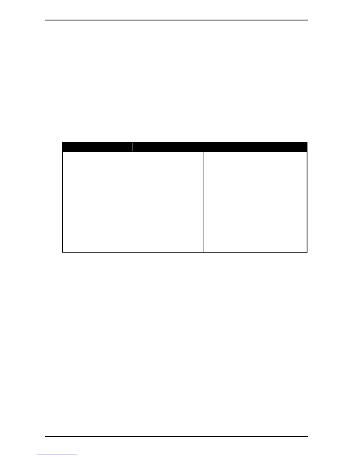
Industrial OIML NTEP
Calibration
The
Counter
increments
when trade critical
settings, marked with
⊗,
are changed. An
example of the
counter is C.00019.
Calibration
The
Counter
increments
when trade critical
settings, marked with
⊗,
are changed. An
example of the
counter is C.00019
Calibration Counter
The
increments when trade critical
settings in the Calibration (CAL)
menu, marked with
⊗,
are
changed. An example of the
counter is
C.00010
.
Configuration Counter
The
increments when other trade
critical settings (ie.
not
in the
CAL menu), marked with ⊗, are
changed. An example of the
counter is
F.00009
.
The value(s) of the counter(s) is written on the tamperproof trade label on the front
of the indicator for trade-certified applications and functions as an electronic seal. If
any legal for trade settings are changed on the instrument, the current value of the
calibration counter will be different from the recorded value and the seal is broken.
In this manual, items marked with ⊗ indicate that the setting is legal for trade critical
settings.
003R-618-100 Page 23
Page 26

6.6. Passcodes
The instrument has two levels of passcodes to provide a security lock on accessing
Setup via the keypad.
• Full Setup Passcode
•
Safe Setup Passcode
The Full Setup passcode can also be used to access Safe Setup.
6.6.1. Full Setup Passcode
Setting a passcode for Full Setup restricts any access to Full Setup. Refer to
FULL.PC (Full Security Passcode for Digital Setup) page 30.
6.6.2. Safe Setup Passcode
Setting a passcode for Safe Setup restricts access to Safe Setup functions. Refer
to SAFE.PC (Safe Security Passcode for Digital Setup) page 30.
6.6.3. Setup Lock-Out
Reference Manual Rev 1.0
If an attempt is made to enter Full or Safe Setup using an incorrect passcode, the
instrument will respond with the message
ENTRY DENIED
and then the user will be
returned to normal operating mode. A passcode counter has been set so that only
three failed attempts can be made to access Full/Safe Setup. On the fourth attempt
the user will be 'locked out' of Full/Safe setup. Should this occur the ENTER PASS
prompt will not display, but instead the
ENTRY DENIED
message displays and
returns the user to the normal operating mode. To rectify this issue the instrument
must be turned off. When the instrument is turned back on the passcode counter is
reset to zero (allowing the user to enter the correct passcode).
Page 24 003R-618-100
Page 27
Reference Manual Rev 1.0
7. Setup
The instrument digital setup facilities provide the means to configure and calibrate the
instrument.
7.1. Accessing Setup
There are two methods to access the Setup area. For further details of menu items
available in each setup mode, refer to the Setup Menu Quick Reference page 48.
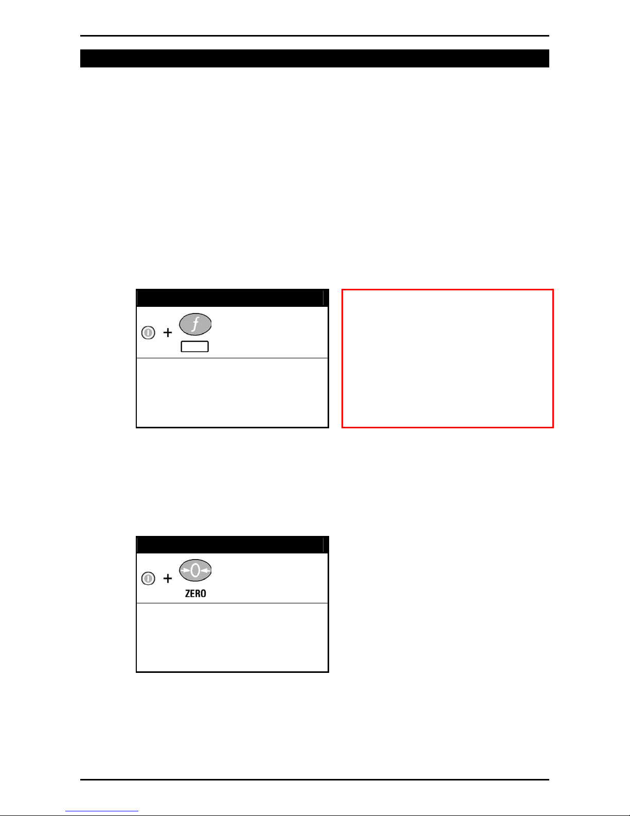
• The Full Setup method provides access to all functions in Setup, including legal
for trade and calibration sensitive settings. Changes in Full Setup mode may
result in the calibration counter being incremented. Items marked with ⊗
indicate that the setting is trade critical. Changes to passcodes and restoring
the factory default settings can only be accessed in Full Setup mode. These
items will however not increment the calibration counter. If an attempt is made
to enter Full Setup using the incorrect passcode, the instrument will respond with
the message
information.
Full Setup
To access
the instrument is on. Then press
and hold both the <POWER> and
<FUNCTION> keys together for
two seconds.
ENTRY DENIED
Full Setup
, first ensure
. Refer to Passcodes page 24 for more
WARNING
All items in all menus will be
enabled in Full Setup.
Care should be taken to avoid
inadvertently altering the Build or
Calibration settings.
•
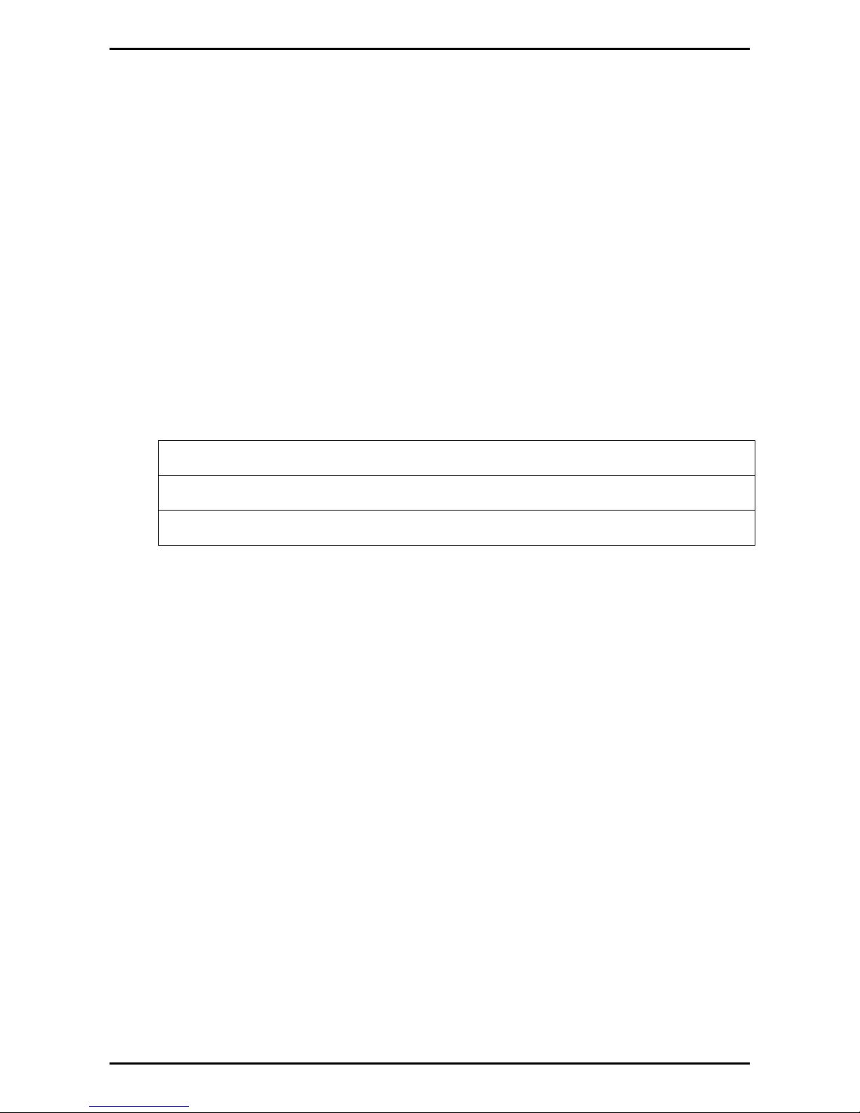
Safe Setup
The
made in this mode will not increment the calibration counter. In this manual,
items marked with ⊗ indicate that the setting is trade critical. If an attempt is
made to enter Safe Setup using the incorrect passcode, or if an attempt is made
to alter a trade critical setting while in Safe Setup, the instrument will respond
with the message
information.
Safe Setup
To access
the instrument is on. Then press
and hold both the <POWER> and
<ZERO> keys together for two
seconds.
method restricts access to the Trade Critical settings. Changes
ENTRY DENIED
Safe Setup
, first ensure
. Refer to Passcodes page 24 for more
003R-618-100 Page 25
Page 28
Reference Manual Rev 1.0
7.1.1. Setup Display Prompts
When accessing Full or Safe Setup the instrument will beep twice and then display
the following:
•
FULL or SAFE (depending on setup access type)
•
SETUP
•
Software Version (eg. V1.0)
•
Calibration Counter (eg. C.00010). Refer to Calibration Counter page 23 for
more information.
• If a passcode has been configured, the ENTER PASS prompt will display and
the setup passcode must be entered to gain access. Refer to Passcodes page
24, SAFE.PC (Safe Security Passcode for Digital Setup) page 30 and FULL.PC
(Full Security Passcode for Digital Setup) page 30 for more information.
•
The title of the first Group (ie.
7.2. Exiting Full or Safe Setup
To save settings, exit setup and return to the normal weighing mode use one of the
following methods:
BUILD
) will then be displayed.
• Method 1:
Press and hold both the
together for two seconds.
• Method 2:
Press and hold both the
two seconds.
• Method 3:
Press the
<ITM> or <ITM>.
The instrument will beep and then display the following:
•
SAVING
•
Software Version (eg. V1.0)
•
Calibration Counter (eg. C.00010). Refer to Calibration Counter page 23 for
more information.
•
The current weight will then display.
Warning:
If the power is interrupted while in setup (ie. by disconnecting the power
cable or pressing the
7.3. Groups and Items
All keypad setup options in the instrument are organised in a tree structure made up
Groups
of
and
Items
as follows (GROUP:ITEM). Refer to Setup Menu Quick Reference page 48 for a
list of all Groups and Items.
<GRP>
<POWER>
<POWER>
<POWER>
key repeatedly. When
key), unsaved settings will be lost.
<FUNCTION>
and
<ZERO>
and
- End -
keys
keys together for
displays press
. To simplify this document, Groups and Items will be notated
7.3.1. GRP (Group)
Setup is divided into a series of Groups. Each group has a distinctive group title.
All options in any one group have related functions. The <GRP> key can be used to
cycle through the available groups.
Page 26 003R-618-100
Page 29

7.3.2. ITM (Item)
Each group is divided into individual Items. Each item represents a parameter that
can be changed. Pressing the <ITM> key will enter the displayed group, allowing
access to the items within the group. The <ITM> key can be used to cycle through
the available items. The <SEL> key is then used to edit the item.
7.4. Setup Menus
The following sections describe the setup parameters of each of the Groups and
Items in Setup.
7.4.1. BUILD (Scale Build)
Settings within this Group are used to configure the indicator to suit the current
application. It is important to fully set the options within this group before calibration
is attempted. Later changes to items within this group may invalidate the current
calibration data.
• DP (Decimal Point Position) ⊗
Reference Manual Rev 1.0
Sets the location of the decimal point on the display. To avoid confusion, set
this parameter first so that all other weight related values are displayed with the
decimal point in the correct position.
•
Can be set from 000000 (none) to 0.00000
• Default: 000000
• CAP (Maximum Capacity) ⊗
Sets the nominal maximum capacity (or full scale) of the scale. This is set in
weighing units (eg. kg, t, etc.), with the decimal point in place. For example, if a
scale is to weigh 500.0 kg in 0.5 kg increments, CAP is set to 500.0, and RES is
set to 5.
• Range: 000100 to 999999
•
Default: 003000
• RES (Count-by Resolution) ⊗
Sets the resolution (or Count-by) of the display. The resolution is the number
by which the indicator will count.
•
Options are: 1, 2, 5, 10, 20, 50 or 100
• Default: 1
• UNITS (Weighed Units) ⊗
Sets the units for display and printing.
•
Options are: (g) grams, (kg) kilograms, (lb) pounds, (t) tonnes, ( ) none (ie.
other units).
•
Default: kg
• HI.RES (High Resolution x 10 mode) ⊗
Sets the instrument to display weight at 10 times resolution. This is intended for
test purposes but may be used for non-trade weighing.
•
Options are: ON or OFF
• Default: OFF
003R-618-100 Page 27
Page 30

Reference Manual Rev 1.0
• CABLE (4-Wire or 6-Wire) ⊗
Sets the load cell input to operate in 4-wire (auto sense) or 6-wire mode.
• Options are: 4 or 6
•
Default: 6
7.4.2. OPTION (Scale Options)
Items within this Group are used to configure the operating parameters of the scale.
• USE (Scale Use) ⊗
This is where the basic use of the scale is set. This setting configures the
instrument for Industrial, OIML or NTEP operation. Refer to Industrial vs OIML
and NTEP Mode page 22 for more information.
• Options are: INDUST (Industrial), OIML or NTEP
•
Default: INDUST
• FILTER (Reading Average)
The instrument can average a number of consecutive readings when calculating
the displayed weight. This is used to dampen unwanted weight fluctuations
caused by vibrations or dynamic forces. High settings will stabilise the display
at the expense of rapid response to sudden weight changes.
•
Options are: NONE, 0.2, 0.5, 1.0, 2.0, 3.0, 4.0 (time in seconds)
•
Default: 0.5 (seconds)
• MOTION (Motion Detection) ⊗
Sets how much weight variation over a defined time period is allowed before the
displayed weight is deemed to be unstable. This value is displayed as weight
change (0.5 or 1.0 graduations) per second. When set to
Detection is ignored and ZERO, TARE and PRINT actions are instantaneous.
•
Options: OFF, 0.5-1.0, 1.0-1.0 (graduations per second)
•
Default: 0.5-1.0 (0.5 graduations per second)
OFF
, the Motion
• INIT.Z (Initial-Zero on Startup)
This function can be used to automatically ZERO the indicator during power-up.
The amount of weight that can be zeroed is limited to +/– 10% of full scale.
•
Options are: ON or OFF
•
Default: OFF
• Z.TRAC (Zero Tracking Sensitivity) ⊗
Zero tracking allows the display to adjust for minor changes in the zero balance
of the scale. When enabled, the instrument will track weight readings within the
zero 'dead' band back to exactly zero at a maximum rate of 0.5 (SLOW) or 10
(FAST) graduations per second.
•
Options are: OFF, SLOW, FAST
•
Default: OFF
Page 28 003R-618-100
Page 31

• Z.RANGE (Allowable Zero Operating Range) ⊗
This setting restricts the range over which the Zero functions can operate.
• Options are: -2_ 2, -1_ 3, -20_20
•
Default: -2_ 2 (–2% to +2%)
• Z.BAND (Zero 'Dead' Band) ⊗
This is an adjustable margin either side of true zero that defines the zero 'dead'
band. The zero 'dead' band is used by the automated functions to determine
zero load (eg. a setting of 4 specifies that readings between –4.5 and 4.5 are
considered to be zero).
When the displayed weight reading is within this band the instrument displays
zero band
the
•
Settable over the full weight range. Always enter a number in multiples of
display units. Refer to RES (Count-by Resolution) ⊗ page 27 for more
information.
•
Default: 0 (ie. –0.5 to 0.5 graduations)
7.4.3. CAL (Scale Calibration)
annunciator. Refer to Status Annunciators page 17.
Reference Manual Rev 1.0
Items within this group perform various calibration routines. For detailed scale
calibration procedures refer to Calibration page 36. Certain items in the Scale Build
can affect the calibration of the scale. Always check that these sections are
correctly configured to suit the current application before attempting to calibrate the
scale.
• ZERO (Zero Calibration) ⊗
Select to perform Zero Calibration. While the zeroing is in progress the display
will show Z.in P. Refer to ZERO (Zero Calibration Routine) page 37.
• SPAN (Span Calibration) ⊗
Select to perform Span Calibration. While the span calculation is in progress the
display will show S.in P. Refer to SPAN (Span Calibration Routine) page 37.
• ED.LIN (Edit Linearisation Points) ⊗
Select to view linearisation setup and start linearisation routines. While
linearisation is in progress the display will show
L.in P
. Refer to ED.LIN (Edit
Linearisation Points) page 39 for more information.
• CLR.LIN (Clear Linearisation Points) ⊗
Select to view linearisation setup and select linearisation points to clear. Refer
to CLR.LIN (Clear Linearisation) page 39 for more information.
• DIR.ZER (Direct Zero Calibration) ⊗
Select to enter the mV/V value of the zero calibration directly. This feature is
used to enable approximate calibrations to be performed in situations where a
standard ZERO calibration is impractical (eg. calibration on a partially filled silo).
003R-618-100 Page 29
Page 32

Reference Manual Rev 1.0
• DIR.SPN (Direct Span Calibration) ⊗
Select to enter the mV/V value of the full scale capacity of the scale build. This
feature enables the instrument to be calibrated based on the rated output
capacity of the load cells rather than using test weights. The accuracy of this
method is limited to the accuracy of the published load cell ratings.
• FAC.CAL (Restore Default Factory Calibration) ⊗
Select this choice to restore default factory calibration. This restores all
calibration critical settings in the BUILD, OPTION and CAL menus back to
factory defaults. The instrument will prompt with Cont. N. Press <EDT> to
change to Cont. Y and <OK> to continue. If Cont. Y is chosen and then <OK>
or <ITM> is pressed, the instrument will display DONE to indicate that the
operation has been completed.
7.4.4. SPEC (Special Settings Menu)
Settings within this group control features including passcodes, key locking, key
functions and display settings.
• SAFE.PC (Safe Security Passcode for Digital Setup)
SAFE.PC
The
(Safe Passcode) allows partial access to Digital Setup (ie. only
non calibration/trade critical settings can be changed). For the Safe Passcode
to have any effect, the FULL.PC passcode must also be set. The default
passcode setting is
000000
that allows free access. Any other number will
enable the passcode functions and restrict access. Refer to Passcodes page
24 and Accessing Setup page 25 for more information.
•
Range 000000 to 999999
• Default: 000000
• FULL.PC (Full Security Passcode for Digital Setup)
The FULL.PC (Full Passcode) can be set to restrict access to Full Digital Setup.
This passcode is used to prevent unauthorised or accidental tampering in the
instrument setup. The default passcode setting is
access. Any other number will enable the passcode functions and restrict
access. Refer to Passcodes page 24 and Accessing Setup page 25 for more
information.
• Range 000000 to 999999
•
Default: 000000
It is important to note that when restricting Full access to Setup the passcode
must not be forgotten. It is only possible to circumvent the passcode at the
factory. Care must be taken when setting the Full Digital Setup Passcode to
ensure that the instrument does not become permanently locked.
000000
that allows free
Page 30 003R-618-100
Page 33

Reference Manual Rev 1.0
• KEY.LOC (Front Panel Key Locking)
This item allows individual keys to be locked and unlocked. The display shows
a dash (–) to indicate that a key is locked (inactive) or characters for each key
that is active (ie. the characters
<POWER>
key and the numbers
keys. The operation keys are numbered from the left with the
P12345
1234
display). The letter P represents the
and 5 represent the remaining operation
<ZERO>
key
being number 1.
Note: When the <POWER> key is locked, the instrument cannot be turned off
from the front keypad.
•
Default: P12345 - All keys are unlocked (active)
• KEY.FN (Key Functions)
The function of the keypad
<FUNCTION>
key can be selected here. Refer to
Special Functions page 43 for details of the available key functions.
Options are:
•
NONE
•
TEST
•
Default: NONE
•
AUT.OFF (Auto Power Off / Battery Operation)
•
COUNT
•
UNITS
•
HOLD
•
PEAK.H
•
LIVE.WT
•
SHOW.T
The instrument can be set up to automatically power down after a period of no
activity. Weight motion, network communications or any press of the keyboard
is enough to keep the instrument powered on. When operating on batteries the
instrument will turn off after 30 minutes of inactivity even if set to NEVER.
Options are:
•
NEVER: Never power off automatically (Battery: powers down after 30
minutes)
•
1, 5,10 (time in minutes)
• Default: NEVER
• B.LIGHT (Backlight Operation)
Sets the operation of the backlight. When operating the backlight with batteries
the brightness is lowered automatically to conserve power and the backlight will
automatically turn off after 10 seconds of inactivity. To turn on again, press the
<POWER> key.
Options are:
• OFF: Backlight is off
•
ON: Backlight is always on
• Default: ON
003R-618-100 Page 31
Page 34
Reference Manual Rev 1.0
• REM.FN (Remote Function)
This item allows the indicator to be triggered from a remote input. The remote
input can be set to have no function (ie. NONE) or it can be set to mimic one of
the front five panel key functions (ie. where KEY1=ZERO, KEY2=TARE,
KEY3=GROSS/NET, KEY4=PRINT and KEY5=FUNCTION).
The remote input can also be set to BLANK where, when the remote input is
pressed and held, the indicator displays dashes (ie.
key functions are disabled. When the remote input is released the indicator
display and front key functions return to normal.
For the REM.FN to have any effect, the SERIAL:TYPE item must be set to KEY.
Refer to TYPE (Serial Output Type) below for more information.
Options are:
• NONE: No function.
•
KEY1 to KEY 5: Mimic one of the front five function keys
• BLANK: Display dashes (ie. - - - - - -) and disable front key functions.
•
Default: NONE
7.4.5. SERIAL (Serial Communications Options)
- - - - - -
) and the front five
Settings within this Group determine the serial and printing outputs. Refer to Serial
Outputs page 40 for more information on Serial configuration.
• TYPE (Serial Output Type)
Sets the function of the first serial output. The port can be disabled or set to run
as an automatic output or a network device.
Options are:
•
NET: Network Communications.
•
AUTO.1: Enables 10 Hz automatic transmission using format 1.
•
AUTO.2: Enables 10 Hz automatic transmission using format 2.
•
PRINT: Enables printer driving.
•
MASTER: Send contents of LCD display to a remote display.
• KEY: Enables the Remote Function setting (SPEC:REM.FN).
•
Default: NET
• BAUD (Serial Baud Rate)
The baud rate determines the serial data transmission speed.
• Options are: 2400, 4800, 9600
•
Default: 9600
Page 32 003R-618-100
Page 35

Reference Manual Rev 1.0
• BITS (Serial Format Options)
The Bits options allow the data transmission bit pattern and interface to be
changed. The display will show the current setting in the form
n81-
where each
character has a meaning as shown below.
Options are:
• N or O or E: Parity bit: (N) None, (O) Odd, (E) Even
•
8, 7: Number of data bits
• 1, 2: Number of stop bits
•
-, D: DTR handshake disabled or enabled
• Default: n81-. (For most applications the default setting is applicable.)
• ADDRES (Instrument Address)
Use this option to set the instrument address when operating with network
communications.
• Range 01 to 31
•
Default: 31
• RST.CON (Reset Printed Consecutive Number) ⊗
Use this option to reset the printed consecutive number back to 1. The
instrument will prompt with
<OK>
DONE
to continue. When
to indicate that the operation has been completed.
Cont. N
Cont. Y
. Press
has been chosen the instrument will display
<EDT>
to change to
Cont. Y
7.4.6. SET.PTS (Setpoint Settings)
Settings within this group configure the setpoint system. Refer to Setpoints page 42
for a detailed explanation of setpoints.
• SRC (Weight Source)
The weight source determines the weight reading that is used for the setpoint
comparisons.
Options are:
•
GROSS: Use gross weight readings always.
•
DISP: Use the displayed weight (gross or net).
•
OFF: Both setpoints are off.
•
Default: OFF
• TARG.HI (Target for Overweight)
This is the target for setpoint 1 (output 1). Weights above this target will cause
the setpoint to become active and output 1 to be driven. The instrument
displays the
• Range: –99999 to 999999
•
Default: 000000
over
annunciator. Refer to Status Annunciators page 17.
and
003R-618-100 Page 33
Page 36

• TARG.LO (Target for Underweight)
This is the target for setpoint 2 (output 2). Weights below this target will cause
the setpoint to become active and output 2 to be driven. The instrument
displays the under annunciator. Refer to Status Annunciators page 17.
•
Range: –99999 to 999999
• Default: 000000
7.4.7. CLOCK (Clock Settings)
Items within this group set date and time related functions.
• FORMAT (Date Format)
This sets the date format.
Options are:
• dd.mm.yy
•
mm.dd.yy
• Default: dd.mm.yy
• YEAR (Set Year)
•
Range: 2000 to 2099
Reference Manual Rev 1.0
•
MONTH (Set Month)
•
Range: 01 to 12
• DAY (Set Day)
•
Range: 01 to 31
• HOUR (Set Hour)
• Range: 00 to 23 (24-hour format)
• MINUTE (Set Minute)
•
Range: 00 to 59
7.4.8. TEST (Special Test Functions)
Items within this Group allow access to the testing routines for the instrument. With
these routines the scale base output can be monitored and the inputs and outputs
can be tested.
• SCALE (Scale Base Test Display)
Verifies the correct load cell capacity and/or load cell wiring is used. It sets up
the instrument as a simple test meter to measure the load cell signal output.
The display reads in milliVolts-per-Volt, factory calibrated to 0.1% worst case.
When accessing this item, initially there should be no weight on the scale. In
OIML or NTEP modes, this display is only active for five seconds before
returning to the menu.
Page 34 003R-618-100
Page 37

Reference Manual Rev 1.0
• FRC.OUT (Force Outputs)
Forces each of the output drivers in turn. All outputs turn OFF when leaving this
step. The
Pressing
<EDT>
<OK>
key will advance through each output (ie. ON.1 and ON.2).
will turn all outputs off and exit the test.
7.4.9. FACTRY (Factory Adjustment Menu)
• DEFLT (Restore Factory Settings Except for Calibration and Build)
Restores all settings in the digital setup, which are not calibration critical back to
the original
to completely reset an instrument that is being installed on a different scale.
The instrument will prompt with
<OK>
and
display
Restoring the factory options does not affect the calibration. To reset the
calibration to factory condition CAL:FAC.CAL must be used. Refer to FAC.CAL
(Restore Default Factory Calibration) ⊗ page 30. This menu item is only
available when in Full Digital Setup mode.
new
settings installed at the factory. The main use of this routine is
to continue. When
DONE
to indicate that the operation has been completed.
Cont. N
Cont. Y
. Press
<EDT>
to change to
Cont. Y
has been chosen the instrument will
7.4.10. – End – (Leaving Setup)
Refer to Exiting Full or Safe Setup page 26.
003R-618-100 Page 35
Page 38
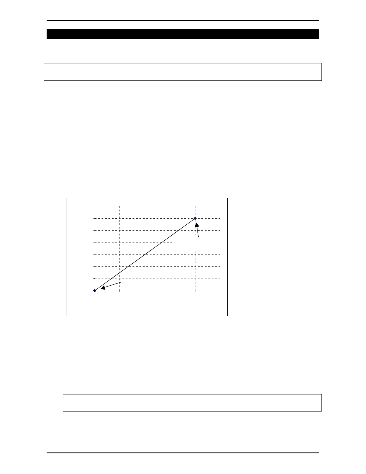
Reference Manual Rev 1.0
8. Calibration
The calibration of the indicator is fully digital. The calibration results are stored in
permanent memory for use each time the instrument is powered up.
Note: Some of the digital setup steps can affect calibration. The BUILD and
OPTION settings MUST be configured before calibration is attempted.
To perform a calibration, when in Full Setup select the
CAL
Group using the
<GRP>
key.
The calibration programme will automatically prevent the instrument from being calibrated
into an application outside of its specification. If an attempt is made to calibrate outside of
the permitted range, an error message will display and the calibration will be abandoned.
Refer to Error Messages page 49.
The instrument has a wide-range ADC. The non-trade calibration range of the instrument
extends well beyond the Trade approved range.
Note: It should not be assumed that just because the instrument has successfully
calibrated a scale, that the scale is correct for trade use. Always check the scale
build against the approval specification.
8.1. Performing a Digital Calibration with Test Weights
3500
3000
2500
2000
1500
Weight (Kg)
1000
Span Point
(preferably at full load)
500
0
0246810
Zero Point
Load Cell Output (m V)
Figure 15: Chart - Zero and Span Points to Interpolate Weight from Load Cell
The Zero setting (CAL:ZERO) specifies a gross zero point for the scale. The Span
setting (CAL:SPAN) specifies a second point
(preferably close to full scale)
used
to convert the A/D readings into weighing units (eg. kg). Select either of the Zero
(CAL:ZERO) or Span (CAL:SPAN) calibration items. It is important that an initial
Zero calibration is performed before any SPAN calibrations. The chart shown here
demonstrates how the zero and span points are used to interpolate a weight reading
from the load cell reading.
Note: Calibration points (Zero, Span and Linearisation) must be spaced by at
least 2% of Full scale from each other.
Page 36 003R-618-100
Page 39
Reference Manual Rev 1.0
8.1.1. ZERO (Zero Calibration Routine)
•
Press the
<SEL>
key to start. The display will show the current weight. Remove
all weight from the scale structure.
•
Press
<SEL>, <EDT>
or
<OK>
to execute a Zero Calibration. The display will
show Z.in.P to indicate that zeroing is in progress. When the process is
complete the display will return to weight to allow the zero to be checked.
•
Press the <ITM> key to leave the Zeroing routine or press <SEL>, <EDT> or
<OK>
to repeat the operation.
8.1.2. SPAN (Span Calibration Routine)
•
Press
•
Add the calibration test mass to the scale. The minimum acceptable span
<SEL>
or
<OK>
to start. The display will show the current weight.
calibration weight is 2% of the scale range. A weight this small may limit
calibration accuracy. The closer the test weight is to full scale the better the
accuracy.
•
Press
correct calibration weight using the
•
Press
<SEL>
<ITM>
or
or
<OK>
<OK>
to show the calibration weight value. Change this to the
<SEL>
to trigger the Span Calibration routine. The display will
show S.in P to indicate that spanning is in progress. When the process is
complete the display will return to weight to allow the new weight reading to be
checked.
•
When the Span Calibration is complete, press the
Spanning routine or press
<SEL>, <EDT>
weight and repeat the operation.
and
or
<EDT>
<OK>
keys.
<ITM>
key to leave the
to re-edit the calibration
8.2. Performing a Calibration with Direct mV/V Entry
In applications where test weights are not easily available, it is possible to calibrate
the instrument directly by entering the mV/V signal strength at Zero and full scale
Span. The Direct Zero setting (CAL:DIR.ZER) specifies a gross zero point for the
scale. The Direct Span setting (CAL:DIR.SPN) specifies the mV/V signal strength
corresponding to an applied mass equal to the full scale reading. This calibration
technique is not compatible with linearisation. Clearly the accuracy of this type of
calibration is limited to the accuracy of the direct mV/V data.
8.2.1. DIR.ZER (Direct Zero Calibration Entry)
•
Press the
<OK>
key to start. The display will show the current weight.
• Press the <OK> key to enter the Direct Zero setting. Change the mV/V setting
to the correct value for
•
Press the
<OK>
Zero
using the
key to store the new zero calibration. When the process is
<SEL>
and
complete the display will return to weight to allow the new weight reading to be
checked.
•
Press the
<ITM>
key to leave the Direct Zero routine or
operation.
<EDT>
<OK>
keys.
to repeat the
003R-618-100 Page 37
Page 40
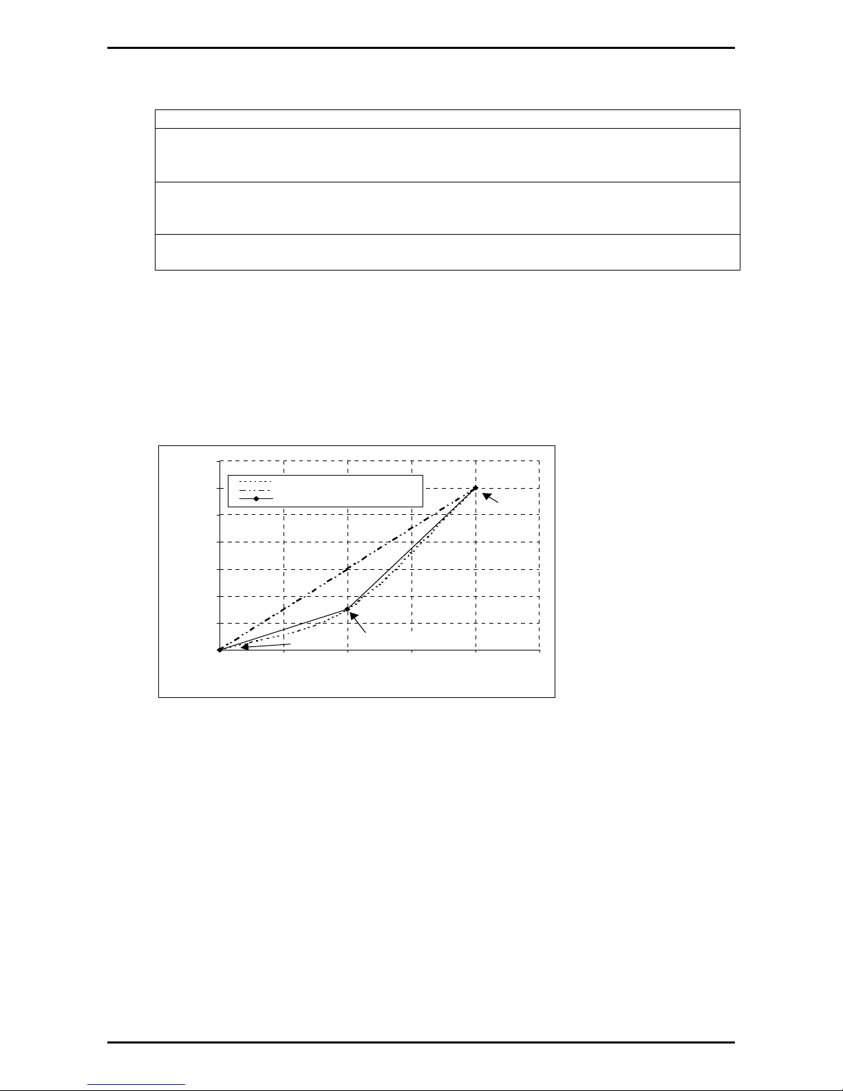
Reference Manual Rev 1.0
8.2.2. DIR.SPN (Direct Span Calibration Entry)
•
Press the
<OK>
key to start. The display will show the current weight.
• Press the <OK> key to enter the Direct Span setting. Change the mV/V setting
to the correct value for the full scale signal strength, using the <SEL> and
<EDT>
•
Press the
keys.
<OK>
key to store the new span calibration. When the process is
complete the display will return to weight to allow the new weight reading to be
checked.
• Press the <ITM> key to leave the Direct Span routine or <OK> to repeat the
operation.
8.3. Using Linearisation
This section provides instructions on the use of the linearisation. Linearisation is
used to approximate the weight output to a non-linear scale. The chart below shows
a non-linear characteristic for the load cell output. From the chart, it can be seen
that the trace with no linearisation applied is a poor approximation to the real
characteristic. By applying one or more linearisation points, more accurate weight
readings can be achieved.
3500
3000
2500
Actual Load Cell Characteristic
No Linearis ation
Linearisation Applied
Span P oint
2000
1500
Weight (Kg)
1000
500
0
0246810
Zero Po int
Load Cell Output (mV)
Linearisation Point
Figure 16: Chart - Non-Linear Characteristic for Load Cell Output
To perform a linearisation, a calibration of the zero and full scale span points must
have been performed. Both the zero and full scale calibration points are used in the
linearisation of the scale base. These two points are assumed to be accurately set
and thus have no linearisation error.
A maximum of five linearisation points can be set independently between zero and
full scale. Unused or unwanted points may also be cleared. The maximum
correction that can be applied using a linearisation point is + / - 2%.
Page 38 003R-618-100
Page 41

Reference Manual Rev 1.0
8.3.1. ED.LIN (Edit Linearisation Points)
•
Press the
Ln.ppp
<SEL>
key to step through the list of points. Each point is shown as
where n is the point number (1 to 5), and
ppp
is the approximate
percentage of full scale where the linearisation is applied. For example,
indicates that linearisation point one is active and was entered at about 50% of
full scale. Unused linearisation points are shown with a row of dashes (eg. L2. -
- -).
• Press <OK> to change the linearisation point selected or press <ITM> to exit
without making any changes.
•
After pressing
<OK>
, the current weight reading is displayed. Add the
calibration test mass to the scale. The closer the test mass is to the point of
maximum error in linearity the more effective will be the correction. Press <OK>
to enter a corrected weight value for this point or <ITM> to exit without making
changes.
•
Use the
<SEL>
and
<EDT>
keys to enter the correct value of the calibration
weight being used.
•
Press the
L.in P
<OK>
key to trigger the Linearisation routine. The display will show
to show that linearisation is in progress. When the process is complete
the display will show the weight to allow the new weight reading to be checked
before returning to the menus. Press
<ITM>
to leave the routine or
<OK>
repeat the operation.
8.3.2. CLR.LIN (Clear Linearisation)
L1.050
to
•
Press the
Ln.ppp
percentage of full scale where the linearisation is applied. For example,
<SEL>
key to step through the list of points. Each point is shown as
where n is the point number (1 to 5), and
ppp
is the approximate
L1.050
designates that linearisation point one is active and was entered at about 50%
of full scale. Unused linearisation points are shown with a row of dashes (eg.
L2. - - -).
•
Press
<OK>
to choose the linearisation point to clear. The indicator will prompt
to continue with CONT. N. Press <ITM> to switch between Cont. N (No) and
Cont. Y (Yes). The <OK> key is used to accept your choice. When Cont. Y
has been chosen the cleared linearisation point then displays (eg. L1. - - -).
•
Press
<ITM>
to return to
CLR.LIN
.
Note: All linearisation points are cleared by restoring the default calibration of the
instrument. The zero and span settings are also cleared by this process.
003R-618-100 Page 39
Page 42
Reference Manual Rev 1.0
9. Serial Outputs
The instrument can support the optional temporary opto-LINK connection. In addition,
there is a single bi-directional RS-232 output. This provides a number of serial output
options allowing communications with external devices such as printers, computers, PLCs
or remote displays. Refer to opto-LINK Activation page 12. For wiring connections and
pinouts, refer to Auxiliary Connection page 9.
The serial available functions include:
•
Automatic Weight Output (two formats available)
• Network Communications
•
Master / Slave
• Printing
All serial output options are enabled and configured using the serial communications
options in the digital setup procedure. Refer to SERIAL (Serial Communications Options)
page 32.
The instrument computer communications can range from simple automatic streamed
output, through to a command-response system. In addition to the opto-LINK, the
instrument can be programmed and calibrated via the RS-232 serial port. The calibration
counter is incremented when the calibration related steps are accessed via RS-232, the
serial port or the opto-LINK. This means that calibration via the serial port or opto-LINK
cannot be carried out without affecting the certification of a trade installation.
9.1. Automatic Weight Output
The automatic output is normally used to drive remote displays, a dedicated
computer, or PLC communications.
Auto Weight Format String
The weight format string may be set to the following formats:
Format Description
AUTO1 <STX> <SIGN> <WEIGHT(7)> <STATUS> <ETX>
AUTO2 <STX> <SIGN> <WEIGHT(7)> <S1> <S2> <S3> <S4> <UNITS(3)> <ETX>
Where
• STX: Start of transmission character (ASCII 02).
• ETX: End of transmission character (ASCII 03).
• SIGN:
• WEIGHT(7):
The sign of the weight reading (space for positive, dash (-) for negative).
A seven character string containing the current weight including the
decimal point. If there is no decimal point, then the first character is a space.
Leading zero blanking applies.
• STATUS: Provides information on the weight reading. The characters
G/N/U/O/M/E represent Gross / Net / Underload / Overload / Motion / Error,
respectively.
• UNITS(3):
A three character string, the first character being a space, followed by
the actual units (eg. ^kg or ^^t). If the weight reading is not stable, the unit string
is sent as ^^^.
• S1:
Displays G/N/U/O/E representing Gross / Net / Underload / Overload / Error,
respectively.
• S2:
• S3:
Displays M/^ representing Motion / Stable, respectively.
Displays Z/^ representing centre of Zero / Non-Zero, respectively.
• S4: Displays - representing single range.
Page 40 003R-618-100
Page 43
Reference Manual Rev 1.0
• Printing
The instrument has a single fixed printing format that is as follows:
000048 06/05/2003 15:10
121.4 kg G
The first line contains a six digit sequential number that is automatically incremented
with each printing, up to a maximum of 999999. The first line also contains the
current date and time, printed in the selected format.
The second line shows the displayed reading, units and G for Gross or N for Net.
If counting is active, the printout has a third line for the counting information (p for
pieces) as follows:
164 p
Whenever a new sample is taken when counting, the instrument prints the sample
as in the following format:
SAMPLE: 100 p = 50.0 kg
In addition to the printout, the instrument adds the weight and pieces printed to the
internal weight and count totals. A long press of the <PRINT> key will print and
clear these totals. The six digit sequential number is not cleared. Following is a
sample of a total ticket:
000049 06/05/2003 15:20
90.6 kg G
000050 06/05/2003 15:21
154.9 kg G
000051 06/05/2003 15:21
50.4 kg G
000052 06/05/2003 15:21
71.0 kg G
000053 06/05/2003 15:21
13.3 kg G
ITEMS: 5
TOTAL: 380.2 kg
If counting is active each of the individual printouts would have a third line as
discussed above and the
000054 06/05/2003 15:22
13.3 kg G
27 p
000055 06/05/2003 15:23
79.3 kg G
159 p
000056 06/05/2003 15:23
117.0 kg G
234 p
ITEMS: 3
TOTAL: 209.6 kg
QTY: 420 p
TOTAL
would have an additional QTY line as follows:
9.2. Master Serial Output
In Master mode, the instrument sends out the entire contents of the LCD every
100msec. This is essentially the same as AUTO output but the format of the output
string is designed to allow a remote display to exactly copy the contents of the LCD
including all of the annunciators and user prompts, etc.
003R-618-100 Page 41
Page 44

Reference Manual Rev 1.0
10. Setpoints
The instrument is capable of working with two internal setpoints. The status of these
setpoints is displayed on the LCD. Each setpoint is associated with a physical output
driver but it may also be simply used as an indicator.
Refer to SET.PTS (Setpoint Settings) page 33 for details on settings.
10.1. Setpoint Connection
Refer to Auxiliary Connection page 9 for the method of connection of the external
output drivers.
10.2. Setpoint Operation
Setpoint 1 is configured as an overload setpoint. The SET.PTS:TARG.HI value sets
the value for the overload limit. Setpoint 2 is an underload setpoint and its limit
value is set by SET.PTS:TARG.LO value.
The SET.PTS:SRC setting allows the gross weight or displayed weight to be chosen
as the source for the setpoint operation. This allows the overload and underload
limits to be linked to gross weights always or alternatively to be linked to the current
displayed weights.
When the selected weight is greater than the TARG.HI value the over
annunciator is visible and output 1 is activated.
When the selected weight is less than the TARG.LO value the under
annunciator is visible and output 2 is activated.
Page 42 003R-618-100
Page 45
11.1. Introduction
The instrument has a special function key on the front panel. This
function of this key can be configured to any of the key functions detailed
below. Refer to KEY.FN (Key Functions) page 31 to configure the
function key.
Reference Manual Rev 1.0
11. Special Functions
When leaving the factory, the
function pre-programmed. Each primary function has an associated overlay sticker
(supplied) that should be applied to the function key to label the function. Ensure
the keypad is clean and dry before affixing the sticker. Refer to Cleaning page 6 for
more information.
11.2. Key Functions
11.2.1. NONE
When set to NONE the special function key is not used during normal operation.
This is the default setting.
11.2.2. TEST
•
Press the
<TEST>
then clear the display again before returning to normal operation.
11.2.3. COUNT
Use this key to perform pieces counting. Press the <COUNT> key to switch
between weight display and counts display. The instrument annunciator shows p for
pieces.
<FUNCTION>
key is blank and has no primary
key to clear the display then show all segments of the display
To record a new sample do the following:
• Tare off any containers.
• Place the sample on the scale
• Press and hold the <COUNT> key for two seconds. The default number of
items in the sample will be displayed.
•
Use the
•
Press
•
If printing is enabled the sample quantity and weight will be printed.
<SEL>
<OK>
<EDT>
and
keys to alter the number of items.
and the current sample will be stored against the entered items.
11.2.4. UNITS
Use the
<UNITS>
key to switch the displayed reading between
lb
and kg. This will
affect the displayed and printed weight but will not affect any data entry. The
following is a sample of a printout displaying kg and lb.
000009 06/05/2003 16:31
2.8 kg G
000010 06/05/2003 16:31
6.1 lb G
003R-618-100 Page 43
Page 46
11.2.5. HOLD and PEAK HOLD
The <HOLD> key implements a manual Hold function. The <PEAK> key
implements a Peak Hold function where the largest absolute weight, either positive
or negative is stored in the peak value (eg. -30 is larger than 25). The Hold
annunciator is active when the display is showing the held weight. Refer to Status
Annunciators page 17.
Reference Manual Rev 1.0
To perform the
Hold
function, do the following:
• Press the manual <HOLD> key once to hold the current displayed weight.
• Press the manual <HOLD> key again to return the display to normal weighing.
To perform the
•
Press the
•
Press the
•
A long press of the
Peak Hold
<PEAK>
<PEAK>
function do the following:
hold key once to show the absolute peak weight reading.
hold key again to return the display to normal weighing.
<PEAK>
hold key clears the peak value back to 0 (zero).
All printouts that print the displayed weight will use the held weight reading if it is
currently being displayed.
11.2.6. LIVE.WT
<LIVE.WT>
The
key is used to enable live weight averaging. With this feature, it is
possible to determine the weight of a continually moving mass (eg. livestock).
• Press and hold the <LIVE WT> key to switch between normal weighing and live
weight mode. The display will briefly show
NORMAL
LIVE.WT
or
.
During normal weighing, this key operates exactly like a manual <HOLD> key.
In Live-Weight mode the following sequence is followed:
•
While the net weight is within the zero 'dead' band, the instrument shows the
current weight.
•
Press the <TARE> or <ZERO> key to clear any residual weight and return the
scale to the zero state.
•
Place the mass to be weighed on the scale.
•
Once the weight moves outside the zero 'dead' band the instrument begins to
calculate a long term average that compensates for any movement in the mass.
The instrument flashes the
Hold
annunciator and shows the current average
value.
• The Hold annunciator is steady when the final sample weight is shown on the
display.
•
Press the
•
Once the weight is returned to the zero 'dead' band, the cycle can be repeated.
<LIVE WT>
key to force the sample to be re-calculated.
Page 44 003R-618-100
Page 47
11.2.7. SHOW.T
The SHOW.T item stands for Show Total. The function key will be labelled
<TOTAL>.
The PRINT key is used not only to print the current weight but also to add that
weight to the current total.
Reference Manual Rev 1.0
•
When the
<TOTAL>
key is pressed the indicator displays
count
followed by the
number of items in the total.
• After this, TOTAL is displayed followed by the current total weight.
If the total weight is too large to display in six digits, the weight is shown in two
sections labelled with the upper six digits displayed before the lower six digits.
A long press of the
<PRINT>
key causes the total accumulated weight to be printed
and then cleared. The SERIAL:TYPE option must be set to PRINT to activate this
function.
003R-618-100 Page 45
Page 48
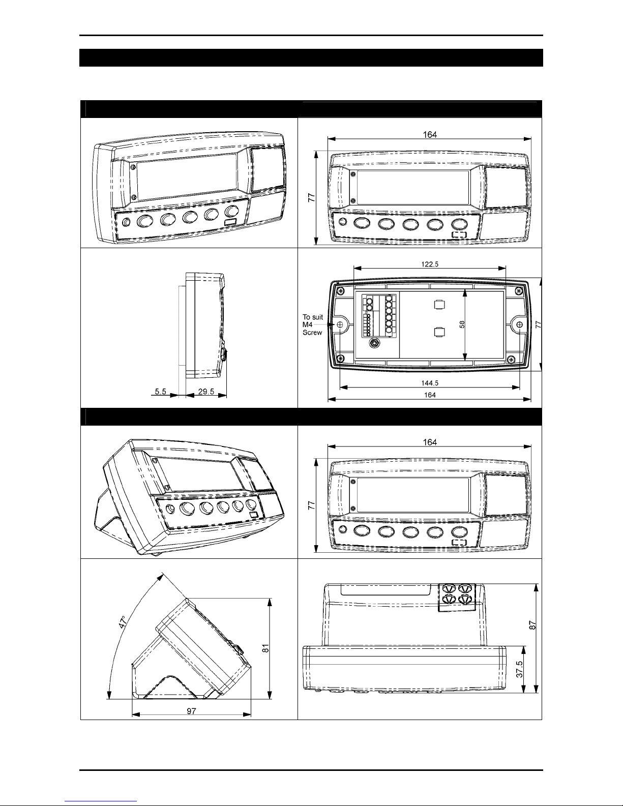
12.1. Dimensions
Reference Manual Rev 1.0
12. Appendix
Weight Indicator
3D View
Side View
Dimensions in mm (1 inch = 25.4 mm)
Front View
Back View
Weight Indicator
3D View
Side View
(Desk Mount with Battery Compartment) Dimensions in mm (1 inch = 25.4 mm)
Front View
Top View
Page 46 003R-618-100
Page 49
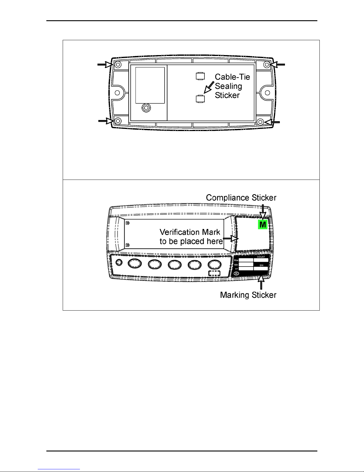
12.2. Sealing Details
where the cable-tie strain relief is attached, as indicated.
Reference Manual Rev 1.0
Affix sealing stickers to the rear of the instrument,
over one or more screws in the locations indicated.
Also affix a sealing sticker over the load cell cable
003R-618-100 Page 47
Affix stickers in the locations indicated.
Page 50

Reference Manual Rev 1.0
12.3. Setup Menu Quick Reference
Note:
⊗ Available only in Full Setup. Changing this setting
1 Available only in Full Setup. Changing this setting
will increment
will not increment
the Calibration Counter.
the Calibration Counter.
Group (GRP) Item (ITM) Page
BUILD
OPTION
⊗
DP (Decimal Point Position)
CAP (Maximum Capacity) ⊗
RES (Count-by Resolution) ⊗
⊗
UNITS (Weighed Units)
HI.RES (High Resolution x 10 mode)
CABLE (4-Wire or 6-Wire)
⊗
⊗
USE (Scale Use) ⊗
FILTER (Reading Average) 28
MOTION (Motion Detection) ⊗
27
27
27
27
27
28
28
28
INIT.Z (Initial-Zero on Startup) 28
28
29
29
29
29
29
29
29
30
30
30
CAL
SPEC
Z.TRAC (Zero Tracking Sensitivity) ⊗
Z.RANGE (Allowable Zero Operating Range) ⊗
Z.BAND (Zero 'Dead' Band) ⊗
ZERO (Zero Calibration) ⊗
SPAN (Span Calibration) ⊗
ED.LIN (Edit Linearisation Points) ⊗
CLR.LIN (Clear Linearisation Points) ⊗
DIR.ZER (Direct Zero Calibration) ⊗
DIR.SPN (Direct Span Calibration) ⊗
FAC.CAL (Restore Default Factory Calibration) ⊗
SAFE.PC (Safe Security Passcode
for Digital Setup)
FULL.PC (Full Security Passcode for Digital Setup) 30 1
KEY.LOC (Front Panel Key Locking) 31
KEY.FN (Key Functions) 31
AUT.OFF (Auto Power Off / Battery Operation)
31
B.LIGHT (Backlight Operation) 31
REM.FN (Remote Function) 32
SERIAL
TYPE (Serial Output Type) 32
BAUD (Serial Baud Rate) 32
BITS (Serial Format Options) 33
ADDRES (Instrument Address) 33
33
SET.PTS
RST.CON (Reset Printed Consecutive Number) ⊗
SRC (Weight Source) 33
TARG.HI (Target for Overweight) 33
TARG.LO (Target for Underweight) 34
CLOCK
FORMAT (Date Format)
34
YEAR (Set Year) 34
MONTH (Set Month) 34
DAY (Set Day) 34
HOUR (Set Hour) 34
MINUTE (Set Minute) 34
TEST
SCALE (Scale Base Test Display) 34
FRC.OUT (Force Outputs) 35
FACTRY
- END -
DEFLT (Restore Factory Settings Except for Calibration
Build)
and
Save settings and return to normal weighing mode. Refer to
Exiting Full or Safe Setup
35 1
26
⊗
⊗
⊗
⊗
⊗
⊗
⊗
⊗
⊗
⊗
⊗
⊗
⊗
⊗
⊗
⊗
⊗
⊗
⊗
⊗
Page 48 003R-618-100
Page 51
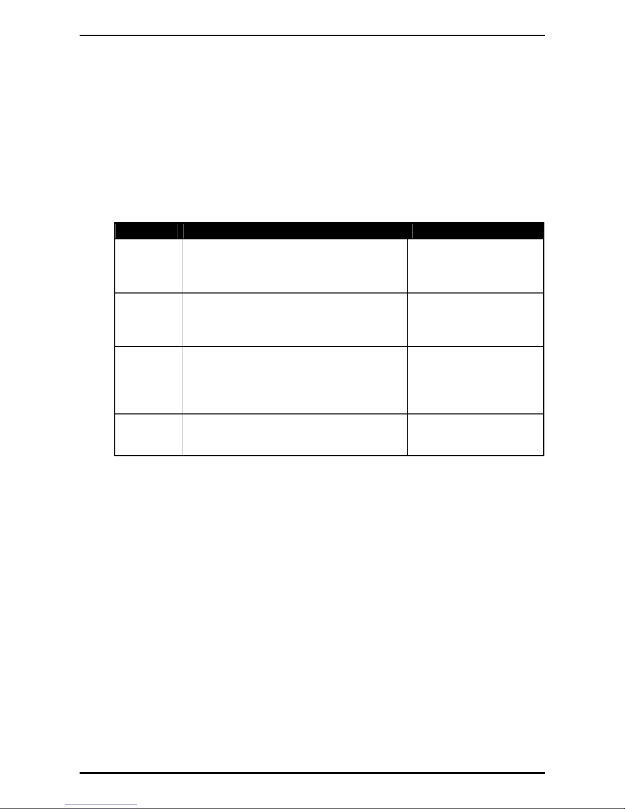
12.4. Error Messages
A number of error messages may be displayed to warn of operation outside of the
acceptable limits. These messages are described below. Short messages
(XXXXX) will appear as a single message on the display. Longer messages
(XXXXX) (YYYYY) will appear on the display in two parts, first the (XXXXX) part,
then the (YYYYY) part.
12.4.1. Weighing Errors
These messages show status messages or errors that may occur during normal
weighing operation.
Error Description Resolution
(U - - - - -) The weight is below the minimum
allowable weight reading.
(O - - - - -) The weight is above the maximum
allowable weight reading.
Warning - overloading may damage
mechanical scale elements.
(ZERO)
(ERROR)
The weight reading is beyond the limit set
for Zero operation. The operation of the
<ZERO>
installation. The indicator cannot be
Zeroed at this weight.
(STABLE)
(ERROR)
Scale motion has prevented a
<TARE>
or
command.
Reference Manual Rev 1.0
key is limited in the setup during
<ZERO>
operation from occurring on
Increase the weight or
decrease the minimum
allowable weight
reading.
Check the condition of
load cell connections.
Check for damaged load
cell.
Increase the Zero
Range (Z.RANGE) or
use the
<TARE>
key
instead.
Try the operation again
once the scale is stable.
003R-618-100 Page 49
Page 52
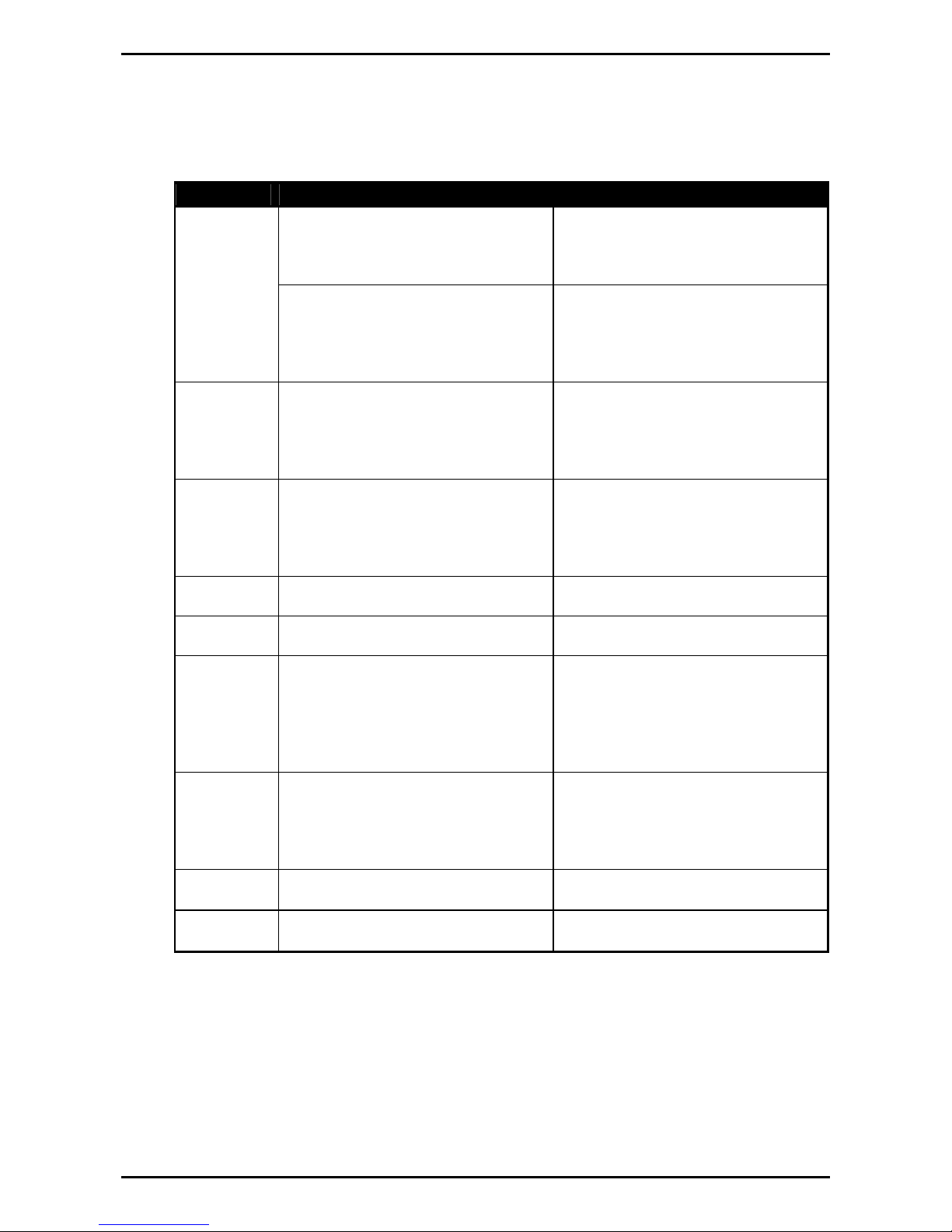
Reference Manual Rev 1.0
12.4.2. Setup and Calibration Errors
These messages show status messages or errors that may occur during the
instrument setup and calibration.
Error Description Resolution
The instrument may be in Safe
(DENIED)
Setup and an item that needs Full
Setup has been selected for
editing.
When accessing setup, more than
three attempts have been made
with the incorrect passcode.
Refer to Setup Lock-Out page 24
for more information.
(LIN.PT)
(LO)
An attempt has been made to
place a linearisation point below
zero.
(PT.TOO)
(CLOSE)
An attempt has been made to
place a calibration point too close
to an existing calibration point.
(RES)
(LO)
(RES)
(HIGH)
(SPAN)
(LO)
(SPAN)
(HI)
(ZERO)
(LO)
(ZERO)
(HI)
The scale build is configured for
less than 100 graduations.
The scale build is configured for
more than 30,000 graduations.
The load cell signal range (span)
is too small for these settings.
The load cell signal range (span)
is too large for these settings.
An attempt has been made to
calibrate zero below -2mV/V.
An attempt has been made to
calibrate zero above +2mV/V.
Access Full Setup to edit the item. (ENTRY)
Turn the instrument off. When the
instrument is turned back on,
enter the correct passcode to
access setup.
Incorrect linearisation point
entered (must be between zero
and full scale). Refer to Using
Linearisation page 38 for more
information.
Re-enter the calibration point.
Points must be spaced by at least
2% of full scale from each other.
Refer to Using Linearisation page
38 for more information.
Check the resolution (count-by)
and capacity settings.
Check the resolution (count-by)
and capacity settings.
Incorrect span weight entered
(must be between zero and full
scale). Scale wiring incorrect.
Wrong load cell capacity (too
large). Wrong or no calibration
weight added to scale.
Incorrect span weight entered
(must be between zero and full
scale). Scale wiring incorrect.
Load cell capacity too small for
application.
Scale wiring incorrect
Remove all weight from scale.
Scale wiring incorrect.
Page 50 003R-618-100
Page 53
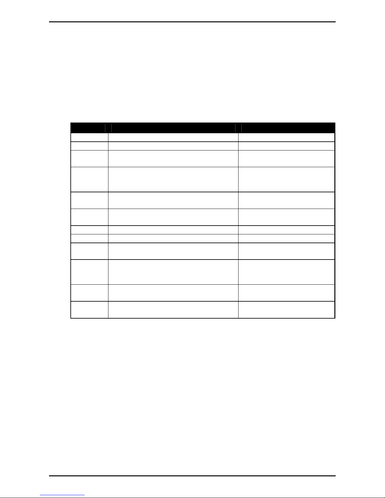
12.5. Diagnostic Errors
The instrument continually monitors the condition of the internal circuits. Any faults
or out-of-tolerance conditions are shown on the display as an E type error message.
In the table below the following terms are used:
• Check
: This item can be checked on site by service personnel.
• Return for Service
factory service.
Error Description Resolution
(E0001) The power supply voltage is too low. Check supply
(E0002) The power supply voltage is too high. Check scale / cables
(E0010) The temperature is outside of
allowable limits.
(E0020) Scale build is incorrect. The number of
graduations has been set too low or
too high.
(E0100) The digital setup information has been
lost.
(E0200) The calibration information has been
lost.
(E0300) All setup information has been lost Enter setup and calibrate
(E0400) The factory information has been lost. Return for Service
(E0800) The EEPROM memory storage chip
has failed
(E2000) ADC Out of Range Error. This may be
caused from a broken load cell cable.
(E4000) The battery backed RAM data has lost
data.
(E8000) The FLASH program memory is
incorrect
Reference Manual Rev 1.0
: The instrument must be returned to the manufacturer for
Check location
Fix up scale build
Re-enter setup
Re-calibrate
Return for Service
Check BUILD:CABLE
setting. Check load cell
cable, wiring, etc.
Re-enter setup
Return for Service
The E type error messages are additive. For example if instrument is running off
batteries and the temperature drops, the battery voltage may be too low. The
resulting error messages will be
hexadecimal as follows:
1 - 2 - 3 - 4 - 5 - 6 - 7 - 8 - 9 - A - B - C - D - E - F
003R-618-100 Page 51
E 0011
(0001 + 0010). The numbers add in
(For example, 2 + 4 = 6, or 4 + 8 = C)
Page 54
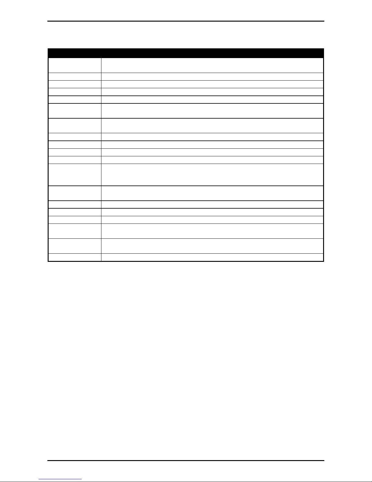
Reference Manual Rev 1.0
12.6. Glossary Terms
Term Definition
Count-by The smallest change in weight units that the display can show. See also
Resolution.
Division A single graduation.
EEPROM Electrically Erasable Programmable Read-Only Memory
EMC Electro-Magnetic Compatibility Regulation
FIR Finite Impulse Response
Full Scale The maximum gross weight allowed on the scale. This is used to detect
overload and underload conditions, etc.
Graduations The maximum number of display steps between zero gross load and full
capacity gross load. It is equal to the full scale divided by the resolution.
LED Light Emitting Diode
NTEP National Type Evaluation Program
OIML International Organization of Legal Metrolology
PLC Programmable Logic Controller
Range Total change in weight between zero gross load and full capacity gross load
(ie. the nominated total capacity of the scale). It is always given in displayed
weight units.
Resolution The smallest change in weight units that the display can show. See also
Count-by.
RFI Radio Frequency Interference
opto-LINK Cable opto-isolated infrared communications link cable
RS-232 Standard for communications hardware layers.
Step-Response The step-response is the time between placing a weight on the scale and the
correct weight reading being displayed.
Transients A temporary voltage oscillation or spike caused by a sudden change of load
(or other external influence).
Units The actual units of measurement (kilograms, tonnes, pounds, etc.).
12.7. List of Figures
Figure 1: Weight Indicator............................................................................................................... 3
Figure 2: Cable Connections ...........................................................................................................7
Figure 3: 4-Wire Connections ..........................................................................................................8
Figure 4: 6-Wire Connections ..........................................................................................................8
Figure 5: RS-232 - Instrument to PC using COM Port (DB9)...........................................................9
Figure 6: RS-232 – Instrument to PC using COM Port (DB25)........................................................ 9
Figure 7: RS-232 – Instrument to Printer (DB25)...........................................................................10
Figure 8: Remote Input ..................................................................................................................10
Figure 9: Instrument Outputs to Drive Relay..................................................................................11
Figure 10: Instrument Outputs to Drive PLC..................................................................................11
Figure 11: opto-LINK Attachment .................................................................................................. 12
Figure 12: Cable Shield Connection ..............................................................................................13
Figure 13: Editing Annunciators.....................................................................................................14
Figure 14: Display and Controls Illustration ...................................................................................16
Figure 15: Chart - Zero and Span Points to Interpolate Weight from Load Cell ............................36
Figure 16: Chart - Non-Linear Characteristic for Load Cell Output................................................38
12.8. List of Tables
Table 1: Status Annunciators.........................................................................................................17
Table 2: Industrial vs OIML and NTEP Modes...............................................................................22
Page 52 003R-618-100
Page 55

4
4-Wire Connection, 8
6
6-Wire Connection, 8
A
ADDRES, 33
AUT.OFF, 31
Automatic Weight
Output, 40
Auxiliary Connection, 9,
40, 42
B
B.LIGHT, 31, 48
Basic Operation, 16
Basic Weighing
Terminology, 21
BAUD, 32, 48
BITS, 33, 48
BUILD, 27
C
CABLE, 7, 8, 28, 48
Cable Connections, 7
CAL, 29
Calibration, 36
Calibration Counter, 23
CAP, 27, 48
Clear Linearisation, 39
CLOCK, 34
CLR.LIN, 29, 39, 48
Communications
Manual, 4
Connecting Shields, 13
COUNT, 43
D
Data Entry, 14
Numeric Entry, 15
Selections and
Options, 15
DAY, 34
DC Power Supply, 7
DEFLT, 35
Diagnostic Errors, 51
Digital Calibration with
Test Weights, 36
DIR.SPN, 30, 48
DIR.ZER, 29, 48
Direct mV/V
Calibration, 37
Direct Span Calibration,
38
Direct Zero Calibration,
37
Document
Conventions, 4
DP, 27, 48
E
Earthing, 13
ED.LIN, 29, 39, 48
Edit Linearisation
Points, 39
Reference Manual Rev 1.0
13. Index
Editing Annunciators,
14, 17
Electrical Safety, 6
EMC Immunity, 6
End – Leaving Setup,
35
Error Messages, 49
Exiting Digital Setup,
35, 48
Exiting Full or Safe
Setup, 26
External Output Drivers
- Connection, 42
F
FAC.CAL, 30, 35, 48
FACTRY, 35
FILTER, 28
FILTER (Reading
Average)
Filtering Techniques,
22
FORMAT (Date), 34, 48
FRC.OUT, 35, 48
Front Panel, 16
Special Function
Key, 43
Full Digital Setup
Passcode, 30
Full Setup Passcode,
24
FULL.PC, 30
FUNCTION Key, 20, 43
Function Keys, 17
Editing Function, 17
Primary Function, 17
G
General Setup
Information, 21
Glossary of Terms, 52
GROSS/NET Key, 19
opto-LINK Activation,
19
Group and Items, 26
Groups and Items, 27
H
HI.RES, 27, 48
HOLD, 44
HOUR, 34
I
Industrial vs OIML and
NTEP Mode, 22
INIT.Z, 28, 48
K
Key Functions, 43
KEY.FN, 31, 43, 48
KEY.LOC, 31
Keypad
Normal Operation,
14
, 48
L
L.in P, 29, 39
LIVE.WT, 44
Load Cell Connection,
7
Load Cell Signals, 7
M
Master Serial Output,
41
MINUTE, 34
MONTH, 34
MOTION, 18, 28, 48
N
NONE, 43
NVRAM, 3
O
Operator Manual, 4
OPTION, 28
OPTION (Scale
Options), 18
opto-LINK, 12
Outputs, 11
P
Passcode, 21
PEAK HOLD, 44
POWER Key, 18
Automatic Operation,
18
PRINT Key, 20
Printing, 41
Counting
Information, 41
Counting Sample, 41
Format, 41
Gross or Net, 41
Q
Quick Start Manual, 4
R
Reference Manual, 4
REM.FN, 32
Remote Function, 10,
32
Remote Input, 10
RES, 27, 29, 48
Restore Factory
Settings, 35
, 52
RFI
RS-232 Serial, 9
RST.CON, 33
S
S.in P, 29, 37
Safe Setup Passcode,
24
SAFE.PC, 30
SCALE, 7, 48
SCALE (Scale Base
Test Display), 34
Scale Build, 7, 29
Sealing Details, 47
Sealing Requirements,
13
SERIAL, 32, 40
Serial Communications,
40
Serial Output, 40
Serial PC Link, 9
Serial Printer
Connections, 10
Serial Remote Display,
10
SET.PTS, 33
Setpoint Operation, 42
Setpoints, 42
Setup Display Prompts,
26
Setup Errors, 50
Setup Menu Quick
Reference, 48
SHOW.T, 45
Sigma-Delta A/D
converter, 3
SPAN, 29, 48
Span Calibration
Routine, 37
SPEC, 30
Special Functions, 43
Specifications, 4, 5
SRC, 33
Stability
Considerations, 18
T
TARE Key, 19
TARG.HI, 33, 42
TARG.LO, 34, 42
TEST, 43
TEST (Special Test
Functions), 34
TYPE (Serial Output),
32
U
UNITS, 27, 43, 48
Units Display, 16
USE, 22, 23, 28, 48
Using Linearisation, 38,
50
W
Weighing Errors, 49
Weight Display, 16
Y
YEAR, 34
Z
Z.BAND, 29, 48
Z.in P, 29, 37
Z.RANGE, 18, 29, 48
Z.TRAC, 28, 48
ZERO, 29, 48
Zero Calibration
Routine, 37
ZERO Key, 18
003R-618-100 Page 53
Page 56

Notes:
Reference Manual Rev 1.0
Page 54 003R-618-100
Page 57

Notes:
Page 58

 Loading...